Many thanks to SWLing Post contributor, Don Moore–author of Following Ghosts in Northern Peru–for the following guest post:
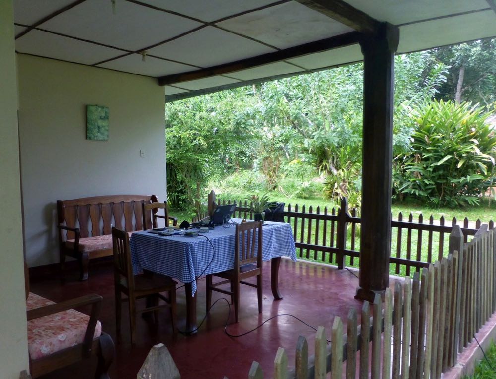
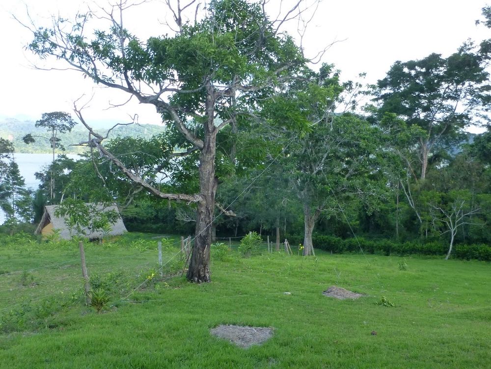
One of my favorite DXing locations was this little cottage at the El Rancho Hotel just outside San Ramon, on the edge of the Amazon jungle in Peru. At $18/night, including breakfast, the hotel was a bargain, and there was plenty of room for my delta loop.
A Guide To Vagabond DXing
By Don Moore
Ever since I served as a Peace Corps volunteer in Honduras in the early 1980s, Latin America has been my primary focus for both DXing and traveling. So when I retired in 2017, my main goal was to begin taking long annual trips . . . and I do mean long. From October 2017 to May 2018, I traveled through Peru, Ecuador, and Colombia visiting about fifty different towns and cities. This year, I’m on a five-month trip through southern South America. In Latin America you can get just about anywhere cheaply and easily by bus, so that’s how I get around. It’s also a great way to meet people and to see the countryside. But luggage can become a burden, so I limit myself to a single mid-sized wheeled suitcase and a large knapsack. And that means that my mobile DX shack has to be very carefully planned.
Your plans may not include multi-month odysseys like mine, but I think my experiences will help you prepare to DX on your next trip, wherever it might be. Of course, what makes a good mobile DX shack depends on what your DX interests are. I consider myself a station collector, in that I want to make loggings of lots of new and different stations and to build up an understanding of radio broadcasting in different regions. So on my travels I concentrate on the medium wave broadcast band and longwave beacons, with maybe little bit of shortwave utility DX. (There’s not much on shortwave broadcast that I can’t also hear at home.)
Take the DX Home With You
For years my standard DX travel gear was a Sony ICF-2010, a cassette recorder, and an old Radio West ferrite loop antenna. But listening time was always limited since it was a vacation. There were other activities on the agenda and I was generally too tired to get up early for DXing. I always went home with some interesting loggings and audio recordings, but once I left for home the DXing was done.
SDRs have changed all that and now my first rule of travel DX now is take the DX home. The best souvenir of a trip is the hundreds of hours of DXing that I take home with me. In a 2016 trip to central Colombia, I made about 300 MB of recordings of the medium wave band. While listening to them later I logged over 400 stations from twenty countries (and I still have about half the files to go through). I never would have even gotten close to that many stations listening on my Sony like an ‘old-fashioned’ DXer, hi!
Lately, I’ve been accumulating SDR files much faster than I could possibly go through them, so it’s a fair question to ask what the point is. When will I ever listen to them all? Like most DXers, I’m not fortunate enough to live in a perfect DX location. When conditions are mediocre, I’d rather spend my DXing time going through some more interesting SDR files. And, I know I’ll have lots of good DX waiting for me years from now when I’m no longer able to travel the way that I do now. For me, SDR recordings make much better souvenirs that some cheap tourist trinkets that will gather dust on a shelf. It doesn’t matter whether your travels take you to a nearby park or to a distant continent. SDRs can preserve the DXing experience for years to come.
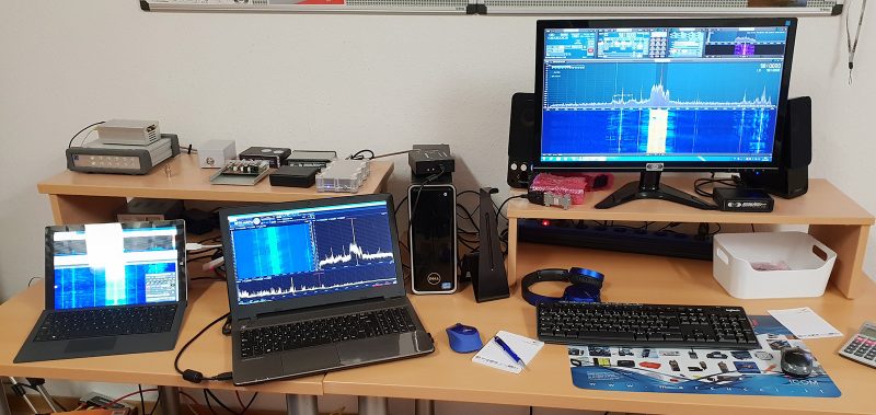
My Mobile DX Shack
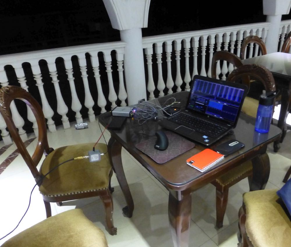
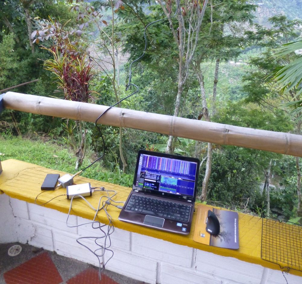
This is my typical DXing setup with the Afedri. The rooftoop terrace at the Hotel Rosa Ermila ($10/night) in Cascas, Peru was the most elegant place I’ve ever DXed from, but reception was only average with the PA0RDT dangling from the railing.
The centerpiece of any DX shack is the receiver. On my 2017-18 trip, I had an Afredri SDR-Net with an SDRPlay RSP1 as a backup, but this year I replaced the Afedri with an Elad FDM-2. Together, my two SDRs are smaller than all but the smallest portable receivers. Of course I also need a laptop, but I’m going to take one anyway. An important consideration in selecting a travel SDR is to get something that is powered off the laptop’s USB connection so that it is easy to DX totally off battery power if line noise becomes an issue.
The other vital component of DXing is the antenna. A good on-the-road antenna for SDR DXing has to be small, easy to erect, broadband, and versatile. That sounds like a lot to ask, but the perfect DX travel antennas do exist.
For compactness and ease of use, nothing can surpass the PA0RDT mini-whip. How good is it? That’s what I used to log over 400 medium wave stations in Colombia in 2016. I just attached the unit to my coax and threw it about three meters up into a short tree. The antenna works best when mounted away from nearby structures, but sometimes I’ve gotten decent results placing the PA0RDT on balconies and windowsills of tall buildings. It’s mostly a matter of luck as to how bad the local noise levels in the building are and how much the building itself may block signals. Using a short support, such as a broom or a hiking pole, it may be possible to mount the unit a meter or so away from the building.
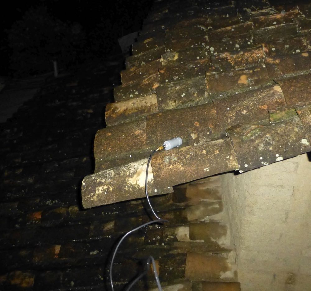
While it’s best to mount the PA0RDT away from obstructions, the antenna might give good results anywhere, even on the neighbor’s roof. (Just make sure it’s not likely to get stuck. Pulling the unit out of a stubborn papaya tree is no joke.)
The biggest drawback of the PA0RDT for serious MW and LW DXing is that it is non-directional. For a directional antenna, a Wellbrook loop is great if you’re traveling by car, but that one-meter diameter aluminum loop doesn’t fit in my suitcase. Fortunately, a few years ago Guy Atkins and Brett Saylor told me about an alternative: buy a Wellbrook ALA-100LN unit and attach it to a large homemade wire loop. Now my travel kit includes two nine-meter lengths and one eighteen-meter length of #18 stranded copper wire. The wires can be spliced together for loops of 9, 18, 27, or 36 meters circumference, according to what fits in a location. Erection of a wire loop is easy enough with a suitable tree branch. I just throw the wire over the branch and then form it into delta (with the bottom running just above the ground) using two tent stakes and some short cord to hold the corners. The ALA-100LN unit goes in the bottom center.
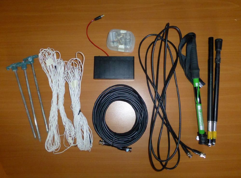
Items that go in my suitcase, left to right: tent stakes and wire for the Wellbrook loop, a small box with more adapters, another battery box, 50 foot coax, 12 foot coax, and my hiking pole. The pole doubles as a support for the PA0RDT sometimes.
The loop doesn’t have to be in a delta; that’s just often the easiest to erect. I’ve successfully used squares, rectangles, trapezoids, oblong diamonds, and right angle triangles. Any balanced shape with the ALA-100LN in the bottom center should be bi-directional in a figure-eight pattern. Non-balanced shapes will work equally well but with unpredictable directionality. Just keep the wire in a single plane and place the ALA-100LN unit someplace along the bottom.
Both the PA0RDT and the Wellbrook require a 12V power supply. The North American version of the Wellbrook comes with an excellent noise-free 110V power supply, but that’s of no use in 220V countries and also I want to be able to DX totally off battery power when necessary. Fortunately both antennas use the same size power connector, so I carry three eight-cell AA battery packs for remote power.
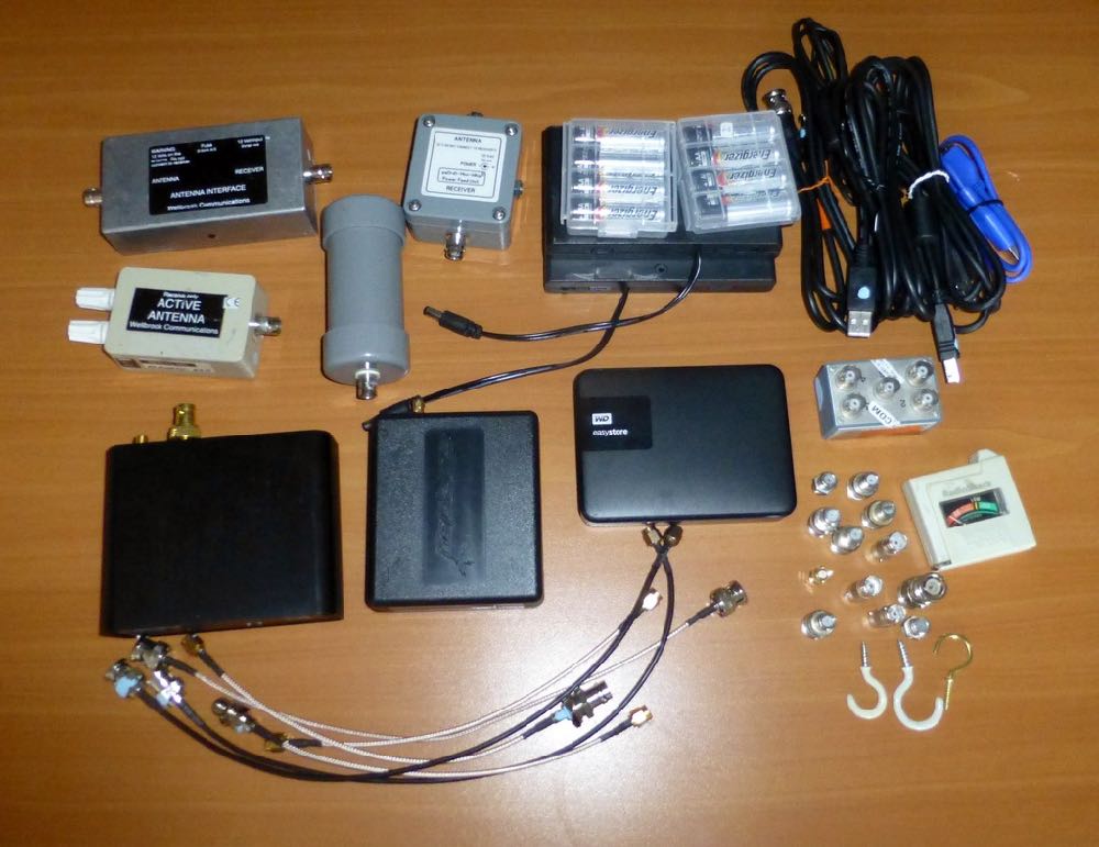
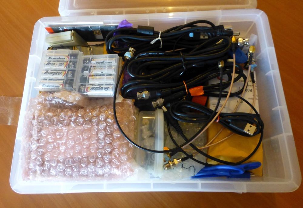
Contents of the DX box, clockwise from upper left: the two pieces of the Wellbrook ALA-100LN, the two pieces of the PA0RDT mini-whip, two 8xAA battery boxes and a set of batteries, USB and coax cables, a passive 4-way antenna splitter, battery tester, various adapters and cup hooks (for securing wires), 4TB hard drive, the SDRPlay RSP1, the Elad FDM-2, and more short patch cords.
My mobile DX shack is rounded out with everything that is needed to connect the parts together. I have at least four of every adapter and patchcord, since I know they won’t be easy to replace on the road. For lead-ins, I have 12-foot and 50-foot lengths of lightweight coax with BNC connectors. I also have a few F-to-BNC adapters so I could buy some standard TV coax if needed. A 4 TB hard drive provides plenty of space the SDR recordings I plan to make. (Before leaving, I fill it with videos that I can delete after I watch them or when I need space.) For DX references, I download various station lists online so that I have them available even if I don’t have an Internet connection. It’s also important to keep those lists with the SDR files from the trip so that if I’m listening to the files years from now I’ll have references which were current at the time.
Airport Security
A common concern for traveling DXers is getting through airport security. When I went to Colombia in 2016, I wrapped my DX gear in clothing for protection and then stuffed everything into my backpack. Security didn’t like what they saw and I had to empty the bag so that every single item could be examined and swabbed for explosive residue. The TSA lady was very nice about it, but I wanted to minimize the chance of that happening again.
At an office supply store I found a plastic storage box that fits inside the main pocket of my backpack. My SDRs, antenna components, and hard drive get wrapped in bubble wrap and all placed together in the box along with small cables, adapters, etc. Larger items – the wire, coax, and stakes for the loop – get packed in my checked bag.
The DX Box packed and ready to go.
At the airport, I slide the box out of my backpack, place it into a cloth shopping bag, and then send it through the X-Ray machine on its own so that the agent can get a close look at the contents. So far in about a dozen security checks in the USA, Peru, and Mexico, the box of gear hasn’t caused so much as a pause on the conveyor belt. And, if the box would get pulled for a closer look, at least I won’t have to empty the entire backpack again.
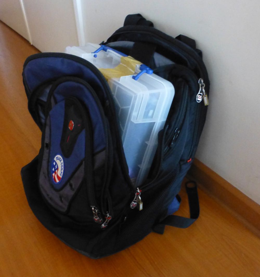
Most of my equipment fits in this plastic box which slides into my backpack.
Where to DX
A mobile DX shack isn’t worth anything without a suitable place to DX from. Hotels may work if you have a balcony where you can put a small antenna, but more likely than not there’ll be problems with RF noise. The best hotels are ones that are a collection of cottages or bungalows or that otherwise have an open yard-like space for an antenna. My favorite place to find possible DXing sites is on AirBnB. It’s often easy to find AirBnBs that are on the edge of town or even in the countryside with lots of space. Of course, since I don’t have a car, I need to make sure I can get there using public transportation.

While visiting Huanchaco, Peru with DX friends Karl Forth and John Fisher, we had a beach-front apartment with an adjoining rooftop terrace. We had excellent results with an oblong loop and the ALA-100LN on the terrace.
The key to selecting a DX location is to examine all the photos very carefully. Is there open space for the antennas? Are there trees or other potential supports? Is there a gazebo, terrace, or other space that could be used for DXing? Google satellite view and Google street view can be very helpful in scouting out a location (And it’s surprising how much of South America is now on Google Street View.) And, I always look for possible noise sources. One place I almost rented in Colombia turned out to have high voltage power lines running next door when I found it on Street View.
I always tell the hotel staff or AirBnB host what I’m doing so that they understand why the gringo has wires running around. And I make sure not to put my antennas or coax anywhere that might interfere with the employees or other guests. Most of the time I’m able to erect the antenna near my room and run the lead-in into my room through a window. Then I can leave my laptop running all night to make scheduled SDR recordings. That’s the Holy Grail of DXing – catching the overnight DX while you sleep. But if my room turns out to have too much RF noise (as has been the case a few times), then I head out to the gazebo or terrace to DX using battery power. That does mean I have to stay up late or get up early since I can’t leave the laptop outside on its own. But, some of the best DX that I’ve had has come from running off full battery power in gazebos.
My delta loop had plenty of space at the Posada de Sauce ($25/night with breakfast) in the jungle near Tarapoto, Peru. The lodge was totally powered by solar panels and was one of the quietest places I’ve ever DXed from.
Antenna security is another consideration. At one place I stayed I wasn’t comfortable leaving my expensive antenna components unattended outside all night. And then there was what happened on my first trip to Colombia in 2010. I knew that a place I would be staying at for two nights had an open field right behind it, so on that trip I took 500 feet of thin insulated wire for a mini beverage-on-the-ground. DXing was great the first night but terrible the second. When I went out the next morning to wind up the wire I learned why. The worker who had been weed-wacking the hotel gardens the previous day had also done the field, and in doing so he had cut my wire in three places. He had, however, very nicely tied the wires back together.
Share the DX
DXing off battery power in the gazebo in the Mauro Hilton Hostel in the mountains above Manizales, Colombia. The antenna was the PA0RDT thrown in a tree. I had great DX with the loop from my room, but I came here to enjoy the views one evening.
Finally, if you take an SDR on a trip and get some good DX, make a selection of your files available for download. Other DXers will enjoy hearing what the band sounds like somewhere else. Several dozen of my files from Peru, Ecuador, and Colombia are available for download in a shared Google Drive folder. If you see something you want, be sure to download it now. The winter DX season is just starting here in deep South America and in the coming weeks I’ll be replacing some of those older files with ones made in Argentina and maybe in Uruguay and southern Brazil. I’ve found a lot of places to stay that look to be perfect for a vagabond DXer.
Links
- My Shared Google Drive Folder where you can find some samples of my on-the-road SDR recordings
- The Wellbrook ALA 100LN unit
- The PA0RDT miniwhip – see the email address at the bottom of the article for ordering information. I highly recommend getting the original PA0RDT. There are several cheaper versions for sale, but DXers have reported quaility control problems with those.
- The storage box that I found at an office supply store.
- My 2016 Colombia DX Log
- My Homepage
For fun, here are some of the better places I DXed from in Peru, Ecuador, and Colombia. The key thing to look for is an open place for the antennas:
- Mauro Hilton in Manizales, Colombia (No connection to that other Hilton)
- AirBnB in Loja, Ecuador
- AirBnb in Huanchaco, Peru
- Mitu Wasi Hospedaje in Tarapoto, Peru
- Posada de Sauce in Sauce, Peru
- Bungalows El Rancho, San Ramon, Peru
- The Rosa Ermila Hotel in Cascas, Peru. The DXing wasn’t very good, but I had the rooftop terrace all to myself.

Don, thank you so much for sharing your travel DXing expertise. This article is absolutely brilliant and so informative for anyone who wishes to make SDR field recordings. I love how carefully you’ve curated and distilled your portable setup and have given priority to having antennas for all occasions. I also think carrying spare parts and, especially, a spare SDR makes a lot of sense.
Post Readers: As we mentioned in a previous post, Don is an author and has recently published “Following Ghosts in Northern Peru: In the Footsteps of 19th Century Travelers on the old Moyobamba Route” which is available in Kindle and print formats via Amazon.
Purchasing through this Amazon link supports both the author and the SWLing Post.
Click here to check out other guest posts by Don Moore.
Do you enjoy the SWLing Post?
Please consider supporting us via Patreon or our Coffee Fund!
Your support makes articles like this one possible. Thank you!