Category Archives: Antennas

Guest Post: Tom’s Backpack Shack 3.0

Many thanks to SWLing Post contributor, TomL, who shares the following guest post:


Backpack Shack 3 – Amplified Whip Antenna

by TomL

So, having enjoyed using the Ferrite Sleeve Loop I created last year, I have wanted something a little more sensitive and less bulky.  I will eventually create a much BIGGER FSL antenna on the order of 2 feet long and perhaps 18 or 24 inches in diameter for indoor/attic use.  But that is not a priority at the moment.

Since I already have the DX Engineering Pre-Amplifier and the very nice Cross Country Preselector from the loop project, I thought it might be useful to create an active whip antenna for it.  And the cool looking Solar Red backpack needed something to do!

Power

Now that the bulky loop was not taking up the main compartment of the backpack, I could think about what else to put in there, like a larger power pack.  I scoured FleaBay for ideas and stumbled upon this contraption for backup power to network systems, the CyberPower CyberShield for Verizon.

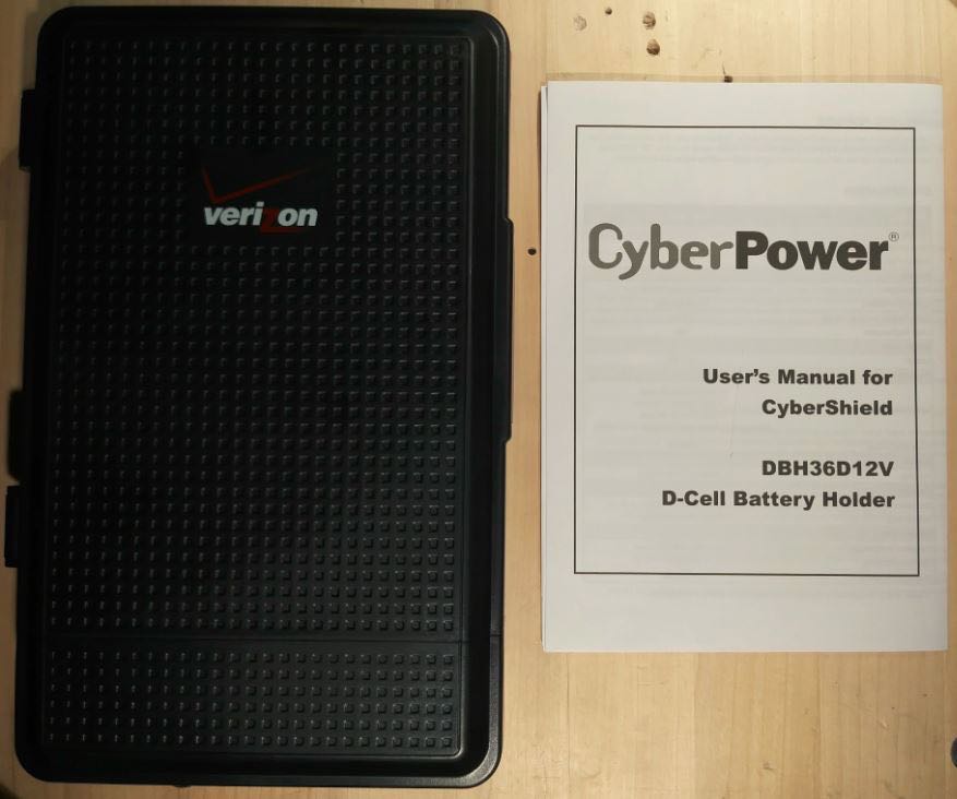
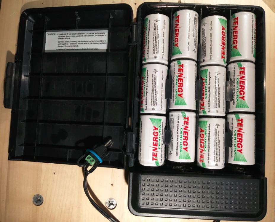
This has 12 spaces for D-cell batteries and was mounted inside the demarcation terminal to provide backup power for things like cable systems and Copper-to-Ethernet networks.  It is not waterproof, so would be inside the premises of the customer getting the internet/cable service. But my Pre-Amp needs 12-18Volts and would love to have nearly unlimited power.  So, I bought a used one, cut the end off of the power lead and put on my own 2.1×5.5mm plug (carefully glued down and tie-wrapped). Then I filled it with 1.2Volt Tenergy D-cells.

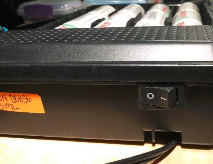
Everything was just fine until I forgot to double check the polarity of the plug that I had wired onto the end.  Plugged it into the DX Engineering Pre-Amp, flipped the power switch and fitzzz…. The Pre-Amp light went on, then off (permanently!).

So, my expensive mistake is that I start using the FREE multimeter I got from Harbor Freight and check the polarity before I connect homemade battery packs to anything!!

DX Engineering charged me $60 to fix my mistake and it is working fine now after I swapped the wires on the plug. Yes, their Pre-Amp is NOT reverse-polarity protected! Disappointing, since the price tag for that device is $148!!!  The CyberShield now sits comfortably inside the bottom of the backpack.
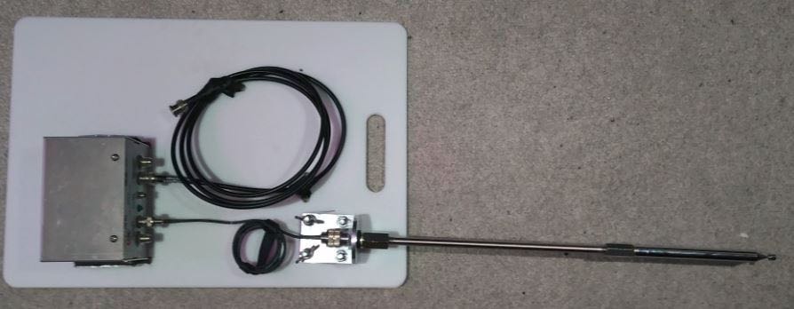
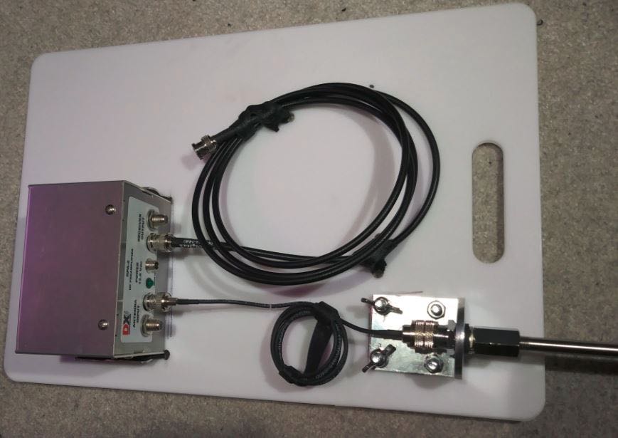
Antenna

Now that the drama was over regarding the Power pack, I could think about the whip.  I did not want a wimpy whip! (No one should rightly aspire to this, in my opinion). More FleaBay searches found me looking at Trucker parts.  Loaded whips, magnetic mounts, 10 foot tall MFJ telescoping whips, etc was looking a bit expensive.

Besides that, I cannot fit a 10 foot tall telescoping whip into the backpack, I am limited to at most 18 inches (and that is at an angle to fit it in there).  But I found an old-fashioned mirror mount that looked promising since it had a nice SO-239 connector at the bottom and standard CB antenna fitting on top of 3/8”-24.

Then I found the 44 inch SuperAntenna with the same threads; then found the replacement Stainless Steel Shafts for a Wilson antenna in different lengths (I ordered the 10 inch version to test).  With a couple of rod coupling nuts and I was ready for testing!
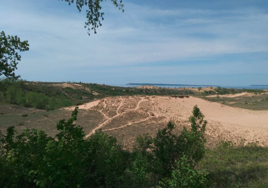
Test Locations

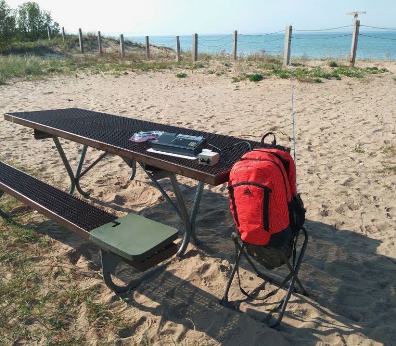
I had already scheduled a short vacation to Sleeping Bear Dunes on the thumb of Northwestern Michigan, so I took this test setup with my Sony ICF-2010. This area is a very nice remote National Lakeshore with minimal noise.  I tried a beach setting and a couple of hilltop picnic areas (including meeting a local Porcupine) and had very nice reception at all locations. The hilltop locations are approximately 400 – 600 feet above the Lake (yes, the Dunes are THAT big there!).

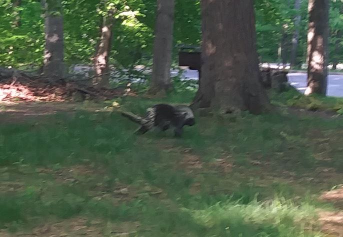
Meeting a local Porcupine

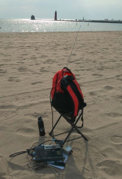
Later on, I went to Grand Haven, MI on the way home and stopped at their very lovely beach.

Reception was just as good as the hilltop locations at Sleeping Bear! In both areas, I was next to a large body of water (in this case, Lake Michigan) and makes for an advantageous place for DXing!  I had also stopped at a Rest Area off the highway and that was a terrible place even though it was electrically quiet but nowhere near the big Lake. I guess the rumors are true about being near a large body of water somehow enhances reception of weak signals–?

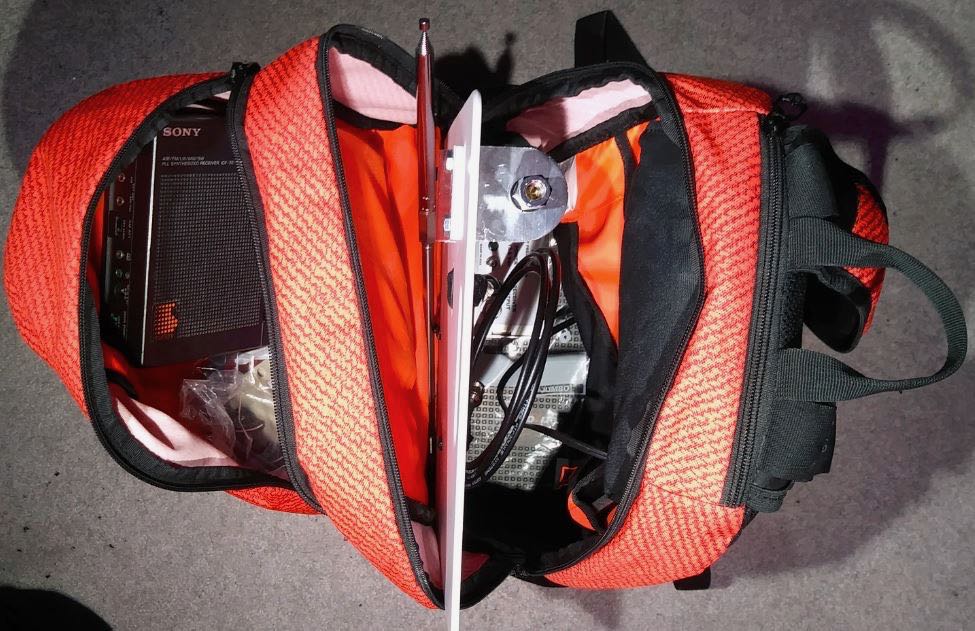
I will submit recordings later since I lost the mini-B cable for the Sony digital recorder and had to order a replacement.  However, this was a nice project that freed up some space inside the backpack. I will add an 18 inch extension to the whip that will give me a total length of 72 inches.  Plus, it is mounted 12 inches up on the poly cutting board and I place the backpack on a small hunters folding chair that is about 24 inches tall. So, the tip will be about 9 feet off the ground.

Not pictured but I was also able to easily fit inside a used CCrane Twin Coil Ferrite antenna for mediumwave use that also performed very well.  I noticed that the picnic benches at some locations are made of metal, so that gives me a future idea of trying to leverage that to use as a ground plane somehow.  The battery pack is heavy but also gives great ballast to the backpack and will not tip over. Cannot wait for the Tecsun S-8800 to arrive so I can try leaving the radio inside the bag and just use the remote control to tune!

Happy Listening,

TomL

Parts List


As always, I’m so impressed with your spirit of radio adventure, Tom! I love the fact that your goal is to make a field-deployable DX kit that isn’t cumbersome or time-consuming to set up on site. I imagine you only need a couple of minutes to open the pack and have it on the air. 

Those DXing spots are stunning! I had no idea one could find 400-600′ dunes in NW Michigan–! With that said, I’ve heard that part of the state is one of exceptional natural beauty.  If you could somehow turn the lake into a body of salt water–thus increasing ground conductivity–you’d really enhance that already impressive reception! I’m guessing that sort of project would be a bit outside your budget! Ha ha!  That and the freshwater fish might protest!

To me, there is no better way to enjoy radio than finding a nice RF quiet spot in the great outdoors…no matter where you live in the world. On top of that, Tom, you’re constantly building, experimenting, documenting and sharing your findings–you’re a true radio zealot! Huzzah!

Post readers: Read Tom’s past contributions and articles by clicking here

Click here to read Backpack Shack 3 – Part 2.

Ham Radio Friedrichshafen 2018 Vendor Photos

Many thanks to SWLing Post contributor, Mehdi Asgari (DF2HF / NM9A), who shares photos from the Friedrichshafen ham radio convention this year. Tomorrow, we’ll post his photos of the flea market area!


Ham Radio Friedrichshafen 2018

by Mehdi Asgari (DF2HF)

Mehdi is a software engineer and SDR lover working in Berlin. He’s a licensed ham (DF2HF & NM9A) and also a member of EP2C club.

Test the MegaDipole MD300DX wideband active dipole via a KiwiSDR

In reply to our post about the Bonito MegaDipole MD300DX wideband active dipole antenna, SWLing Post contributor, Mark, comments:

Dennis from Bonito kindly sent me a sample megadipol and I’m truly impressed with it. The SNR is amazing right through the shortwave spectrum and really helps pull out weak signals.

I was particularly impressed to be able to pick up World Music radio on 5840 kHz all the way here in Ireland with just 100 watts in the evenings.

It’s also quite excellent on LW/MW.

See for yourself on my KiwiSRR just check out the SNR !!!

Click here to load Mark’s KiwiSDR in a new web page.

Thanks, Mark, for hooking the MegaDipole up to your live KiwiSDR!

Gary pulls apart and examines the XHDATA D-808


Many thanks to SWLing Post contributor, Gary DeBock, who shares the following report of the XHDATA D-808:


XHDATA D-808 AM-LW-FM-SW-AIR Portable- Tech Report

by Gary DeBock

The XHDATA D-808 portable is an AM-LW-FM-SW-SSB-AIR band model which has already been the subject of many excellent reviews. Until recently the model was not marketed to North American purchasers, but recently a couple of Chinese sellers have started soliciting North American buyers via eBay listings.

My own interest in the model was in comparing its AM Band performance to that of the best performing Ultralight radios– specifically the CC Skywave and Skywave SSB models. Although the D-808 is slightly larger than the 20 cubic inch limit for Ultralight radios, its size and weight make it very convenient to take along as a “travel portable,” specifically as an SSB-enhanced model capable of checking transoceanic station carrier strength on exotic ocean beaches. The Skywave SSB model can also do that– but at a $169.99 list price, compared to the $112.86 (plus $10 shipping) cost of the D-808. In addition, none of the published D-808 reviews seemed to have any information about internal components like the loopstick, or Si4735 DSP chip.

My first test was to compare the stock Skywave SSB model with the D-808 in fringe AM station reception. The Skywave SSB model has a reputation of being one of the most sensitive Ultralight radios, but the D-808 clearly outperformed it on both low band fringe station (550-KARI) and high band fringe station (1700-City of Auburn TIS) reception. The D-808 couldn’t quite hang with a 7.5″ loopstick Skywave model, but that only made me curious about how the same modification could enhance the D-808. So… it was time to disassemble the D-808, and find out why its loopstick was such a superior performer.

The D-808’s 3 7/8″ (98mm) loopstick is shown adjacent to the 2 3/4″ (70mm) loopstick of the CC Skywave models. The D-808 is much easier to disassemble than the CC Skywave models, though, so enhanced loopstick transplants should prove to be quite popular in the D-808.

The D-808 loopstick is 3.7/8″ (98mm) long, while that of the CC Skywave SSB model is only 2 3/4″ (70mm) long. Other reviewers have noted the excellent performance of the D-808 on the AM band, and this is probably one of the main reasons. The SSB mode operates very similar to that of the Skywave SSB in providing a quick check of carrier strength on weak AM band targets– the LSB mode can be set to +55, and the radio tuned to different frequencies to check fringe station carrier strength. This can provide a real-time check of propagation changes during time-limited propagation openings for live ocean beach DXing with Ultralight radios or other portables (or with the D-808 itself, if desired).

The D-808’s Si4735 DSP chip was initially used in the Eton Traveler III Ultralight radio model, which was fully reviewed in the 2015 Ultralight Radio Shootout (where it won top honors for MW sensitivity). The D-808 augments that capability with a significantly longer loopstick, plus multiple DSP filtering selections. As such, the D-808 in stock form should be a very superb performer.

The Si4735 DSP chip has markings of “3560, DCUL, .738” and provides a wide range of AM bandwidth choices for the Medium Wave DXer (6K, 4K, 3K, 2.5K, 2K, 1.8K and 1K). These perform very well, and as with the other DSP-enhanced portables, the narrowest bandwidth (1K) provides the most sensitive AM band reception.

In construction very similar to that of the CC Skywave, the D-808 separates into two main circuit boards, connected together by a plug-in ribbon cable. One strange quirk is that the Si4735 DSP chip is located on the RF board (close to the center right edge). The Si4735 DSP chip is also used in the Eton Traveler III Ultralight radio, and although that model lacks the multiple DSP filter selections of the D-808, is has been the subject of highly successful 7.5″ loopstick transplant modifications– proving that such enhanced Medium Wave and Longwave loopsticks will perform very well in the new, Si4735 chip- powered D-808.

Disassembly of the D-808 model is fairly straightforward in comparison to the CC Skywave models, and the technician doesn’t need to memorize a detailed reassembly protocol in order to perform a routine loopstick transplant operation. Neither C.Crane nor XHDATA are likely to show any sympathy to someone botching up an antenna transplant, so you need to be confident that that your skills are superior to those of the company technicians before taking the plunge. In the CC Skywave and CC Skywave SSB models various parts fit together like a puzzle, but the D-808 isn’t like that. It should prove to be a fairly popular model for enhanced MW and LW loopsticks.

Those considering a purchase of the D-808 should be advised that its type 18650 Li-ion 3.7v battery is not commonly available at most stores, and that Postal regulations supposedly forbid shipping these batteries through the mail. One of the eBay sellers (harelan ecommerce) did manage to ship me two of the standard XHDATA type 18650 batteries through the mail (along with two new D-808 models) but if your seller won’t do this, you can still purchase the batteries on eBay. Some of the 18650 batteries sold on eBay have a flat positive terminal which won’t contact the D-808 cabinet’s positive battery connector terminal, but in such a case you can simply insert a #8 lockwasher in between the two, and the arrangement will be very secure. From that point on you can simply recharge the battery with a USB terminal connector.


Thank you for sharing this technical overview of the XHDATA D-808, Gary! I’m looking forward to the antenna mods you’ll no doubt make to this compact DX machine!

Click here to read other posts about the XHDATA D-808 and here to read posts by Gary DeBock.

How to build SM0VPO’s 20 meter magnetic loop antenna

The completed 20 meter loop antenna.

A few days ago, SWLing Post contributor, Robert Gulley (AK3Q), pointed me to an excellent website by Harry Lythall (SM0VPO) which is chock-full of various homebrew radio projects. In particular, we both were impressed with Harry’s 20 Meter Loop Antenna–it’s such a simple project and requires no special order components. In fact, all of the components (save, perhaps, the antenna connector) can be purchased at a DIY store.

I reached out to Harry and he has kindly allowed me to republish this project as a guest post:


20m Loop Antenna

by Harry Lythall – SM0VPO

Introduction

I recently saw that my 80m (3.5MHz) loop (or frame) antenna has been really popular, and that there are loads of other radio amateurs who have taken my design and “ran with it” to produce variations that all have some great improvement. There have been many in-depth tests and simulations, all with exceedingly good results and reports. This is exactly what I am aiming for with my homepages – free information for all and my designs being improved upon. That way we all win 🙂

One small point all variations have in common is the need for an expensive tuning capacitor and a very restricted RF power level. Of course, you can throw money at the problem, but for me this hurts. I got to thinking that there must be a way of adjusting the design a little and finding another technique to tune the antenna, and to make the best use of the little radio transceiver I have in Sweden, given the limited space.

My limited space apartment.

As you can see there is not much opportunity for grand antennas. And to add to this, the equipment I have in Sweden is also limited to a single 5-Watt unit.

My limited equipment – only 5-Watts.

The Design Thoughts

Today I have no area of land to use for antennas. I have a glassed-in balcony on the 4th floor of an apartment block. I really like the 20m (14MHz) band so I will concentrate on that. I am not really interested in the CW end of the band, except perhaps 14.070MHz for the digimodes. So my requirements are:

  • As efficient as possible (useable)
  • Small size, also portable so I can use it for field use
  • No expensive components, everything available locally
  • No TVI, QRM or interference to stereos or computer sound
  • Total price less than $2

The antenna I have created is based on my original 3.5MHz loop (or frame) antenna. This time I built it out of scrap components. I cadged (tiggade) some plastic conduit tubes from an electrical contractor at work. The same guy also gave me the remnants of a roll of 2.5mm C.S.A. multi-strand mains cable. That was all I needed.In my junkbox I found no tuning capacitors, but WAIT!! Why do I need to tune the antenna? Once it is tuned I should not need to tune it again, just set the centre-frequency to 14.175MHz. If I can get the Q-factor to around 100 then my useable 3dB bandwidth should be more than 150kHz. That will give me 14.10MHz to 14.25MHz.

Ok, I need a 1-off, preset tuning capacitor. Why not use a Gimmik Capacitor? Just twist two bits of wire together and cut it short to get the resonant frequency I want. So I need to get the coil wound so that there is sufficient cable length and self capacitance to give a resonance of about 14.5MHz without any extra capacitance what-so-ever. That means I need just a few pf. That sounds like a good plan.

Construction

The 15mm Diameter plastic tube I “aquired” were 80cm long. After much trial and error I found that exactly 3 turns, with 2.5cm spacing, gives about 14.9MHz self resonance. The wire support holes are exactly 4cm spaced, beginning 1cm from the end of each tube. The two tubes are fixed into a and X using zip-straps (tie-wraps, buntband). The feed loop is 1/2 turn.

Note the size and position of the feed loop. Also the Gimmik capacitor.

One problem I had with the original loop antenna was that of RF coming back down the cable braid. Using on old FT-101ZD it was possible to feel the RF on the microphone with your lips. The cure for this is to use a balanced feed and at least 5m of RF cable.

I robbed the ferrite ring for the balun from an old ATX computer PSU and made a triflar wound torroidal transformer. That is to say, twist together three lengths of 1mm x 7-strand insulated hookup wire together. Use this to make a 7-turn coil and connect the three coils in series, with four connections. Feed connections (numbered in the picture below) 1 and 3 are connected to to the antenna feed loop. Connect the coaxial cable braid to connection 2, and the coax centre to connection 4. My balun is self-supported on the connection leads.

The 1:1 Balun I used.

The coaxial feed cable was found to affect the resonance slightly, so I fed that through an extra bit of tube to make it stay in one place. It works fine.

Feeder cable secured in the support tube.

Testing

Testing is very easy. I used my GDO-2 to check the middle-turn of the loop for a dip. Twist the two tails together to form the Gimmik capacitor and adjust the length of the twist until the centre-frequency is 14.175MHz. With the GDO you can get it within about 100kHz to 200kHz, but then you can check the VSWR using your HF radio. You can also sweep the band for maximum noise and get a very close approximation.

The Gimmick capacitor.

The centre frequency of my 20m Loop antenna is 14.175MHz, and the VSWR is better than 1.05:1 (I can hardly see any movement on my meter). The Q-factor is somewhere approaching 100. The useable bandwidth is just a little narrower than I would have wished, but the antenna certainly works well and meets all the other criteria. But the slightly less useable bandwidth criterion is at the expense of better performance, and it still allows me to use 14.070MHz, although it is a little quieter down there.

The completed antenna.

Conclusion

No-matter how you play with the figures, the best indoor antenna cannot replace a full-size dipole antenna. But the indoor antenna can give some extra features, such as just reaching out your arm and trimming a little, which you cannot do with a long-wire antenna up a tree out in the garden, especially when it is raining.

This antenna gets me on the air on 14MHz, and it has a useable frequency range. The VSWR is almost perfect at the centre-frequency, and this time I don’t burn my lips on the microphone (not that I am likely to do so with just 5-Watts of power). The design uses no expensive components, in fact the only item I bought was the block-connector for the balun. That cost me US$1.50 for a pair of 12-contact screw-terminals. The construction is ridiculously simple and easy to build.

On the air I can hear traffic on 14.070 digimodes, and from 14.130 to 14.220MHz I have a near-perfect VSWR aqnd good clear reception of SSB. I can also rotate the antenna to cut out rubbish, and most of all, using the Gimmik capacitor I don’t need to re-tune it: it seems temperatore-stable. The weight is less than 500g and when I poke it out of the balcony window the reception improves, the VSWR does not change, and I can make myself heard among the big boys.

I hope that you have some fun building and using this antenna. If you have any ideas for further improving it then please use my forum.

Don’t forget to visit my messageboard if you have any questions about this or any other project. I always look forward to receiving feedback, positive or negative.

Very best regards from Harry Lythall
SM0VPO (QRA = JO89WO), Märsta, Sweden.
EA/SM0VPO (QRA = IM86BS), Nerja, Spain.


Many thanks, Harry, for sharing this excellent project on the SWLing Post!

Post Readers: be sure to check out Harry’s website which is loaded with radio projects of all stripes. You’ll easily spend a few hours digging through his tutorials and downloads. Harry also maintains an alternate mirror server located here.

Side note: I’m impressed with the fact that the main SM0VPO website is actually hosted on a bedside Raspberry Pi computer (running the Linux-based Lighttp server).  Very cool!

Check out other homebrew mag loop antenna projects on the SWLing Post by clicking here.

New antenna from Bonito: The MegaDipole MD300DX wideband active dipole

Many thanks to Dennis Walter at Bonito for sharing the following product announcement:


MegaDipole MD300DX wideband active dipole

The MegaDipole 300DX is a broadband active dipole with a maximum upper working frequency of 300 MHz. The dipole reacts to the electrical component (E-Field) of the electromagnetic field and will deliver best results regarding signal strength and SNR (signal -to-noise-ratio) at locations with little or no locally generated interference. Nonetheless, the receiver to be coupled to this antenna should have a high enough dynamic range so that it can effectively process the received signals.

In contrast to simple E-field antennas with only one radiating element, the symmetrical construction of the MegaDipole 300DX, will result in almost no negative resonance effects or reflections caused by the coaxial cable.

First choice for DXer

The MegaDipol MD300DX is the ideal antenna for DXers. Particularly in electrically quiet environments, it can really play to its strength in efficiently amplifying weak signals. In practical operations, a maximum signal-to-noise ratio of 110dB was achieved! (see image )

Wideband

With prodigious broadband capability and constant receive characteristics the MegaDipol MD300DX is ideal for wideband receivers, SDR’s and WEB-SDR such as KiwiSDR etc. The MegaDipol MD300DX can of course also be operated on all other receivers, including lower-end SDRs and portable world receivers.

Dual Power Power Supply

The MegaDipol is nominally supplied with 10 – 15V DC (max 40mA), however, it can be operated across a wide variety of supply voltages. The antenna can even be operated with slightly reduced IP values at the same gain with only 5 volts via USB. This offers a significant advantage in that you can supply the MegaDipol on trips away from the radio shack or DX expeditions autonomously, using a low-noise USB power-bank.

The MegaDipol has already attracted a lot of attention with its receive performance at various events such as DX-Camps, field days and in-house exhibitions. In these tests, the MD300DX surpassed the existing antennas usually by 10-15dB in the SNR.

Technical data

  • Frequency range: 9kHz – 300MHz
  • IP3: typ. +30dBm (@7.00 & 7.20MHz)
  • IP2: typ. +78dBm (@7.00 & 7.20MHz)
  • Size/weight: 98 x 90 x 38mm / 0.12kg

Whats in th Box?

  • MegaDipol MD300DX
  • Power Inserter CPI 1000DP
  • 2x 2.5m long radiating elements (PVC-coated, salt-water resistant stainless steel ropes)
  • 2 insulators for installation (weatherproof plastic material with 4.5mm fixing hole)

Bill scores a homebrew LW/MW magnetic loop antenna

Many thanks to SWLing Post contributor, Bill Hemphill (WD9EQD) who shares the following:

I went to the Warminster Amateur Radio Club (WARC) hamfest [yesterday] in Bucks County, PA. For some time, I have been thinking about making a loop antenna for AM DXing. It was my lucky day. When I walked to the inside tables, on the very first table was this homemade loop antenna gentleman was selling from an estate.

I snatched it up for $40.

Attached are some photos of it. It’s 25” by 25”, with a swivel base. There are 23 turns of wire and I have no idea what size the capacitor is. I did some preliminary tests and it tunes from 280 kHz to 880 kHz. So it’s the covers the high half of the long wave band and the low half of the AM band.

It’s very well made and I fugue I can modify it to cover the entire AM band.

[…]I hooked the SDRplay RSP2 to it and was getting good signals of major stations all the way to 15 mHz.

That’s with it sitting on my dining room table. Of course the capacitor wouldn’t peak the signals.

So it was a great day at the hamfest!

Indeed that was a great find, Bill!  Someone spent a decent amount of time building that furniture-grade loop support. Indeed, it’s very reminiscent of 1920s-30s mediumwave loops!

What I love about your loop (and that of Thomas Cholakov) is that one can see how simple these antennas actually are to build. The only complicated bit is the support, but even that’s simple if you use the shield of a heavy coax or flexible copper tubing.

Thanks for sharing and enjoy logging DX with your new-to-you loop!