(Photo Credit: NOAA)
Many thanks to SWLing Post contributor, Mario Filippi (N2HUN) for the following guest post:
Maritime Broadcasts in RTTY, Sitor B, and NAVTEX.
By Mario Filippi, N2HUN
(All photos below are courtesy of the author. Click each image to enlarge.)
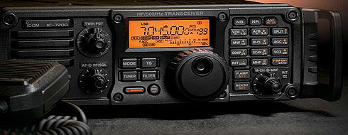
Non-voice high seas weather broadcasts and safety messages to mariners can be found by spinning your VFO dial to 8.472 MHz USB courtesy of WLO from Mobile, AL, which provides these transmissions continuously. Here on the East Coast it is received with regularity due to it’s strong signal.
Those of you who are neophytes to RTTY or just want to dabble then this is the place to be to try your hand at an old and venerable digital mode. The RTTY (RadioTeleTYpe) parameters used by WLO transmissions are 45.45 bauds, 170Hz shift. These are most commonly used by amateur radio ops too. If you’ve roamed the bands for RTTY signals you’ll find that most are encrypted with a few exceptions, one of which is WLO which is transmitting continuously.
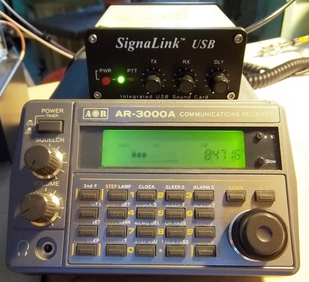
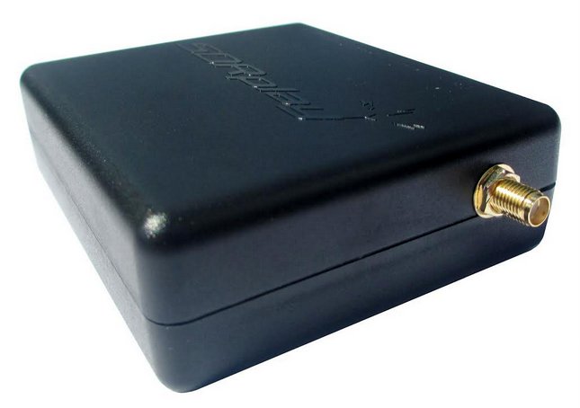
Tabletop SW radio set to WLO; SignaLink USB links radio to computer for decoding.
On 8.472 MHz you’ll receive weather information from different latitude/longitudes, along with other pertinent information to mariners such as high seas pirates (not radio pirates!) and naval maneuver areas that are important for ships to avoid. It makes for interesting copy.
To decode RTTY signals you’ll need a shortwave receiver with a BFO (Beat Frequency Oscillator), a way to pipe your radio’s audio into your computer’s sound card, and decoding software. There are several RTTY software packages out there, free, and my favorite is MMTTY. More info on MMTTY is at: http://hamsoft.ca/pages/mmtty.php . Old timers will find this software a snap to use, but newcomers will have to fiddle with the controls to get the decoding going. Below is a snapshot of MMTTY decoding a typical weather broadcast.
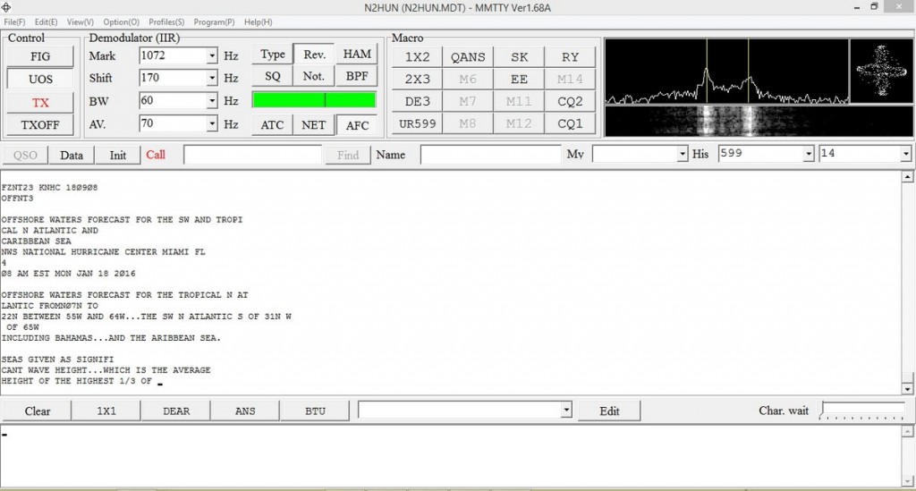
MMTTY dashboard with WX info. Cross-like indicator on upper right aids in tuning signal.
Another software available for decoding RTTY is Fldigi. Again, you’ll have to input the correct RTTY parameters such as baud rate and shift into the program along with adjusting your VFO carefully. It takes practice, but when the decoding is successful you’ll see Fldigi doing it’s thing as shown below. Both MMTTY and Fldigi have waterfalls displaying a visual image of the received signal. With practice you’ll be able to distinguish the different common RTTY shifts just by looking at the waterfall.
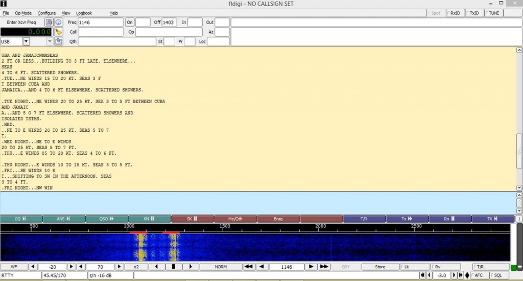
Fldigi in action with split screen; RTTY text above, waterfall below.
Now to Sitor B (Simplex Teletype Over Radio Mode B), another non-voice mode we can use to decode WLO transmissions. Sitor B sounds a lot like RTTY to the human ear, but requires different decoding software. WLO transmits weather information via Sitor B immediately after RTTY transmissions, switching back and forth, which makes for even more fun! Software that decodes Sitor B is available on the ‘Net as free downloads. One is MultiPSK, the other is YaND.
I like YaND (Yet another Navtex Decoder) which is used to decode NAVTEX (Navigational Telex) transmissions commonly found on 490 KHz and 518 KHz, but it works well for decoding Sitor B. There is a difference in the way messages are processed in NAVTEX versus Sitor B and for further information perform a Google search. But the fastest and easiest way to decode Sitor B transmissions from WLO is to fire up YaND. Below is a recent NAVTEX HF broadcast capture.
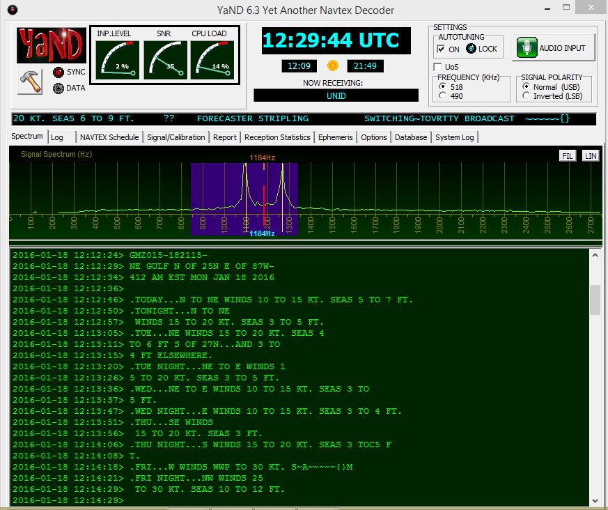
WLO HF WX broadcast for NE Gulf on 1/18/16 .
Well, hopefully some of you will be inspired to check out maritime weather/safety information found on WLO using RTTY/Sitor B/NAVTEX software. However, RTTY can also be found on the ham bands and on shortwave frequencies. Several RTTY stations from Germany are found on frequencies such as 11.039MHz and 14.467MHz. Their weather information format is quite different and will give you an idea of European weather conditions and allow you to practice your German. When not sending weather info they run a RTTY message loop below at 50bauds/425Hz shift.
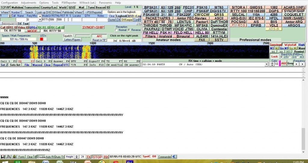
German RTTY station with message loop. Deciphered via MultiPSK.
In closing, make sure to also check out the NAVTEX broadcasts found just below the AM broadcast band on 490 and 518 KHz; using YaND or MultiPSK you’ll be able to receive these transmissions, but remember you’re not on HF, you are on MW (medium wave), where signal distances are shorter and present a greater reception challenge. YaND software has a NAVTEX broadcast schedule built in as seen below; you have to identify your specific NAVAREA or navigational area, then look at the times and frequencies to determine when to listen in. My QTH is in NAVAREA 4. Lots of interesting information is passed in these NAVTEX transmissions so listen in and have fun!
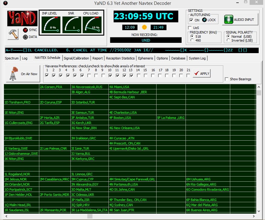
YaND NAVTEX schedule for various NAVAREAS.
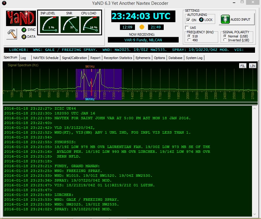
NAVTEX on 518 KHz from station VAR-9, New Brunswick, CAN. Messages begin with “ZCZC.
Mario Filippi (N2HUN), is the author of this post and a regular contributor to the SWLing Post. Click here to read Mario’s guest posts.

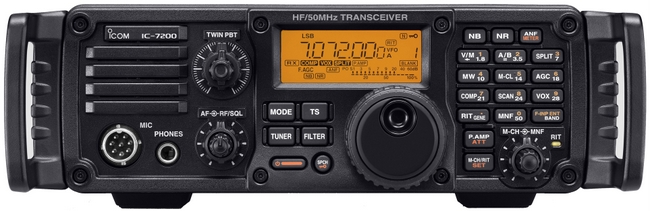 Many thanks to SWLing Post contributor Dave Zantow, who notes that the Icom IC-7200 general coverage transceiver is being discontinued.