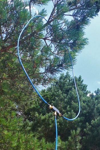
Photo via Unsplash
Many thanks to SWLing Post contributor, Steve Allen (KZ4TN), who shares the following guest post:
Tracking Down Radio Frequency Interference
by Steve Allen, KZ4TN
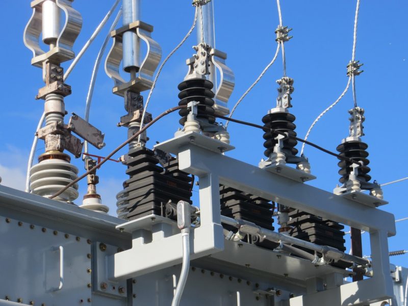
I first noticed the RFI in late November 2019 as a steady buzz at around S9. It was present over most of the high frequency spectrum. I waited until the second week of December to see if you would end on its own, no such luck. I put an HF rig in my truck and started driving around the area to see if I could find a potential source. About a quarter mile from my home is a 161 KVA substation operated jointly by the Tennessee Valley Authority and my local electrical utility. When I parked in the driveway outside of the gated substation the sound of the interference was very strong and blanked the HF spectrum. I called the phone number on the gate and after an explanation of why I was calling I was connected to a fellow radio operator. I explained the situation and he said he would bring the issue to someone’s attention and get back to me.
A week went by and I didn’t hear back from the TVA. I called the person I spoke with previously and he said that the individuals that he spoke with questioned the validity of my findings. He was very helpful but said he didn’t have much clout with the TVA, RFI investigations were not his area of responsibility. I told him I would be happy to meet with someone from the TVA and show them what I had found. I also said I would contact my local electric utility and see if they had an RFI detector so we could eliminate their equipment. My initial contact at the TVA said he would keep trying to get someone to take this issue on and work with me to investigate. I said I would call him back next week.
I then called the local utility company and talked to someone there who was familiar with these kinds of issues. The local utility company owns the output side of the equipment at the substation. He told me he was going to perform an infrared (heat) inspection of their equipment at the substation mid January as part of their annual maintenance and will also check the low voltage utility lines near the substation. I told him that I didn’t notice this RFI until after they had a power outage nearby. He said he would try and get over earlier and check the power lines that run along the streets and look into the power outage history for this area.
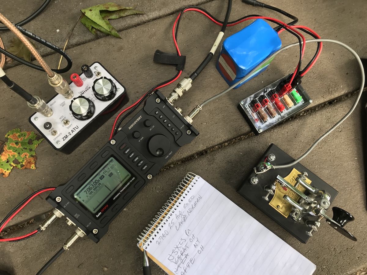
All during this time I kept a daily log of the RFI including time of day, frequency effected and S unit level. I also logged the weather conditions. To eliminate the electronics in my house as a possible source I connected my transceiver to a 12 VDC battery and shut off the mains circuit breaker, the RFI did not change at all. I also visited the ARRL webpage that provide information on RFI including recordings of known RFI:
http://www.arrl.org/radio-frequency-interference-rfi
The ARRL is the best source I have found in finding and fixing RFI.
By December 27th, no word back from anyone. I assumed that they were off for Christmas but decided to write a letter to the TVA as a follow up to what had happened so far. In early January I received and email from one of the TVA engineers who said he would contact a field engineer who would contact me. The next day I received an email from the field engineer who said he was going to be in the area on another job but would meet me at the substation.
So, of course as soon as I am making headway with finding the problem the RFI diminished to the point of not being a problem. By this time here in Northeast Tennessee the winter temps are in the 40s and the humidity is lower. For whatever reason, the RFI ended. I met with the field engineer and we agreed that if there is no RFI there is nothing to search for.
Fast forward to August, 2020. In June and July I had been operating digital, mostly FT8. I usually had the volume control at zero and as it was summer I was doing no shortwave listening. One day I decided to tune around the bands and found that the RFI was back as strong as it was during December at S4-S9 from 2-30 MHz. I emailed the principal engineer I had previously been in contact with at the TVA and he told me he would contact another field engineer and that he would come to my house with an RFI locator and start a thorough investigation. The next day I received an email from the field engineer and we scheduled a time for him come over.
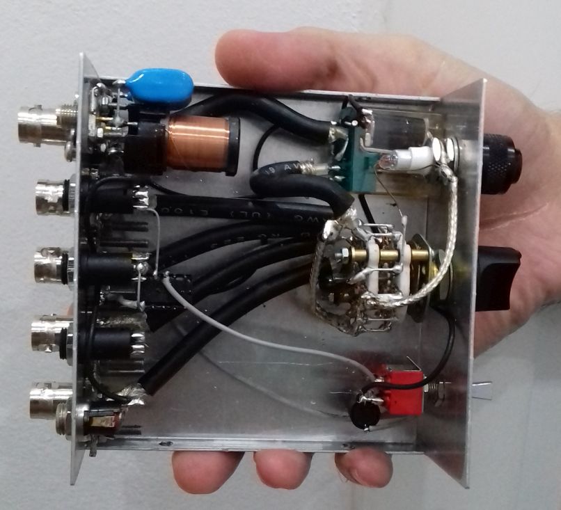
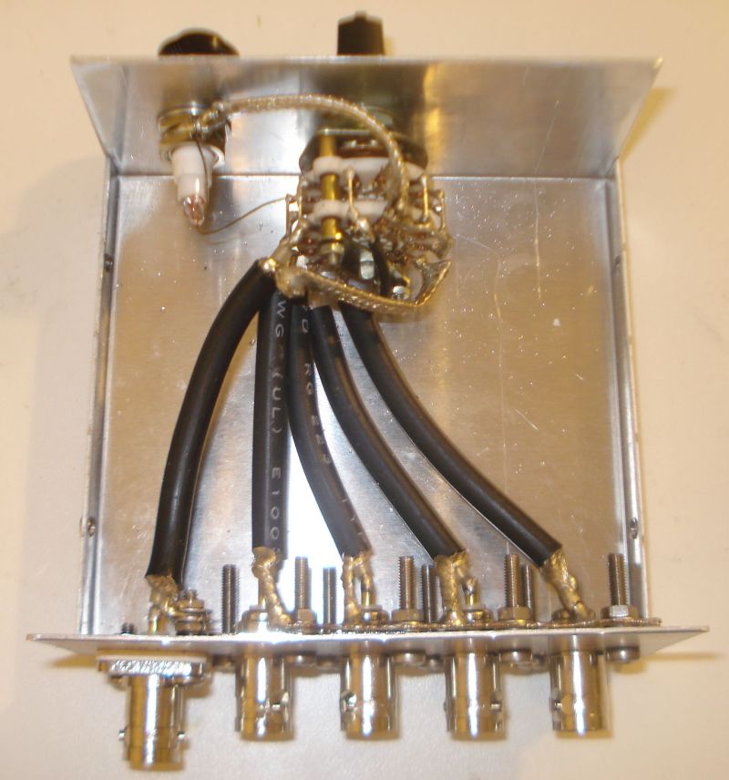
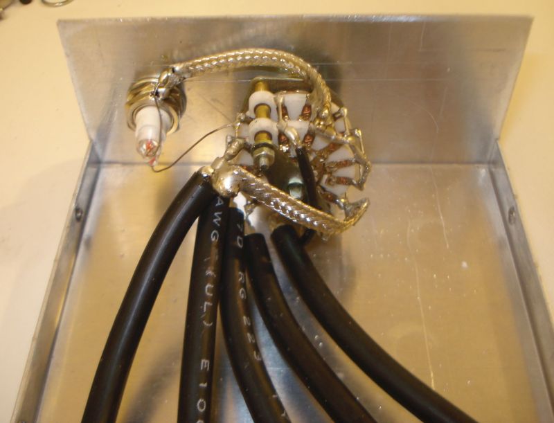
Upon his arrival he connected his RFI locator to my vertical antenna and tuned across the spectrum. The locator immediately displayed the signal. He captured an electronic image and said that he could now drive around the area and try and find a match. A hour and a half later he called and said he was unsuccessful and wanted to come back and make sure the signal was still present. Sure enough, it still displayed on his locator and he was puzzled why he could not find a similar signal while driving the area. He said he would send a copy of the recording to the TVA engineer and get back to me.
A few days later I heard back from him and he wanted to come over again and make another recording. I believe after discussing this issue with his supervisor he was going to use a different method of searching the area. After a couple of hours I received a phone call from the field engineer telling me that he thought he had found the source of interference. Using a parabolic antenna he had found two different utility poles that appeared to have defective lightening arrestors on them. Both are within a quarter mile of my QTH. These poles are the responsibility of the local electrical utility not the TVA. He said he would contact them and follow up with me in a few days.
In a couple of days the interference was very low to nonexistent. Shortly thereafter the engineer contacted me saying the local utility company had completed the repairs and wanted to know if the interference was still present. I said I hadn’t hear it in a couple of days and I would get back to him if it returned. A couple of weeks later I received an email from the field engineer detailing the incident, what he had done to locate the interference, and what was done to repair it. In his email he stated the service was provided at no cost by the TVA Right of Way and Elizabethton Electric Department through TVA’s Comprehensive Services Program (CSP). I am so appreciative of the Tennessee Valley Authority. The airwaves are now free of manmade interference and I am looking forward to another winter of operating and listening to shortwave radio. Here in the 21st century there are so many electronic devices that are capable of causing RFI. I am very thankful that my station is RFI free (for the time being).
Steve Allen, KZ4TN
Elizabethton, TN
Thank you so much for sharing your story, Steve. Only recently, we posted Emilio’s article about tracing interference to poorly made switching power supplies. Thank you for sharing how you approached your local utility company, in your case, to resolve your RFI!
Very encouraging! Readers note that you don’t always have to live with persistent RFI. If you know the source isn’t coming from within your home, sometimes it’s simply a matter of getting your local utilities company to investigate.