 The new 2022 “Belka” (generation 3) general coverage receiver
by 13dka
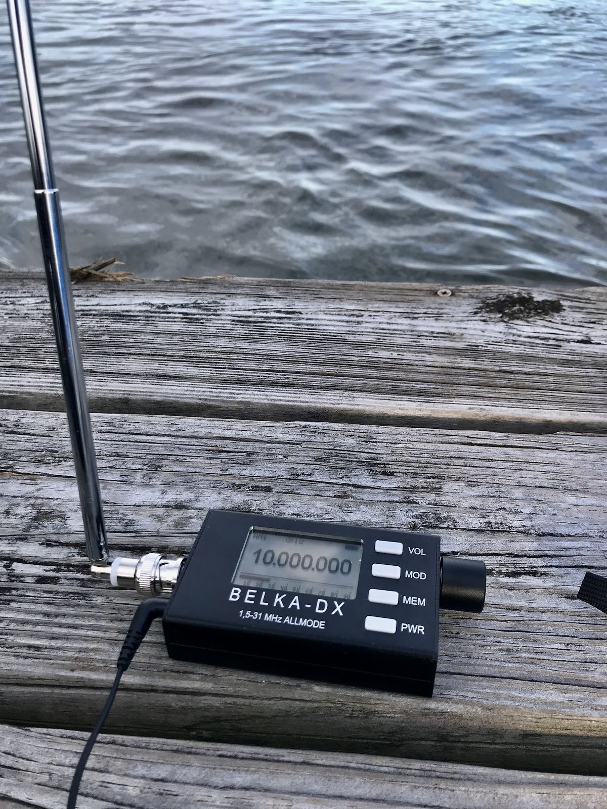
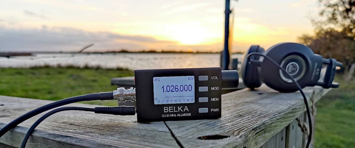
Since its introduction in 2019, the super-tiny Belka (back then called “Belka DSP”) shortwave receiver sure gained an enthusiastic followership among SWLs and hams. The main reason for this is certainly the way how the Belka is incredibly small yet playing in a different league than the various consumer grade, Chinese mass-production radios, particularly the DSP-based ultraportables: The Belka is an all-mode shortwave communications receiver with a completely different (direct conversion SDR) architecture, developed and produced by a radio enthusiast (Alex, EU1ME) in a small mom&pop shop in Belarus.
In case you’ve never heard about it amidst all the buzz about more popular brands, here’s the skinny:
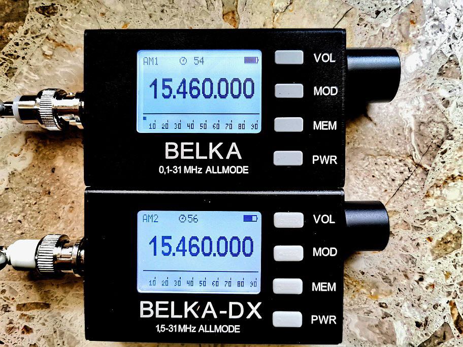
The Belka offers true allmode (including NFM and CW) reception with a proper 400 Hz CW filter and individual settings for the low and high filter slopes for AM, FM and SSB. It has an AM sync detector and comes with a 0.5ppm TCXO-controlled local oscillator for absolutely spot-on, calibration-free frequency precision and stability, which makes SSB or ECSS reception of broadcast stations a pure joy. The second iteration “Belka DX” brought a slightly extended coverage down to 1.5 MHz and an I/Q output for panadapter display and/or processing via your favorite SDR software.
All Belkas are quiet and very sensitive radios with a surprisingly robust front end, the filters are better and its AGC works like you’d expect it from a communications receiver, without the artifacts and distortion the DSP radios are infamous for, and of course smooth, non-“muting” tuning in variable steps down to 10Hz.
The Belkas have no built-in speaker (available as option tho) but really excellent audio on headphones and external speakers and they actually give my Icom IC-705 a run for its money in terms of reception quality, and they do that for up to 24 hours on a single charge of the internal Li-Ion battery. This stunning feature set is crowned by the best performance on a telescopic whip antenna ever – the Belkas have a high-impedance (>10 kOhm) antenna input optimized for this whip and taking it on a walk is (really!) like having a big rig with a big antenna in tow…
Despite all this goodness setting the Belka(s) quite fundamentally apart from most (if not all) current and former, even much higher priced portables and simultaneously putting it solidly into pricey tabletop territory, it hasn’t put Tecsun et al out of business for a couple of reasons: One reason is that it can only be obtained from Alex in Belarus, which is now often assumed to be impossible (it isn’t, more on that later). Another reason is that it doesn’t try to compete with aforementioned multiband radios from China, so there is no FM broadcast band and – until now – no AM BC band, but most owners and potential buyers particularly in the US really wished it had at least the latter. Well, Alex obviously heard us! After the Belka DSP and the Belka DX, the new Belka is just called “Belka”, so in order to avoid any ambiguity I’m going to refer to this model as “Belka 2022”.
What’s new?
The most prominent addition to the Belka 2022 is the extended 0.1-31 MHz coverage, the previous version only started receiving at 1.5 MHz. With LW and MW included, its “pseudosynchronous” detector (as featured in venerable radios from Harris, Racal or Drake), the great filtering and the great frequency precision for hassle-free ECSS reception are promising that the “squirrel” is now an ultra-ultraportable companion for MW DXers as well.