Shortwave listening and everything radio including reviews, broadcasting, ham radio, field operation, DXing, maker kits, travel, emergency gear, events, and more
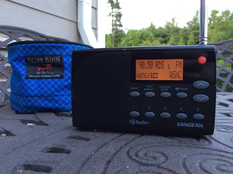
More broadcasters than you might realize are helping keep the ionosphere warm (and the power companies happy)
In the May 9 issue of Radio World, I reported on a recent power upgrade at TWR’s Bonaire AM facility that brought that station close to the half-megawatt level (440 kW), allowing the station to make the claim that it is the most powerful medium-wave (MW) operation in the Western Hemisphere. After the dust settled, I thought it might be interesting to poke around a bit in the data available to see if they have a close (or even not-so-close) contender for second place for this title.
With only a few exceptions, U.S. stations have been capped at 50 kW since this power level was authorized by the Federal Radio Commission in the late 1920s. Powel Crosley Jr.’s WLW 500,000 kW 1930s “experimental” operation is one very well-known example, as it received a lot of publicity during the five years or so during it operated before being powered down. However, there was another much less well-known superpower operation during that period (it actually beat WLW to the punch by putting 400,000 Watts on the air about three years before Crosley was ready to belt out his hundreds of kilowatts).
[…]Surprisingly, there is one U.S. AM station that has the necessary paperwork and equipment to operate at 100 kW full-time. However, it’s not listed in the FCC’s AM database. I’m referring to the VOA’s “Radio Martí” in Marathon, Fla. which operates on 1080 kHz.
The VOA station (it sports no call sign) appears to be the only operation in its class in the U.S. and Canada, but it if you cross the border into Mexico, you’ll find “muchas estaciones de radio” that emit lots more than a puny 50,000 “vatios.”[…]
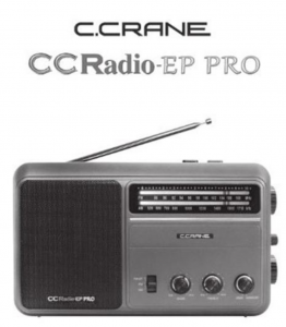
Remember the American television game show To Tell The Truth? This very long-running show challenged four celebrity guests and viewers to identify the real “central character” in the midst of two impostors.I was reminded of this game show when attempting to tell the difference between the original and recently updated versions of C. Crane’s CCRadio-EP Pro receiver when viewing the front panels. If there’s a difference, I can’t spot it! You need to turn around the radios to see the new EP-Pro’s key feature: switchable 9 kHz/10 kHz tuning steps.
The only clue to the newest version of the CCRadio-EP Pro is the 9/10 kHz tuning switch on the back panel.
I recently met with a good friend and radio hobbyist from Oregon to compare a few selected portable radios, FSL (Ferrite Sleeve Loop) antennas, and the newest low-noise Wellbrook ALA100LN module that was introduced just a few weeks ago. I was particularly interested in a head-to-head match-up of my friend’s original EP-Pro versus my newly arrived EP-Pro (9 kHz/10 kHz steps) version.
I’m looking forward to Thomas’ usual thorough review of the new CCRadio-EP Pro, but I want to offer a few observations of medium wave tuning after my time with the two models:
On very weak daytime MW signals, the radios are equally sensitive except on higher frequencies where the new model excels to a moderate degree. It’s enough of an advantage to make the difference between catching an ID or not on a low, DX-level signal.
The new EP-Pro feels more accurate–and simply more enjoyable–to tune, thanks to the elimination of false “peaks” surrounding the main signal. This is a BIG plus for the new radio, and frankly the CCRadio-EP should have performed this way from the start. Kudos to C. Crane for correcting this problem, but I can understand why the original version was brought to market with the odd tuning quirk. It isn’t a deal breaker for most non-DXing purchasers.
I could not find an instance of soft muting on either radio. I listened for a while to signals barely above the noise floor, and never did audio “cut in and out” suddenly, a clue to soft muting. Both receivers are very useful for chasing weak MW stations…but the new version is highly preferred for ease of tuning because of the lack of false audio peaks.
With the tuning working way it should, medium wave channels “snap” in and out as you slowly tune. This took a little getting used to, but after a while I began to appreciate the sense of exactness with the newest CCRadio-EP Pro.
Fast excursions up or down the band (either radio) will blank the audio, recovering when you stop tuning or slow down. I believe this is simply a case of exceeding the AGC’s recovery time, not soft muting. It’s easy to live with, but granted the effect is not one of smoothness as found on traditional, non-DSP analog receivers. Successful DXing takes a slower approach anyway when scanning the band; casual listeners may be more annoyed by either version of the radio if they are used to very quick knob-cranking.
The Twin Coil Ferrite “AM Fine Tuning” control works well on both units, and gives significant gain to weak signals on either extremity of the band. I love this feature; it makes digging out the weak ones a lot more fun!
So, should you buy the newest CCRadio-EP Pro with the 9 kHz/10 kHz steps?
If you already own a CCRadio-EP Pro and are fine with the false tuning peaks and have no desire for the 9 kHz MW step option–keep your radio! Only on high band does the new model have a sensitivity edge. Especially don’t make the jump if you’re a casual listener and listen only to a handful of local stations, or a single distant station.
If you do not own a CCRadio-EP Pro yet, but are in the market, definitely buy the newest version. Be aware that you can only be assured of getting the newest model if you purchase directly from C. Crane. Amazon does not yet carry the newest version according to some reports.
If you’re a radio junkie and just have to have both…go ahead…we understand!
I also made a short video comparison of the new EP Pro versus the top-ranked Panasonic RF-2200 on medium wave:
https://www.youtube.com/watch?v=zbZ-06uBsNs
Guy Atkins is a Sr. Graphic Designer for T-Mobile and lives near Seattle, Washington. He’s a regular contributor to the SWLing Post.
Many thanks to SWLing Post contributor, Gary DeBock, for sharing the following guest post:
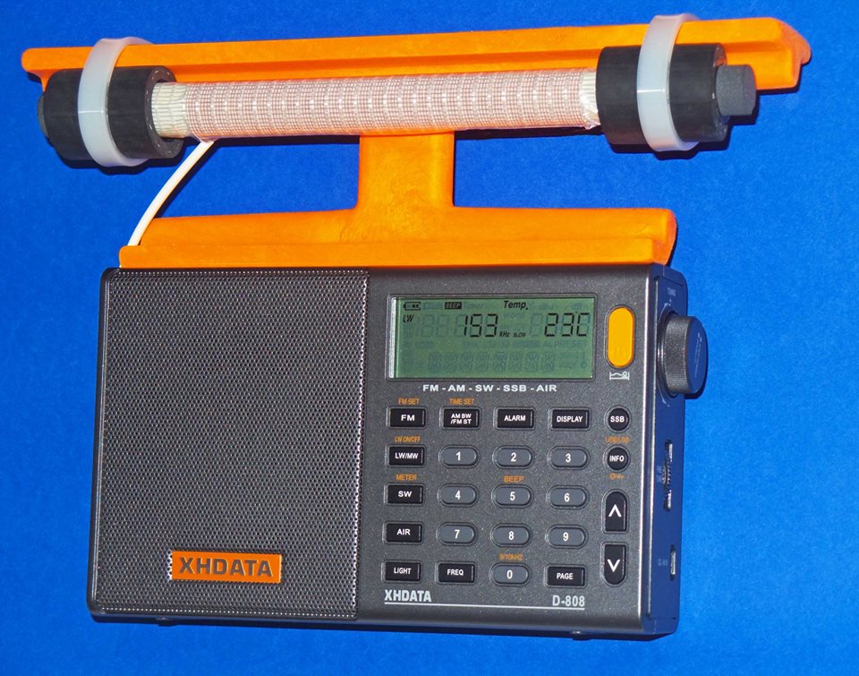
Supercharging the XHDATA D-808
Installation of High Performance AM and LW Loopsticks
By Gary DeBock, Puyallup, WA, USA, September 2018
Introduction
As a stock receiver the Chinese-made D-808 AM-LW-FM-SW-AIR portable is a very capable performer, with AM reception superior to that of any current Ultralight model, and impressive FM reception as well. The radio was certainly “inspired” (to use a generous term) by the C.Crane Skywave SSB model, which coincidentally was manufactured in the same part of China by C.Crane’s Redsun partner—with the first units going out the door a few months before the D-808 came into existence.
Because foreign intellectual property is routinely copied in China with no punishment from the government, XHDATA essentially had the chance to copy all the good points in the Skywave SSB design and improve upon its weak points as well. The only precaution that XHDATA took after this wholesale design appropriation was to forbid direct shipments of the D-808 from China to North America—presumably to avoid a copyright lawsuit by C.Crane. As such, the first D-808 models were sold to the rest of the world around January of 2018 at a price about half that of the Skywave SSB, while North American DXers were told that since the model couldn’t be shipped to the USA or Canada, they were out of luck.
Of course some D-808 models did make it into North America, where it was found to be a very capable portable with astonishing value for the price. Finally around March, an enterprising Chinese eBay seller came up with a plan to ship the model to North America through Israel, thereby skirting around XHDATA’s direct shipment prohibition. As of late August this eBay seller (harelan ecommerce) has already sold 62 of the D-808 models this way, even though he charges a premium for shipment to North America. Whether this single supply source will continue to serve North American customers is currently unknown, but out of the 7 models that I have purchased from him there hasn’t been a single D-808 model with any issues– despite the apparent lack of any manufacturer’s warranty offered on the radio.
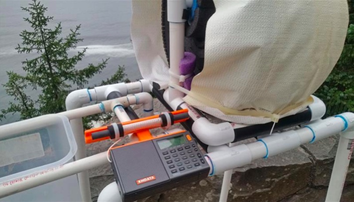
Despite the D-808’s rather dubious design pedigree there is no doubt that the Chinese engineers (or reverse engineers?) did a superb job in creating an awesome radio for the money. Besides directly copying the Skywave’s SSB design and controls, XHDATA also made significant improvements, including a longer loopstick (providing clearly superior AM sensitivity), a much more powerful audio amplifier (correcting a serious shortcoming in the Skywave SSB) and a much lower price (about half that of the $169.99 Skywave SSB, for models shipped outside North America). Another great advantage for someone wishing to perform this loopstick upgrade are the perfectly located, highly accessible Litz wire connections on the RF circuit board—apparently used by the Chinese engineers to conveniently test out various loopsticks, and retained in the final product. The radio’s high quality construction and survivability in adverse conditions were proven repeatedly over the summer here, with the model surviving accidental exposure to a 104 degree (43 degrees C) car trunk temperature, exposure to moderate rain, repeated travel bumps, and use as the main receiver during a 9-day DXpedition to a plunging ocean side cliff in Oregon state. The 3.7v lithium-ion rechargeable battery provides superior run time for extended DXing sessions, and is included in the D-808 shipping package, along with a USB cord to charge the battery, a plug-in wire antenna (for FM,SW and AIR), a vinyl carrying case, and a pretty basic English instruction manual.
One thing you will NOT find supplied with the D-808 is a warranty card– either in the shipping box, or online. This is pretty standard practice in China, incidentally, where concepts like refunds and warranties aren’t generally part of customers’ expectations. This doesn’t necessarily mean that XHDATA won’t repair obvious problems in a new D-808, but it does mean that they aren’t assuming the obligation to do so. I have heard from one North American purchaser who received a new D-808 with a defective speaker, and he is still waiting for the model to be repaired (after paying the shipping charge to send it back to China). Each individual purchaser must decide whether or not this lack of any warranty is a deal breaker. But if you are looking for a final reason to perform this loopstick transplant, why not consider the fact that you will not be violating any manufacturer’s warranty by doing so??
Realistic Expectations
Although this 7.5” loopstick upgrade will certainly make your D-808 far more sensitive than the stock model on Medium Wave or Longwave, it is not designed to compete with large (2’ sided or larger) inductively coupled box loops, or any of the new FSL antennas. The sensitivity upgrade will boost the D-808’s MW band weak-signal performance up to the level of classic portables like the ICF-2010 and RF-2200; however, and since the D-808’s DSP-enhanced selectivity will generally exceed that offered by these classic portables, the overall DXing capability in the AM mode could be considered slightly greater. The D-808 does have SSB capability, although it lacks the SSB tuning convenience offered by the ICF-2010 and RF-2200. It also lacks the ICF-2010’s superb Synch detector, a big advantage in weak signal DXing. But in portability, versatility and DXing value for the price, the “Supercharged” D-808 is a real winner.
Project Overview
This construction article will provide the builder with step-by-step instructions to upgrade the XHDATA D-808’s loopstick to a much more sensitive, externally-mounted 7.5” Medium Wave or Longwave loopstick replacement. Both the Medium Wave and Longwave 7.5” loopstick designs have been thoroughly tested and proven effective in actual DXing by hobbyists other than the author, and as long as the instructions are followed carefully, this relatively inexpensive modification will provide a major improvement in the D-808’s weak-signal reception capability.
This modification project involves close-order soldering on the D-808’s circuit board, and should only be attempted by builders with reasonably good eyesight, good hand coordination and soldering experience. The project also calls for the use of a precut plastic loopstick frame to attach the antenna to the top of the D-808’s top back cabinet surface, and the construction of this precut plastic frame requires either the use of a 12” (or larger) power miter saw, or some rather lengthy cutting with a hacksaw. Use of a power miter saw SHOULD NOT be attempted by those without serious power tool experience! The author assumes that only qualified power tool operators will attempt to use a 12” miter saw to cut these frames quickly, and that other builders who wish to construct them will use a hacksaw. As such, only basic cutting instructions are provided for the 12” power miter saw users, while detailed instructions are provided for the hacksaw users. To assist builders who are not qualified to use power tools, the author has prepared a LIMITED number of these precut plastic loopstick frames on a power miter saw, which will be offered at cost to these builders on a first come, first served basis.
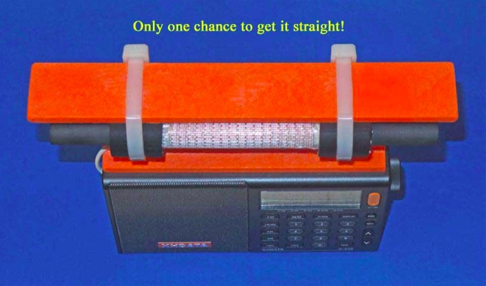
A final warning is in order concerning the step of gluing the precut plastic loopstick frame to the D-808’s top back cabinet surface. Although this step is not dangerous, it is pretty tricky. Since the superglue “grips” very rapidly, you will only get one chance to ensure that the frame is straight, and centered on the D-808’s top cabinet surface. Do yourself a favor, and make multiple “dry runs” to practice this important step before applying the glue! Failure to take this step seriously will probably result in a crooked loopstick frame—which will hold the antenna just fine for DXing purposes, but which will be an eternal reminder to the DXer (and everyone else) of the hazards of haste.
Construction Parts Required
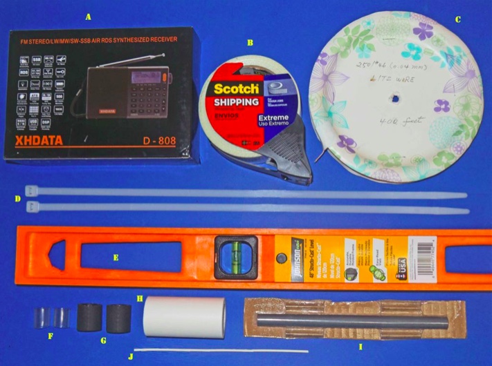
This 7.5” loopstick D-808 construction article will guide you through the assembly of either a 7.5” Medium Wave loopstick D-808 or a 7.5” Longwave loopstick D-808, so make sure that you order the parts necessary for construction of your chosen model. The picture above shows the parts that will be necessary for construction of either model, but the Litz wire and 7.5” ferrite rod components differ according to whether you are building the Medium Wave or Longwave model.
A) XHDATA D-808 Receiver, currently available to North American purchasers (for $112.87 + $10. Click here to search eBay.
B) Scotch brand “Extreme” strapping tape (any size roll)
Miscellaneous: One packet of Duro Super Glue (.07 ounce size), solder, 25w (low heat) soldering iron, hacksaw (or power miter saw), screwdriver set, sandpaper, needle nose pliers, diagonal cutters
D-808 Radio Preparation
Before starting the modification give the radio a thorough test on all bands, ensuring that all the stock model functions work properly, and that there are no issues with the display, speaker, headphone jack, battery or charging system. It’s also a good idea to run a daytime DX band scan on the AM or Longwave band (for whichever band you plan to construct an upgrade loopstick) and document the results—to use as a benchmark for the upgrade loopstick’s performance.
Step-By-Step Construction
Antenna Frame and 7.5 inch Loopstick Preparation
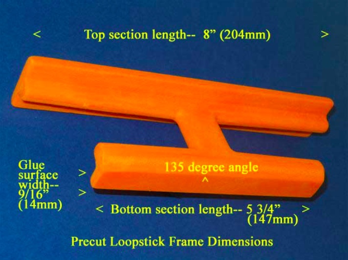
1) Refer to the photo below. Using the “Supercharging the Tecsun PL-380” article (posted at http://www.mediafire.com/file/du3sr5cd9thqvau/7.5inch-LS-PL380.doc/file or available directly from the author) carefully prepare the orange loopstick antenna frame according to construction steps 1-9, EXCEPT note that the lower (glue surface) edge of the antenna frame should be cut to a length of 5 3/4” (147mm), NOT 5” (127mm) as described in the PL-380 transplant article. Pay close attention to the safety precautions concerning power tool usage, and DO NOT attempt to use a power miter saw unless you have SERIOUS power tool experience!
2) If you are constructing an AM (Medium Wave) loopstick, follow construction steps 10-16 in the PL-380 transplant article to construct the antenna. If you are constructing a Longwave loopstick, follow construction steps 10a-16a in the PL-380 transplant article to construct the antenna. If you are constructing both loopsticks, MAKE SURE that the ferrite rod and Litz wire are only used in the antennas for which they were designed. Mixing up these items is very easy, and such a mistake will make both loopsticks perform like clunkers.
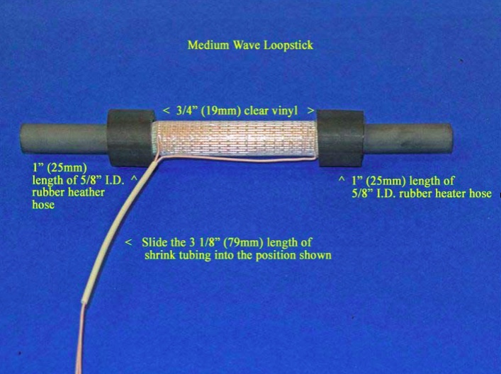
3) After construction of either the AM or Longwave loopstick, follow the instructions in steps 29 and 30 of the PL-380 transplant article to install a piece of 3 1/8” (79mm) shrink tubing, EXCEPT note that this length is slightly longer than the 3” (76mm) length called for in the PL-380 article.
4) Refer to the photo below for the following three steps. [NOTE: Although this photo shows the AM (Medium Wave) loopstick, the procedures in this step are the same for the Longwave loopstick, although the position of the rubber hose lengths and clear vinyl inserts will be closer to the ends of the ferrite rod]. Carefully slide the length of 3 1/8” shrink tubing into the position shown, ensuring that there are no Litz wire kinks or bends inside the shrink tubing.
5) Take the two 3/4” (19mm) clear vinyl inserts and slide them onto the ferrite rod ends, twisting them up against the border of the Scotch “Extreme” tape ends to lock the tape in place under the vinyl inserts. Ensure that the clear vinyl inserts do not touch any Litz wire leads or coil turns.
6) Slide the 1” (25mm) lengths of rubber heater hose over the clear vinyl inserts until the appearance of the loopstick resembles the above photo. Ensure that the rubber hose sections also do not touch either the Litz wire leads or any coil turns. Finally, place the completed loopstick in a safe place until it is called for in Step .
Radio Disassembly
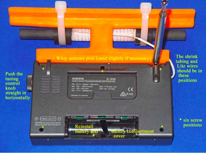
7) Refer to the photo above for this step. Remove the battery from the radio, and using a Jeweler’s Phillips screwdriver of the correct size, remove the six identical screws in the positions shown (NOTE: These screws have a tendency to stick inside their slots, even when the slots are turned upside down. If you cannot remove all six screws it’s not a major problem, but at least ensure that the screws are completely loose in their slots, and that you don’t lose any of them during the remaining steps). Grasp the tuning knob, and pull it out horizontally in a completely straight manner to remove it from the radio. Ensure that the battery, tuning knob and all removed screws are placed in a safe place until the radio is reassembled.
8) Carefully separate the front and back cabinet sections and place them down in the position shown in the photo below. Note that the front and back sections of the radio are connected by a ribbon wire plug-in system– ensure that this plug remains securely inside its slot at all times, and that no great stress is placed on the speaker wires.
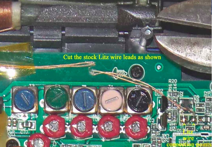
9) Refer to the close up photo below, and note the position of the two Litz wire soldering points on the circuit board (in the lower right corner of the photo). Using diagonal cutters, cut the two Litz wire leads at the position shown, UNLESS you wish to salvage this stock loopstick for other projects—in which case you should desolder the entire lengths of the Litz wire leads from the circuit board at the positions shown in the lower right corner (NOTE: The stock loopstick is of a fairly good design, and has an inductance that would be compatible with any DSP-chip Ultralight radio, providing an AM sensitivity boost in the process).
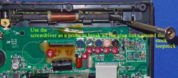
10) Refer to the photo below. Using a flat Jeweler’s screwdriver with a 1/16” blade, carefully probe around all four sides of the stock loopstick to break all of the glue bonds. Work slowly and carefully around the perimeter of the ferrite rod, including the plastic covers on each end. Once most of the glue bonds have been broken the ferrite rod will begin to shift around as you break up the few remaining bonds, but until this point work slowly and patiently to break up the glue.
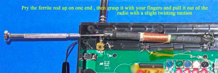
11) Refer to the photo below. Using the flat Jeweler’s screwdriver, once all of the glue bonds have been broken and the ferrite rod is loose in its slot, lift the ferrite rod out of its slot on one side by prying up under the plastic cover on the end of the ferrite rod. Ensure that the Litz wire leads have either been cut or desoldered from the circuit board, then grasp the ferrite rod with your fingers and pull it completely out of the slot with a slight twisting motion.
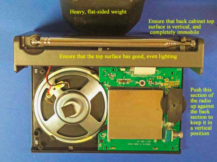
12) Remove the wrist strap, and refer to the photo below. Carefully pick up the two sides of the radio and place the back section in a vertical position as shown, with a heavy flat weight (barbell, or other heavy flat item) pressing up against the back cabinet section to keep it in a vertical position. Ensure that there is adequate, even lighting on the top cabinet section for the gluing process in the next step, and that the back cabinet surface will not shift around as you make the gluing “dry runs,” and perform the actual gluing of the loopstick frame to the top of the cabinet.
13) Take the previously prepared orange plastic loopstick frame, and ensure that its bottom glue surface is completely smooth and flat, with no uneven ridges on the edges of the glue surface (remove these with fine sandpaper, but ONLY on the ridges, and not on the rest of the flat glue surface). Using a damp paper towel, wipe the top cabinet glue surface and the loopstick frame glue surface to remove any dust or debris, then wipe them again with a dry, clean paper towel to ensure that they are both completely dry.
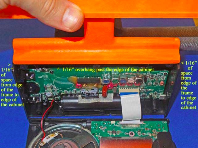
Take the loopstick frame and gently slide the frame over the top cabinet surface to ensure that both surfaces are smooth and flat. Refer to the photo at the top of the next page. Ensure that there is even, bright lighting on the top cabinet surface, and make several “dry runs” to place the loopstick frame in the exact center of the top cabinet surface (with 1/16”, or 1.5mm of space between the frame ends to the cabinet ends), and also 1/16” (1.5mm) of overhang above the front edge of the cabinet’s glue surface (NOTE: if you wish to simplify the process by lining up the front edge of the loopstick frame with the front edge of the cabinet’s glue surface it will still provide an acceptable result, but you will need to do some minor sanding of the whip antenna’s plastic slot post, as shown in the photo below. In either case, make repeated “dry runs” with the loopstick frame to practice placing it in the exact center of the top cabinet’s glue surface, since you will only get one chance to place it in the proper center position once the superglue is applied.
NOTE: The back of the loopstick frame has a beveled surface to permit full operation of the radio’s whip antenna after the frame is glued on the top of the cabinet surface. If the loopstick frame is glued with a 1/16” (1.5mm) overhang in front of the front edge of the cabinet surface then the whip antenna should have enough space for free operation. The alternative is to glue the two front edges lined up with each other to simplify the gluing process, in which case minor sanding may be required on the whip antenna slot post, as shown in the photo below.
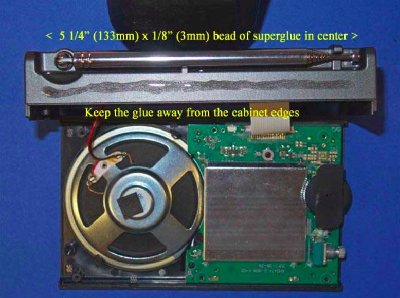
14) After making multiple “dry runs” and becoming familiar with accurate placement of the loopstick frame on top of the cabinet, refer to the photo at the top of the next page. After once again ensuring that the back cabinet section will not shift around during the gluing process, take the Duro superglue packet and apply a thin (1/8”, or 3mm) bead of glue along the center of the cabinet’s glue surface, extending it 5 1/4” (133mm)long, with equal spaces on both ends (as shown). While sighting the two sides place the loopstick frame carefully down in the correct center position as practiced previously, with the 1/16” overhang if desired. If satisfied with the position, press down on the frame to lock the two surfaces together securely. Usually the frame may be shifted around slightly within 1 or 2 seconds of placing it on the superglue, so use this brief time to promptly shift the frame to a straight position, if necessary. After a couple of seconds, though, you will need to be satisfied with whatever position the frame has ended up with (regardless, it will still hold the loopstick just fine, for DXing purposes).
15) After the loopstick frame is securely placed and locked on top of the D-808’s cabinet surface, place downward pressure on the loopstick frame along its length in order to ensure a tight glue bond throughout the entire top cabinet surface. Continue this process for about one minute, and sight both ends of the loopstick frame to ensure that they are both completely flat against the D-808 cabinet.
16) Inspect the front and back edges of the loopstick frame’s border with the D-808 cabinet for any glue seepage, and if any is found, remove it promptly with the 1/16” flat Jeweler’s screwdriver blade. Glue should not be allowed to run past the frame edges. This completes the process of gluing the frame to the D-808 cabinet.
7.5” Loopstick Installation
17) [NOTE: The installation procedures of the Medium Wave (AM) and Longwave loopsticks are identical, except that the plastic tie wraps and rubber hose sections are closer to the ends of the ferrite rod in the Longwave version. The following photos are for the Medium Wave (AM) version, but Longwave loopstick builders should follow the same steps, while referring to the Longwave model photo in the “Operation” section as a guide]
Refer to the photo below. Carefully take the previously prepared 7.5” loopstick and hold it in the position shown—in its slot, centered in the middle of the orange antenna frame, with the shrink tubing and Litz wire leads running down to the left. Take the two plastic tie wraps and install them in the position shown, centered over the rubber hose sections on the loopstick, while ensuring that no Litz wires or shrink tubing is bound under the plastic tie wraps.
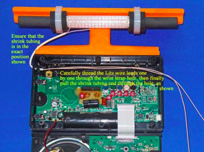
18) Refer to the photo below. Lay the two cabinet sections down flat as shown, ensuring that the Litz wire shrink tubing is in the exact position shown (if it isn’t, carefully slide it along both Litz wires until it is in this exact position). Carefully thread one Litz wire end through the empty wrist strap hole, then thread the other Litz wire end through the hole, as shown. Finally pull on the two Litz wires together from the right while guiding the end of the shrink tubing into the empty wrist strap hole, and pull a short section of the shrink tubing through the hole (as shown) to protect the Litz wire insulation from friction damage.
19) Refer to the photo below. Using the previous procedure to install shrink tubing (which is described in the PL-380 transplant article) install a 2.5” (63mm) length of shrink tubing over the two Litz wire ends, and shift the shrink tubing into the position shown in the photo. After this is done cut the two Litz wire leads to the lengths shown in the photo (NOTE: make sure that the ends of both Litz wires are cleanly cut, not frayed and at the minimum diameter before attempting to insert them into the shrink tubing. The process is much easier when the Litz wires pass smoothly through the shrink tubing).
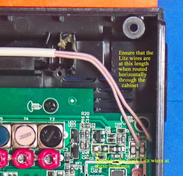
20) Refer to the close up photo below. Using a low heat (25w) pencil-type soldering iron, remove the two stock Litz wire leads at the positions shown, taking care not to use excessive heat, or touch the adjacent components. Ensure that the new Litz wire leads are at the length shown when the leads are in a horizontal position throughout the cabinet, and cut them to this length if they are not.
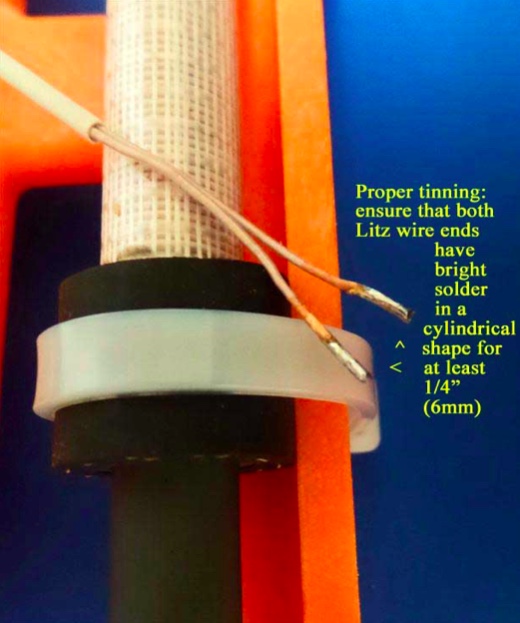
21) NOTE: When tinning the 250/46 Litz wire it is essential that all of the individual Litz wire strands be completely soldered together for a length of at least 1/4” (6mm), with bright, shiny solder around the circumference of the Litz wire ends for this minimum (1/4”) length. The Litz wire must be heated with a clean, hot soldering iron around its circumference in order to melt the solder properly for this step]
Refer to the photo above. Pull the Litz wires up out of the previous position, and place a clean rag underneath them (on top of the circuit board) to completely protect the circuit board from any solder which might accidentally drop down during the tinning process. Using your hot 25w soldering iron melt a generous amount of solder on its tip, and work the soldering iron tip slowly and patiently around the circumference of each Litz wire end until there is a bright, shiny solder length of at least 1/4” (6mm) in a cylindrical pattern at the end of each Litz wire. When doing this, take great care not to allow any solder to drip down onto the circuit board below (i.e., make sure that your rag completely covers the circuit board). The final appearance of your Litz wire lead ends should resemble those in the photo.
22) When your Litz wire lead ends resemble the photo above, cut the soldered portion down to a length of 3/16” (5mm) and observe the appearance of the end of the Litz wire. It should have a bright, solid circular shape, with no gaps or individual Litz wires showing. If not, reheat the end of the Litz wire while adding some solder, and repeat this step.
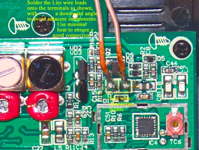
23) NOTE: The Litz wire connection points on the circuit board are surrounded by other important components. It is important to avoid solder drips on these components, or solder bridges to their leads. Solder the Litz wire leads down at an angle to avoid these surrounding components, and use the minimum amount of heat and solder to ensure good electrical connections)
Refer to the close up photo above. Following the precautions described, solder the two Litz wire leads down onto the circuit board at an angle, as shown in the photo. After soldering, make a close visual inspection to ensure that there are no solder bridges across the Litz wire connections, or nearby components. The remaining length of the Litz wire leads should be routed in a horizontal manner to the wrist strap hole.
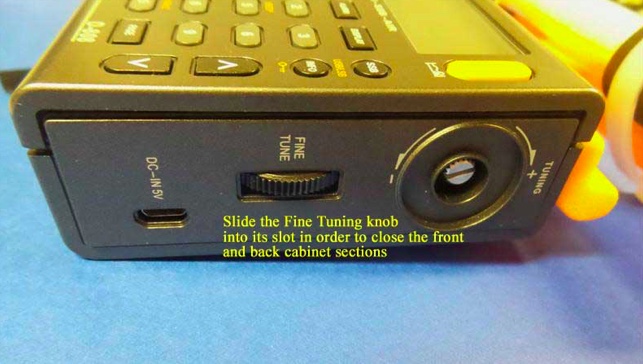
24) Carefully pick up the front and back cabinet sections, and hold the back cabinet section fairly close to the front section (as the radio would normally be oriented, when assembled). Refer to the photo below, and carefully insert the “Fine Tuning” control thumbwheel from the front cabinet section into its slot on the back cabinet section in a sideway movement. This will allow you to fully close the front and back cabinet sections in the next step.
25) Refer to the photo below. Pick up the two cabinet halves and carefully snap them together (this action should not require any great force). Place the radio face down in the position shown (with a soft surface underneath, for protection), and using the Jewelers Phillips screwdriver of the correct size, carefully screw in the six screws that were loosened previously, starting with the screw near the whip antenna post (you should pick up the radio temporarily and hold the two cabinet sections together tightly at this corner, as you do this).
After all six screws have been retightened take the Tuning control knob and press it back onto its shaft in a straight horizontal motion. Finally, reinstall the battery and battery compartment cover to finish up the reassembly.
TESTING AND OPERATION– MEDIUM WAVE MODEL
This 7.5” transplant loopstick is designed to provide a major boost in sensitivity from 530-1700 kHz, and if the antenna is working properly both the weak signal reception and the radio’s nulling capability should be greatly enhanced. It is normal for the antenna to receive more background noise on the low band frequencies, although the sensitivity boost should be substantial across the band.
The construction design of the orange antenna frame allows full usage of the whip antenna for checking SW parallels of MW-DX stations, although if you chose to glue the antenna frame flush with the front of the back cabinet surface to simplify the gluing process, you may need to sand the whip antenna slot post slightly to allow free movement of the whip antenna (see step #13).
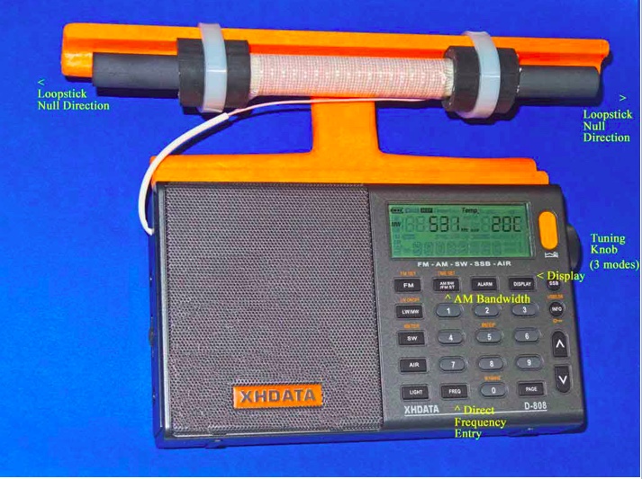
In the photo above, some of the important controls for Medium DXing are highlighted. The AM Bandwidth control allows you to choose multiple DSP filtering selections to enhance selectivity as desired, with the narrowest filtering (1 kHz) providing both the sharpest selectivity and the best weak-signal sensitivity. However this 1 kHz setting also has the poorest audio fidelity, with the higher audio frequencies typically cut off by the DSP filtering. As such, for regular DXing far away from strong local pests, the other AM Bandwidth settings may be more suitable. The Direct Frequency Entry key allows you to manual enter in any MW frequency, to which the radio will shift once the numbers are pressed on the keypad. The Tuning knob has three different modes, which can be toggled by pressing the knob horizontally. The first mode is tuning in either 9 kHz or 10 kHz steps (depending on which of these step you have selected), while the second mode is tuning in 1 kHz steps. The third mode is to lock the frequency in place. Pressing the knob again will return the tuning to 9 or 10 kHz steps.
The XHDATA D-808 has multiple display functions, which can be toggled by the indicated key. The first option is the temperature in either Centigrade or Fahrenheit (depending on your pre-set preference), while the second option is the alarm time. The third option is the current time (which you need to set according whether you prefer UTC or local time), while the fourth option is the received signal strength in both dBu and dB.
The supplied 3.7v lithium ion battery has superior run time, and may be easily charged using the supplied USB cable to either a computer or AC outlet (with the appropriate adapter). As reported in various posts throughout this year, the D-808 model has rugged construction with an excellent record of survival under tough conditions, including hot summer days, moderate rain exposure and extended usage as the main receiver during a 9-day ocean cliff DXpedition in Oregon—performing flawlessly at all times.
Conclusion
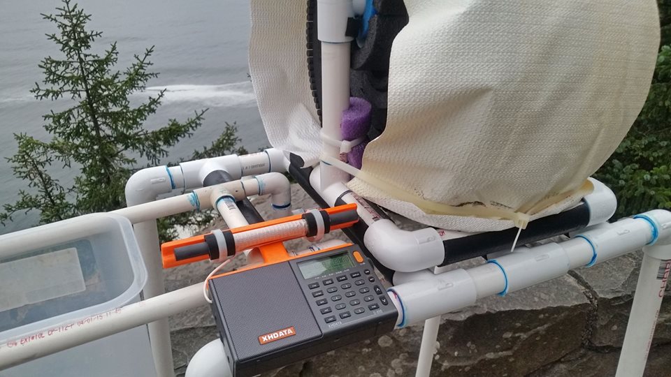
It is the author’s sincere hope that this “Supercharged” D-808 model will bring you a lot of DXing fun during travel, as well as at other times. When conditions are good you should never underestimate this enhanced model’s potential of receiving awesome DX beyond your expectations—as an example, here is the stand-alone performance of a 7.5” loopstick D-808 in receiving 1017-A3Z in Nuku’alofa, Tonga (10 kW at 5,632 miles/ 9,063 km) on the ocean cliff near Manzanita, Oregon at 1301 UTC on August 8th of this year:
Not only Tonga is received, but even the Australian horse racing station 1017-2KY in Sydney (5 kW at 7,630 miles/ 12,280 km) is received as a weak co-channel in the middle of the recording. My hope is that you all will be so lucky with your new Supercharged D-808!
73 and Good DX,
Gary DeBock (in Puyallup, WA, USA)
Absolutely amazing! Thank you for taking the time to put this procedure together and describing the process in such fine detail, Gary! Hats off to you!
Click here to read all of Gary DeBock’s posts on the SWLing Post.
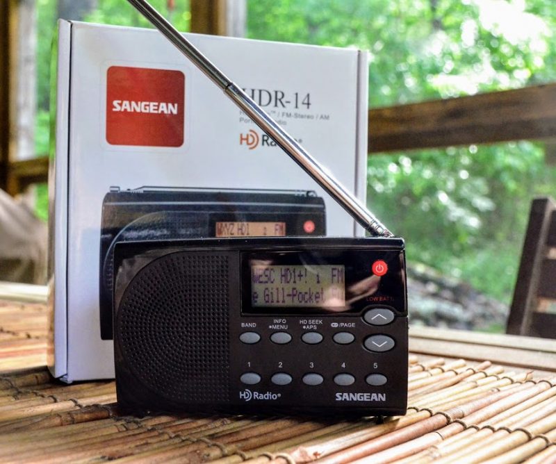
Late last year, we learned that Sangean was planning to introduce a small portable HD radio to their product line: the Sangean HDR-14. Readers were excited about this release––indeed, I’ve received more inquiries and comments from readers about this radio than about any other HD radio.
While there have been numerous portable FM HD radios on the market over the years, there have been very few compact HD portables that can also pull AM HD signals from the ether. Shortly after Sangean made their announcement that the HDR-14 was forthcoming, I contacted them and requested a review unit. They sent me a review sample from the first production run in May.
Due to my exceptionally busy schedule this summer, it’s taken me longer than I’d like to be able to write up a complete review. On the plus side, while I’ve not had a chance to sit down and write, I have had time to listen; thus I’ve had more on-the-air time with the HDR-14, with the result that my review is built on nearly three months of use.
Initial impressions
Size comparison: Sangean HDR-14 (left) and the C. Crane CC Skywave SSB (right)
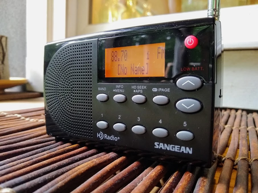
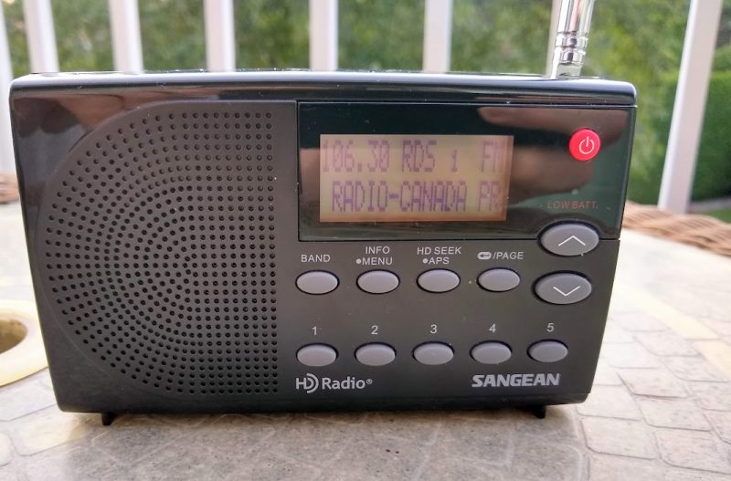
The HDR-14 has a practical AM/FM portable radio design: the front panel features a backlit display, speaker grill, power button, memory preset buttons and a few other buttons to control essential functions like tuning, HD mode/channel selection, band, and information display toggle.
Like most similar Sangean radios, the chassis is a hard gloss plastic finish, while the front panel is mostly matte. The buttons are raised and have a pleasing tactile response.
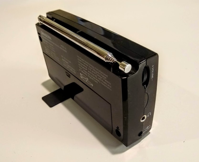
On the left side of the radio you’ll find a coaxial power port (5VDC with a positive tip), volume wheel and headphones jack. I do wish Sangean had used a standard micro USB port, but their alternate choice might be be a result of the fact that USB power supplies are so RF noisy…? This is, however, mere speculation on my part.
On the right side, the only feature is one mechanical key lock switch––a bonus for me, as I prefer mechanical key locks over push buttons.
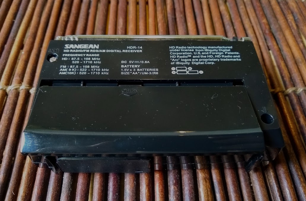
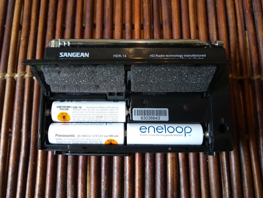
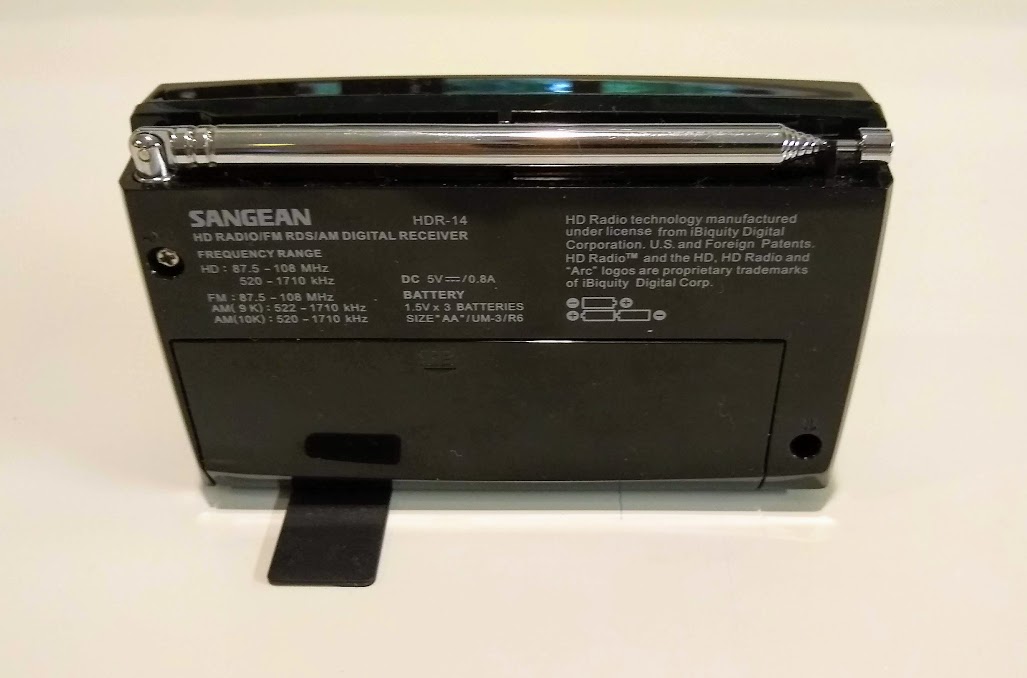
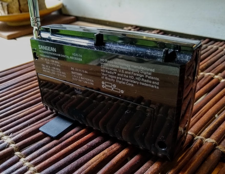
On the back of the radio you’ll find the usual silk-screened product specifications and model information. You’ll also find the large battery compartment cover which easily slides open to reveal positions for three AA cells.
The telescopic antenna is sturdy and about twenty-five inches in length, fantastic for FM radio reception.
One unique feature of the HDR-14 is that it doesn’t have a tilt-out stand on the back, rather a foot that swings out from the bottom/base of the radio. The foot gives the HDR-14 excellent stability while standing up, say, on a night stand next to the bed. Brilliant addition, Sangean!
Features and specifications
For such a compact portable, the HDR-14 sports a compliment of features:
HD Radio digital and analog AM / FM-Stereo reception
40 Memory Presets (20 FM, 20 AM)
PAD (Program Associated Data) Service
Support for Emergency Alerts Function\
Automatic Multicast Re-Configuration
Real Time Clock and Date with Alarm and Sleep Function
2 Alarm Timer by Radio, Buzzer
HWS (Humane Wake System) Buzzer and Radio
Snooze Function
Information Display for Channel Frequency, Call Sign, Radio Text, Audio Mode, Service
Mode, Signal Quality and Clock Time
Easy-to-Read LCD Display with Backlight
Low Battery LED Indicator
I/O Jacks: DC In, Headphone and HD / FM Rod Antenna
The clock and alarm features make the HDR-14 ideal for travel. Sangean’s “Human Wake System” is one of the best wake up alarm systems I’ve ever used on a radio: the buzzer alarm sound will slowly increase in volume for 1 minute, then stop for one minute of silence, and repeat up to one hour. Of course, this will wake most of us on the first go. If not, it’s patiently persistent, but a gentle way to wake: I like this.
The internal speaker is well balanced though it lacks any notes of bass. Still, music is quite pleasing, and the spoken word sounds brilliant and clear. Note that my expectations for audio fidelity are always fairly low from radios in this size class (although the Sangean WR-7 showed me that compact radios are capable of amazing fidelity).
Operation
Tuning the radio and storing frequencies to memory are each straightforward and simple.
Keep in mind, however, that the Sangean HDR-14 can receive both AM and FM radio in analog and HD. On either band, if you tune to an analog station with accompanying HD channels that can be received, the HD Radio logo will flash on the display, indicating that the signal is blending from analog to digital. Once the radio locks onto the HD signal, the HD Radio logo on the display will cease flashing and appear steady.
Saving a station to a memory is simple: 1) tune to a frequency, use the page button to select the desired memory page of five presets; 2) press and hold the button where you would like to store the frequency, and when you hear a beep, the station has been stored. If you chose, for example, the third page and first memory position, “31” (indicating “page 3” and “memory 1,” respectively) will appear on the top line of the display. After entering your presets, you can then recall a station by selecting a page and simply pressing the preset.
The HDR-14 does have a useful “HD Seek” function that searches for HD signals automatically. In addition, there is an HD Auto Preset System that will scan the band for HD signals, then auto-store them in memory presets according to their signal strength. The first memory on the first page will be the strongest station received.
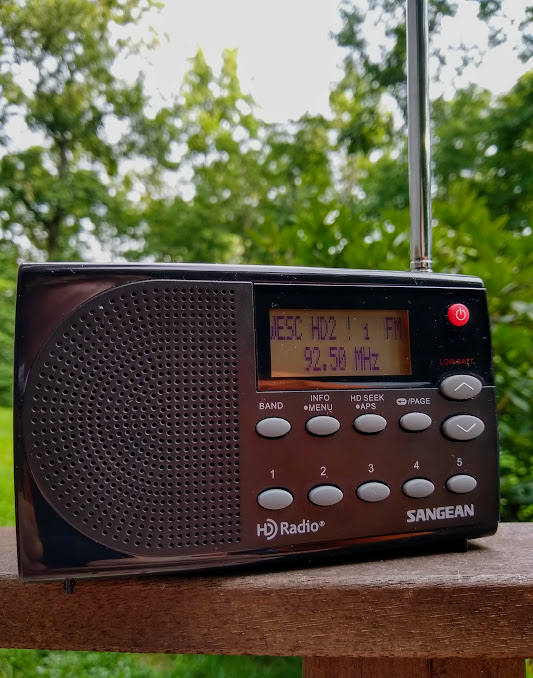
If the HDR-14 acquires an HD station that multicasts (and in my market, most do), the display will note “HD1,” “HD2,” or “HD3,” based on the number of multicast HD signals per broadcaster. You can flip through these with the tune up/down buttons once the display indicates multicast signals.
The HDR-14 also features an alpha-numeric RDS system which makes identifying the station and even their programming/music quite easy. I find that the RDS decode is quite good: it works on even marginal FM signals.
Performance
The last Sangean HD radio I reviewed was the HDR-16, and I was impressed by its performance. As you can imagine, my hope was that the HDR-14 would pack the HDR-16’s performance in a smaller package…So, did it?
Let’s just say it comes quite close.
The HDR-16’s analog AM broadcast band performance is, overall, better than that of the HDR-14. The HDR-14 isn’t poor, but its noise level is slightly higher than the HDR-16’s. I can’t say I’m disappointed with the HDR-14’s analog AM performance, however; it’s just what one would expect. I do wish it had impressed me.
I’ve only received one AM HD signal with the HDR-14, so I can’t comment on the AM HD performance other than to say I was impressed with the steady HD lock. I listened to WWFD in Germantown, MD: I could receive the station both day and even at night when power output was decreased dramatically. I find that AM HD sort of boggles the mind; it’s odd listening to a clear, static-free signal on the AM dial.
I’ve had several SWLing Post readers tell me they were impressed with the HDR-14’s ability to acquire AM HD signals. One reader added that it’s the best he’s ever used…wow! As I travel this year, I hope to snag a few more AM HD signals myself.
The HDR-14 is a very sensitive FM analog receiver. I find that I can receive all of my benchmark local and distant analog FM stations. The HDR-14 seems to be every bit as good as the HDR-16 in terms of sensitivity.
One caveat is that when I tune to an FM analog signal which happens to be adjacent to a strong FM station, sometimes the strong adjacent station bleeds into the audio. FM selectivity isn’t as good as the HDR-16.
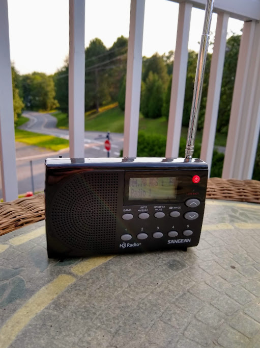
In terms of FM HD performance, you might recall that in my review of the Sangean HDR-16, I mentioned that one of my benchmark distant HD FM stations is WFAE HD2. WFAE’s transmitter is just over one hundred miles from my home shack, and I’m well outside even the the fringe reception area. I’m pleased to note that, on more than one occasion, from my porch, I’ve gotten a reliable HD lock on WFAE with the HDR-14. I’m convinced that when the leaves fall off the trees this fall (they do attenuate signals) reception will be fairly near to reliable.
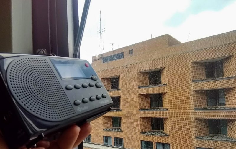
Listening to the HDR-14 from a hospital room.
While waiting for a block of time to pen this review, I’ve spent a lot of time tuning to FM HD signals in a least five different urban and regional markets in two countries. And I can say I’m very impressed with reception; the HDR-14 seems to snag every available HD signal.
Summary
Every radio has its pros and cons. When I begin a review of a radio, I take notes from the very beginning so that I don’t forget some of my initial impressions. Here is the list I formed over the time I’ve spent evaluating the HDR-14.
Pros:
Excellent overall FM Analog and HD performance
Excellent AM HD reception (a stand-out for pocket sized HD receivers)
40 memory presets
Built-in speaker has first-rate fidelity for spoken word and music (see con)
Uses standard AA cells
Excellent build quality
Gentle but persistent alarm
Useful swing out stand for bedside listening and alarm usage
Compact form factor, ideal for travel
Cons:
AM analog performance is acceptable but not for weak-signal work
FM Analog selectivity is mediocre, some strong adjacent station bleed-through
Built-in speaker lacks bass response, so not optimal for all music listening (see pro)
Conclusion
While I have mixed feelings about digital radio in general––but especially In-band on-channel (IBOC) HD radio––I do love exploring all that over-the-air radio has to offer. Like it or not, HD radio is a part of that landscape for the foreseeable future.
HD Radio has opened up a few alternative music stations that otherwise I’d never have discovered in my local market. In addition, I find that NPR and public radio stations often multicast commercial-free talk, jazz, and classical music, which makes HD Radio a worthy addition at home and while I travel. In large urban markets, HD Radio certainly increases the number of available commercial options sometimes by a factor of two or possibly more.
If you like chasing AM and FM HD signals, you’ll be very pleased with the HDR-14. It’s first rate, and I recommend it.
The Sangean HDR-14 RDS display (Photo: Thomas)
I’ll close by adding that I continue to be impressed with Sangean as a company. They’ve always been one of the quality leaders in the portable radio marketplace, and still make products with the radio enthusiast in mind––something of a rarity these days. I always look forward to seeing what they’ll come up with next!
The Sangean HDR-14 can be purchased at a number of retailers including:
Many thanks to SWLing Post contributor, Gary DeBock, who shares the following notes and recordings from the latest Rockwork DXpedition.
Top Ten DU signals from the August 2018 Rockwork DXpedition
– Gary DeBock
Life is good– breathtaking ocean scenery, an innovative compact antenna, thunderous DU signals and even a partner (Craig Barnes) to share in the bounty. Who could ask for more?
Listed below are the Top Ten DU signals recorded during the recent Rockwork ocean cliff trip (near Manzanita, Oregon) from August 1-9, including several low-powered Kiwi stations which acted like “big guns” pretty much throughout the DXpedition. All of these were recorded with 7.5″ loopstick portables (CC Skywave SSB and XHDATA D-808) and “Airport Unfriendly” 15″ and 17″ FSL antennas (guaranteed to send TSA agents into a security alert).
531 More FM Alexandra, New Zealand, 2 kW The obscure modern rock station usually managed at least one S9 peak each morning, and was fully competitive with Kiwi co-channel PI for the first time. This TOH recording at 1300 on 8-8 demonstrates its potent capability at the cliff
531 PI Auckland, New Zealand, 5 kW Pacific island music at a huge level at 1248 on 8-7 was typical from this low band powerhouse, which was frequently in an all-Kiwi snarl with its overachieving co-channel More FM
558 Radio Fiji One Suva, Fiji, 10 kW The donated Japanese transmitter still puts out awesome signals for this native-language powerhouse, including this island music with a Song Medley ID (“Radio Fiji One, na domoiviti”) at 1:38 into this recording at 1252 on 8-1
567 RNZ National Wellington, New Zealand, 50 kW After demolition of its old tower the RNZ big gun has sometimes sounded anemic on the west coast, but certainly not at 1320 on 8-3 with Indian-accented English
585 7RN Hobart, Tasmania, Australia 10 kW The RN network Tasmanian must have somehow hacked into the Kiwi propagation pipeline at 1306 on 8-6; at the time it was much stronger than its 576 parallel
594 Star Timaru/ Wanganui, New Zealand 5 kW/ 2 kW Another Kiwi overachiever, this low powered network was socking it to the Oz big gun 3WV all week, including with this powerful Christian music // 657 at 1326 on 8-3
657 Star Wellington, Tauranga, New Zealand 50 kW/ 10 kW The flagship Star station sure was playing the part with Christian music at an overwhelming level at 1238 on 8-6, including an ID at the end of the recording
765 Radio Kahungunu Napier-Hastings, New Zealand 2.5 kW The overachieving Maori station was its usual potent self with island music and Maori chants at 1218 on 8-1; it was usually slightly stronger than its 603 parallel (Waatea)
936 Chinese Voice Auckland, New Zealand 1 kW One of the most incredible signals of the entire DXpedition– the 1 kW ethnic station pounds into the cliff at an S9 level at 1309 on 8-2– ocean cliff propagation at its finest!
1017 A3Z Nuku’alofa, Tonga 10 kW Yikes! The rejuvenated Pacific island big gun thunders into the cliff with the strongest signal I’ve ever heard recorded in North America, featuring island music at 1314 on 8-1… almost loud enough to wake up the sleeping squatters
Gary DeBock (DXing at the Rockwork ocean cliff near Manzanita, Oregon, USA with Craig Barnes from August 1-9)
Thank you for sharing those catches, Gary! It’s amazing what DX you can snag with an ultralight radio and a homebrew FSL loop antenna. Someday, I hope to join you guys on the cliff!
Many thanks to SWLing Post contributor, Laurence Neils, who shares the following guest post:
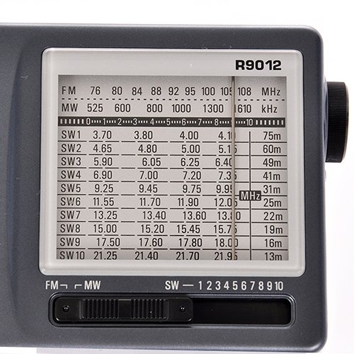
A review of the Tecsun R-9012
by Laurence Neils
I have cheap radios. I can’t really justify buying more expensive ones given how much time (not all that much) I spend listening to the short wave broadcasters. The consequence of this is that, when I do listen to shortwave stations, I have the rather standard ultraportables to listen on.
My go-to radio is the Tivdio V-115, which has pulled out quite nice reception for me, and offers several functions I like a lot. However, it was missing one that interested me the most: analog or analog-like tuning. If I want to listen to something, I either have to know its frequency and try it, or I have to let the radio do an automatic scan. While it’s quite good at pulling out stations and letting me hear them, it can take a few minutes to do a full scan, and canceling it doesn’t result in the part scanned so far to be stored. Very few stations I am interested in hearing are convenient to jump into several minutes after they start (my interest is in spoken content rather than music, and neither news nor stories make a ton of sense if the introductory information was not heard).
From a recommendation here on the SWLing Post, I chose to purchase a Tecsun R-9012 radio to help me do a convenient scan, which is useful because it allows me to find stations without knowing their frequency, and leaves me to not remember all seventy frequencies a certain broadcaster is using this year.
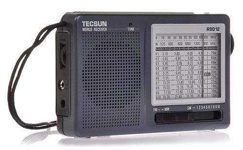
Physical Description
When I bought my Tecsun R9012, it arrived quite quickly from Amazon. It included a short manual, whose contents could be loosely paraphrased as “insert batteries and turn on”. Other than that, the radio is all that’s there.
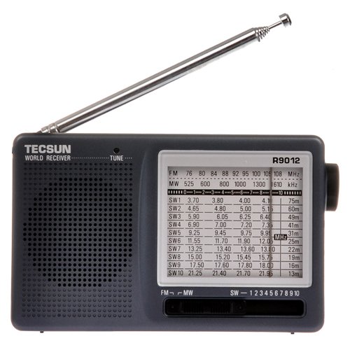
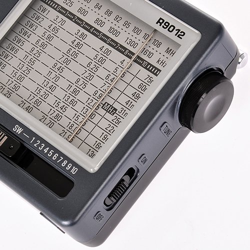
The R9012 is relatively small, but not as thin or compact as the Tivdio, which will be my main comparison unit for this review. It is your basic rectangle form factor, and about the size of the small tape recorders that were the last to be phased out for portable recorders. It would be easy enough to put this in a backpack, jacket pocket, or glove compartment, but you have no chance comfortably fitting it into a standard pocket. On the back, there is a flip-out kickstand that can hold the radio at about thirty degrees from horizontal and the battery compartment. This radio is powered from two AA batteries.
The right side of the R9012 contains the analog tuning knob, which I will discuss quite a bit later, and the power switch, which is not connected to anything else (not integrated into the volume knob or mode selector).
The left side gives you a 3.5mm audio out jack. This supports all the headphone types I’ve tried. One benefit of this radio is that headphones with integrated microphones, such as the ones that come with the iPhone as well as various sets that are intended for phone use, will work with it. Some other radios won’t work well with that type of headset. The Tivdio, for example, will play through the headphones but forgets to turn off the speaker if there is a microphone on them, making the headphones pretty much pointless.
Next to that jack is a power port, supposedly to recharge the batteries. A connector for this is not included, nor do they seem to sell one. I suppose the theory is that you might already have a suitable one in that box of old cables we all have, but I can’t see this as a particularly useful feature given the RFI you’ll get if you connect a radio directly to the mains to recharge. Above the ports is the volume knob, which is a very basic analog one, and then the wrist strap, which is integrated into the case. There doesn’t seem to be a way to remove or change it, should you desire that.
On the front of the radio, the speaker takes up the left half. This is fine for standard listening, but don’t expect wonders of audio fidelity. On the right half, there is the twelve-position mode switch (from left to right, FM, MW, SW from low to high frequency) and the tuning display.
FM performance
The Tecsun has a standard FM function, with stated coverage from 76 to 108 MHz. This is the leftmost position on the mode selector. The band is not divided into multiple switch positions, meaning that stations will be relatively packed into dialing space when compared to shortwave, which is spread across ten bands.
I didn’t buy this radio to use it for FM. I have very little interest tuning for FM stations. Some people may enjoy the experience of manual tuning for a station they can locate quickly, but I’m not one. I can easily type the frequency I want on my Tivdio, and I intend to keep doing that for FM. I mostly intended to test FM performance on the R9012 because I was curious to see whether there would be anything audible in the 76-87 MHz section. I know that our TV standards have switched off using analog audio, so I assumed there would be nothing, but I’d never formally put that to the test.
FM on the R9012 has problems. In fact, it has a lot of problems. Among other things, the FM process on this radio doesn’t seem to have a very good idea where things are. I’d be tuning through looking for some station and I’d find it…only to see that I was in a completely foreign part of the spectrum where that station had no business being. It seems that, unless you’re very focused in on a station, the R9012 is liable to pick up some other broadcast and layer them on top of each other. Never mind that the broadcasts have nothing to do with each other and aren’t anywhere near each other on the band. If you have a specific station you want, you can tune to it and have no problems. If you want to see what’s there, you’ll have a very fun time listening to stations that you might want to listen to, only to find that that was an image, you’ve lost it now, and you can’t find it again.
Sometimes, I managed to find a part of the spectrum that gave me three different images simultaneously. Ironically, the broadcast I intended to use as my landmark, the local classical music broadcast, which is located very close to the middle of the FM spectrum, was strong enough or at a coincidental frequency that I identified images of it at six different places on the scan, in addition to where it should be. So I got my answer about 76-87 MHZ. According to the R9012, there’s a lot of signal there. It’s just coincidence that it sounds exactly the same as standard FM broadcasts with extra static.
FM performance gets worse: this radio is extremely sensitive to location.
In order to get nice reception, you have to have the radio in a good position. This seems to be completely random. Standing up so the antenna lies flat on the top, but is not extended produces almost silence. Lying down so the antenna is touching the table (not a metal table) or chair (not a metal chair) causes most signals and images to come through quite clearly. Extending the antenna to medium length helps reception. Extending it all the way introduces a lot of interference. On FM, volume also changes a lot. We may reasonably expect for the signal to change if we connect something conductive to the antenna by, say, touching it with our conductive fingers. Maybe reception will get more static, or maybe it will in fact improve. What we don’t expect is for the broadcast to switch from comfortable volume to let’s see if we can get you some tinnitus volume. Unfortunately, that’s sometimes what happens on FM if you touch the R9012’s antenna. Or tilt it a bit in the wrong direction. This doesn’t seem to happen much if it is tuned onto a station, but if it is anywhere in the middle or if there’s some static, the volume change is very noticeable, in that it makes you want to get the radio off as soon as possible.
In summary, this radio just can’t really do FM. If your other radios are broken, you’ll be fine by using this, but don’t buy it if you intend to do FM things.
Mediumwave performance
The MW frequencies are mostly there, with stated specs including from 525 to 1610 kHz. While there are broadcasts between 1610 and 1710 KHZ, that’s not a ton of the spectrum. I don’t have much interest in MW. I tested the radio’s performance, and it seems fine. Strong stations come in loud and clear. Stations that have low broadcast powers are easy to tune in. I was able to get some skywave MW in here as well, but I really don’t have any interest in that. I was able to verify, however, that the terrible effects that plague FM performance don’t appear on MW. I got no images of distant stations, no rapid volume switches, and the position of the radio doesn’t seem to affect MW reception all that much. Perhaps this is due to the different antenna that most radios employ in tuning MW. However, the manual doesn’t say whether this radio has such an alternative antenna and I haven’t gone to the effort of disassembling it to find out.
Shortwave performance
Once again, the crazy stuff seen on the FM band doesn’t appear during shortwave listening. I was able to tune in quite a few stations, although this probably isn’t a DX-capable device unless you’re willing to go out into RFI-free areas. That sounds enjoyable, but it’s not really my thing. When I got signal, it came in quite clearly. I got very little interference from the device itself, although it does seem quite susceptible to RFI from power lines. Of course, so is everything else, but if you put its antenna closer to a line, you’d know it.
Frequency coverage
Shortwave is covered in ten bands that allow access to the more populated areas of the spectrum, but have many gaps. Certain descriptions claim that the radio has coverage from 3.90 to 21.85 MHz. This is so misleading I’d be willing to call it a lie. The actual ranges are as follows:
SW1: 3.7 – 4.10Mhz
SW2: 4.75 – 5.06Mhz
SW3: 5.95 – 6.20Mhz
SW4: 7.10 – 7.30Mhz
SW5: 9.50 – 9.90Mhz
SW6: 11.65 – 12.05Mhz
SW7: 13.60 – 13.80Mhz
SW8: 15.10 – 15.60Mhz
SW9: 17.55 – 17.90Mhz
SW10: 21.45 – 21.85Mhz
So what if most signals are in there somewhere? Those gaps are very large. For example, the only broadcast frequency for WWV that would be covered on this set is the 5MHZ one. 10, 15, and 20MHZ are all located in various gaps on the bands.
This turned out to be quite annoying. I know that these are standard areas of the spectrum, in which people place a preponderance of broadcasts, but the fact remains that a lot of broadcasts occur between the bands on this set. I checked the A18 shortwave schedule to identify how crazy I was. Of the 5530 broadcasts that were listed between the limits of 3.90 to 21.85 MHZ, 1870 of them or 33.8% of the total, are outside the range of this set.
It strikes me that the largest band on this radio covers only 500 kHz of space, whereas the smallest gap between bands covers 750 kHz. In many cases, bands cover only 100 kHz of bandwidth. While I guess it’s better that they’re there rather than their being completely absent, perhaps some effort could have been done to open that up a bit more. I quickly analyzed where missing signals were, and if Tecsun could extend the 5.95-6.20 MHz band down to 5.8 MHz, 7.10-7.30 up to 7.60 MHz, expand the 9.5-9.9 band, and give an extra 50 kHz to the 11.65-12.05 band, most of the missing spectrum, nearly a thousand broadcasts, would be brought back into coverage. This could be done and still keep the maximum band width at 500 kHz. Therefore, as they didn’t seem to feel this an important issue, it falls to me to consider it so.
Manual tuning
So I bought this to tune manually. It stands to reason that I should review how well it does that.
The analog dial is on the right, and protrudes outward. Once again, the knob does its job, but not all that well. It was very easy to use this to pan through the spectrum and pick up stations, but the wheel doesn’t make it all that easy to do so quickly. You have to turn it by grasping, as the wheel has a fair bit of resistance. I don’t doubt that this feature helps to keep from knocking it off frequency, but you have to use two fingers to rotate freely, and that slows the process down. Meanwhile, the wheel has a rather disconcerting way of stopping, where the wheel seems to have hit an obstruction. However, this essentially increases the resistance, rather than feeling like a barrier. It’s noticeable, but it feels like something’s blocking the turning mechanism, rather than that the mechanism has reached its limit. Actually, it is possible to keep turning the dial, which I assume will eventually damage something, but if you’re not used to how it feels, you may do so without realizing that you’re not actually going anywhere.
The wheel has quite a bit of travel. On my set, it will rotate about three full turns. I believe this is necessary because all of FM, including the standard and Japanese bands, is in one section. Therefore, the wheel needs to be able to turn a lot in order to separate those stations. However, this means that panning over a shortwave band that covers at most 500 kHz of spectrum includes a great deal of panning over static. This works to scan quickly, but there are undoubtedly even faster ways to do so.
Conclusions
It’s a radio. It will pick up stations and make noise. In that, it works. However, this isn’t exactly a great set. The $22 price tag may forgive some of its flaws but not all of them.
Radios like the Tivdio models cost similar amounts and cover the spectrum more fully with some extra features. When I purchased this model, I expected the lack of features to be made up by convenient scanning over shortwave, relatively good sound, and relative disposability. I got enough for me to keep the set, but nothing more.
Pros:
Mediumwave is rather sensitive for those who enjoy listening to those signals.
Radio has a kickstand and the antenna can be rotated freely.
Radio supports headphones with inline microphone.
Cons:
FM is plagued by images of other stations that should not be there. This is rather bad.
FM is far too sensitive to antenna position.
Shortwave coverage, while it includes most of the spectrum in use, has big gaps that are actually being used by a lot of broadcasters.
Analog tuning works, but not really well. The knob can turn but does so with effort.
Would I recommend people to purchase this? Probably not.
Those who have higher-priced devices will get nothing from this. Those getting into the hobby aren’t going to get a ton of benefit from this, because tuning on shortwave requires enough familiarity with dial position that they may spend too long figuring it out. It would be useful on FM only if most other radios have been broken. It’s not even that good as an emergency set because of the FM sensitivity problem.
If all you want is analog tuning over the bands that are provided, the radio will do it for you. If you want more, buy something else.
Thanks for sharing your evaluation Laurence. Thanks for focusing on one of the points that is often overlooked with analog radios: the frequency coverage on various shortwave bands. The R-9012 does seem particularly segmented.
The proposed sale of an AM station along the Mexico-U.S. border to a group of Chinese investors has stoked fears that the 50,000-watt station will be used to infiltrate the U.S. with Chinese propaganda. Spanish news-talk “W-Radio 690” XEWW (690), which blankets Southern California from Tijuana, is being sold by Mexican broadcaster GLR to Chinese investment group H&H Group USA, owned by Vivian Huo, a U.S. citizen who runs the investment firm H&H Capital Partners.[…]