Shortwave listening and everything radio including reviews, broadcasting, ham radio, field operation, DXing, maker kits, travel, emergency gear, events, and more
Many thanks to SWLing Post contributor, Franco (K4VZ) , who writes:
Just a quick note to let you and the SWLing post readers know about the news of a backdoor in the KiwiSDR software that for years “gave root to project developer”.
For years, a backdoor in popular KiwiSDR product gave root to project developer
Users are rattled after learning their devices and networks were exposed.
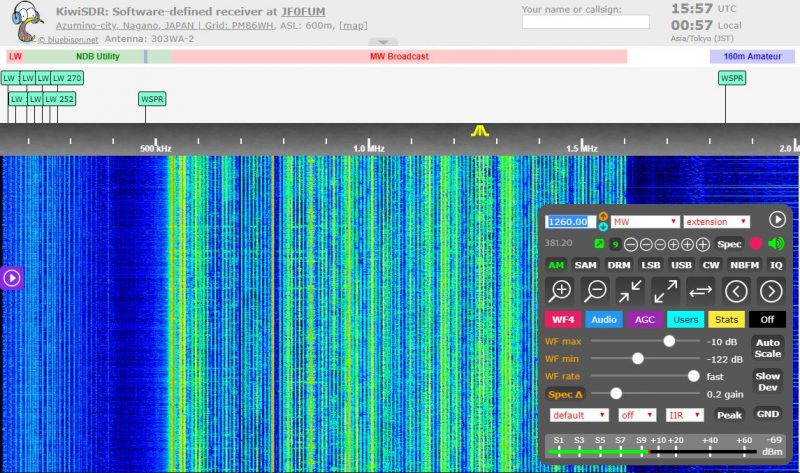
KiwiSDR is hardware that uses a software-defined radio to monitor transmissions in a local area and stream them over the Internet. A largely hobbyist base of users does all kinds of cool things with the playing-card-sized devices. For instance, a user in Manhattan could connect one to the Internet so that people in Madrid, Spain, or Sydney, Australia, could listen to AM radio broadcasts, CB radio conversations, or even watch lightning storms in Manhattan.
On Wednesday, users learned that for years, their devices had been equipped with a backdoor that allowed the KiwiSDR creator—and possibly others—to log in to the devices with administrative system rights. The remote admin could then make configuration changes and access data not just for the KiwiSDR but in many cases to the Raspberry Pi, BeagleBone Black, or other computing devices the SDR hardware is connected to.
A big trust problem
Signs of the backdoor in the KiwiSDR date back to at least 2017. The backdoor was recently removed with no mention of the removal under unclear circumstances. But despite the removal, users remain rattled since the devices run as root on whatever computing device they’re connected to and can often access other devices on the same network.
“It’s a big trust problem,” a user with the handle xssfox told me. “I was completely unaware that there was a backdoor, and it’s hugely disappointing to see the developer adding backdoors in and actively using them without consent.” [Click here to continue reading the full article…]
Thank you for sharing this, Franco (and many other readers who’ve recently shared this article.
I’ve always been a big fan of the KiwiSDR network and the receiver so, of course, this is disappointing news. It sounds as if there’s no evidence the developer did anything nefarious through this root access backdoor, but they were also well aware it existed. That is, without question, a huge security issue.
The KiwiSDR developer comments here on the SWLing Post so my hope is that, perhaps, they can shed some light on this story in our comments section.
Many thanks to Jon Hudson with SDRplay who shares the following announcement:
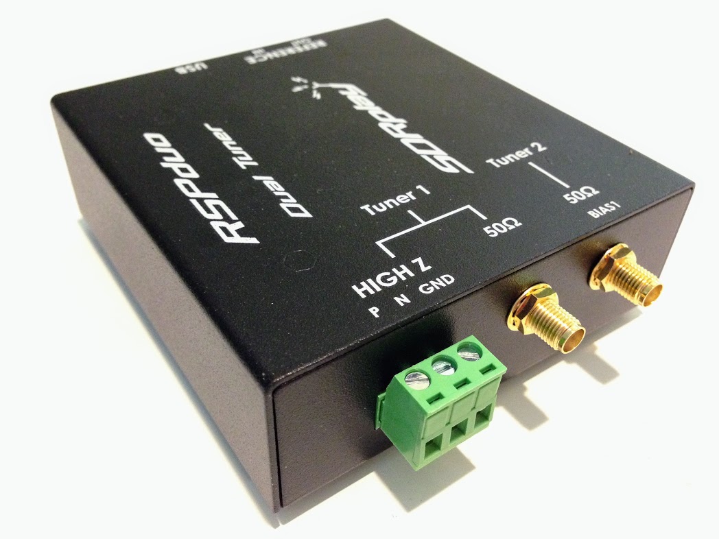
Introducing a new series of videos comparing the performance of wideband active loop amplifier/antennas for HF frequencies and below. In this introductory video, Mike Harwood shows how an RSPduo enables a real-time comparison of two antennas – in this demo, he uses a Wellbrook 1530AN and one of his own compact loop creations. You can see that he has lined up several other active loop antennas/amplifiers to try in future videos, including the Bonito Megaloop FX, the LZ1AQ amp and the Cross Country Wireless amp.
This is one of many videos from SDRplay – makers of the RSP family of SDR radios. See the full list of SDRplay videos and applications documents on: https://www.sdrplay.com/apps-catalogue/
The RSP family of SDRs from SDRplay cover 1kHz to 2 GHz with no gaps and give up to 10MHz spectrum visibility.
SDRplay is a UK company. The RSP SDR receivers are made in the UK and can be purchased for worldwide delivery directly from http://www.sdrplay.com/ (click on purchase and select your country to view shipping costs) or you can buy from any of our worldwide resellers listed here: http://www.sdrplay.com/distributors/ Many of the resellers offer local free shipping and/or local language technical support.
Many thanks to SWLing Post contributor, TomL, who shares the following guest post:
Recording Music on Shortwave Part 2 – Weak signal recovery
by TomL
The QRM noise cloud surrounding my condominium motivated my first foray into noise reduction software to find a little relief (Please refer to Part 1 posted here) using SDR recordings. I was able to use the freeware software Audacity to reduce some of that type of noise to tolerable levels on strong broadcasts. But what about non-condo noise, like out in the field??
NHK Japan
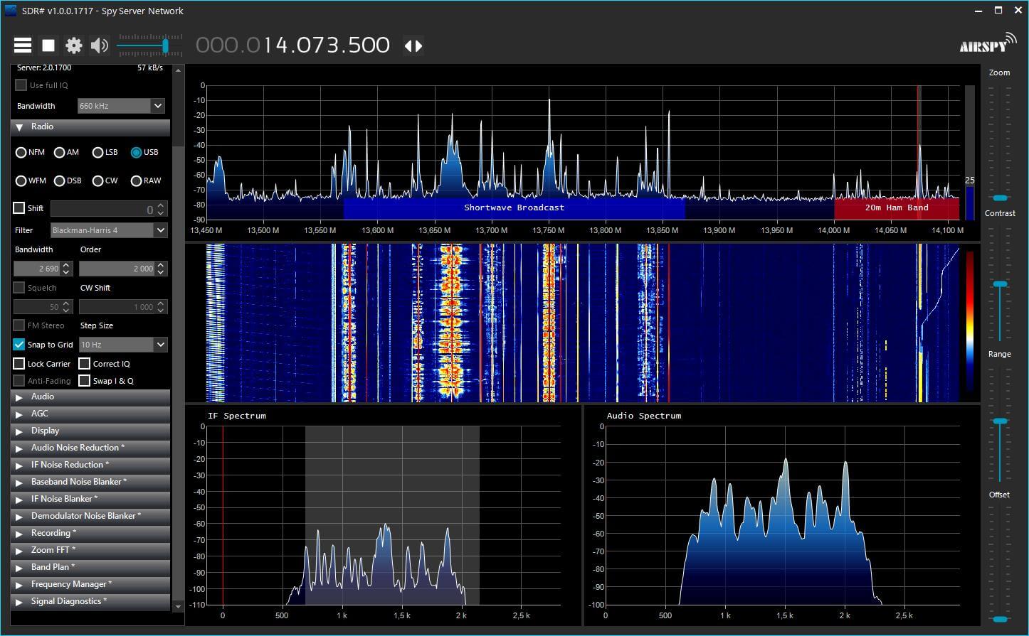
I took my trusty Loop On Ground antenna to the usual county park Forest Preserve which is relatively low in RF noise. I did some usual recording on 25 meters and poked around for something being captured by SDR Console. On 11910 kHz is NHK broadcasting daily from Koga, Japan. It is hearable at this location but is always an S7 or weaker signal despite its 300 KW of power no doubt due to being beamed away from the Midwest USA.
I recorded it using the SDR Console 10kHz bandwidth filter and created a separate noise recording from a nearby empty frequency. Here is the 2 minute portion of a Japanese music teacher. No noise reduction was applied:
I opened the noise and broadcast recordings in Audacity to see what I could do. Part 1 of my previously mentioned post details how I apply the Noise file. A big downside of using any kind of noise reduction software is that it is ridiculously easy to destroy the desirable characteristics of the original recording. Applying too much noise reduction, especially in the presence of constant, spiky lightning noises, will create both digital artifacts as well as very dull sounding results. So I used the Effect – Noise Reduction (NR) feature very carefully.
In this example, I used the Effect – Amplify feature on the one minute noise file. I applied just +1dB of Amplify to the whole file. Then I highlighted a 10 second section I thought was representative of the general background noise and chose Edit – Copy. Then, I opened the broadcast file, Pasted the 10 seconds of noise to the END of the file and highlighted just the 10 seconds of noise. Then I chose Effect – Noise Reduction – Get Noise Profile button. Amplifying the noise file by +1db does not sound like much but it seems to help according to my tests. Anymore than this and the Noise Profile would not recognize the noise without destroying the music.
I used the NR feature three times in succession using the following (NoiseReduction/Sensitivity/FrequencySmoothing) settings: Pass1 (3dB/0.79/1), Pass2 (2dB/1.28/1), Pass3 (1dB/2.05/0). Part of what I listened for was choosing the Residue circle and Preview button for any music or dialog that was being filtered out. If I heard something that came from the desired part of the recording in Residue, I knew that I hit the limit concerning the combination of Noise reduction and Sensitivity settings to engage. I used those Residue & Preview buttons over and over again with different settings to make sure I wasn’t getting rid of anything wanted. I also used the higher Noise reduction with lower Sensitivity to try to get rid of any momentary spiky type noise that is often associated with SWLing.
I messed around with a lot of test outputs of differing dB and Sensitivities and a lot seemed to depend on the strength of the broadcast signal compared to the noise. If the broadcast was weak, I could push the dB and Sensitivities a little harder. I also noted that with strong signal broadcasts, I could NOT use more than 1 dB of Noise reduction beyond a Sensitivity of about 0.85 without causing damage to the musical fidelity. This was a pretty low level of nuanced manipulation. Because of these minor level Audacity software settings, it dawned on me that it is very helpful to already be using a low-noise antenna design.
If the Sensitivity numbers look familiar, that is because I tried basing the series of Sensitivity on Fibonacci numbers 0.618 and 0.786. Don’t ask me why these type of numbers, they just ended up sounding better to me. I also needed a structured approach compared to just using random numbers! Probably any other similarly spaced Sensitivity numbers would work just fine, too.
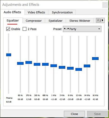
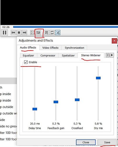
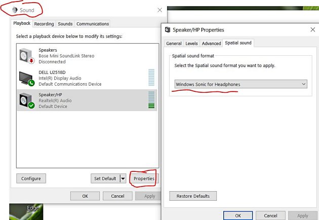
Now if you really want to go crazy with this, add Pseudo Stereo to your favorite version of this file (also detailed in Part 1) and playback the file using VLC Media Player. That software has a couple of interesting features such as an Equalizer and a Stereo Widener. You may or may not like using these features but sometimes it helps with intelligibility of the voice and/or music [VLC will also let you right-click a folder of music and choose to play all it finds there without having to import each MP3 file into a special “Library” of music tracks where they bombard you with advertisements].
You can also turn on Windows Sonic for Headphones if you are using the Windows operating system. However, this can sometimes be too much audio manipulation for my tastes!
Here is the resulting NHK noise-reduced file with 9ms of delay with High & Low Filters:
Radio Thailand
Five days later I was out in the field again. This time I found Radio Thailand on 11920 kHz finishing up a Thai broadcast. It was a weaker S5 signal than the NHK example, so it would be a good test.
When I got home, I recorded the broadcast file at a Bandwidth filter of 8 kHz and using Slow AGC and the extra Noise file at 12kHz using Fast AGC. In a previous test I had noticed a very slight improvement in sound quality in the way noise seems to get out of the way quicker compared to Slow AGC (which is usually how I listen to shortwave broadcasters). I now try to remember to record the Noise file with Fast AGC.
Here is the original without any noise reduction:
This time the Noise file using Amplify +1dB did not help and I used it as-is for the 10 second Noise Profile. I then tried multiple passes of NR at higher and higher Sensitivities and ended up with these settings the best: Pass1 (1dB/0.79/0), Pass2 (1dB/1.27/0), Pass3 (1dB/2.05/0), Pass4 (1dB/3.33/0).
As a comparison, I tried recording only with SDR Console’s noise reduction NR1 set to 3dB and got this. I hear more noise and less of the music coming through:
Now for more crazy Pseudo Stereo to finish up the Audacity 4Pass version (nice Interval Signal of Buddhist bells ringing and station ID at the very end):
Summary
I do not understand why applying 3 or 4 separate 1dB Sensitivities of noise reduction is superior to just one Pass at 3dB Sensitivity (in Audacity) or the one 3dB noise reduction (in SDR Console). My guess is that doing 1 dB at different Sensitivities shaves off some spiky noise a little at a time, somehow allowing for more of the musical notes to poke through the noise cloud. Who knows but I can hear a difference in subtle musical notes and sharpness of voice and instruments. Probably the Fast AGC helps too.
Music is a Universal Language that we can share even when we don’t understand a word they are saying. And there is more music on the air than I thought. Some of these recordings sound surprisingly pleasing after noise reduction. The fake stereo is pumped through a CCrane FM Transmitter to a few radios in the home, or I can use the Beyerdynamic DT990 Pro headphones.
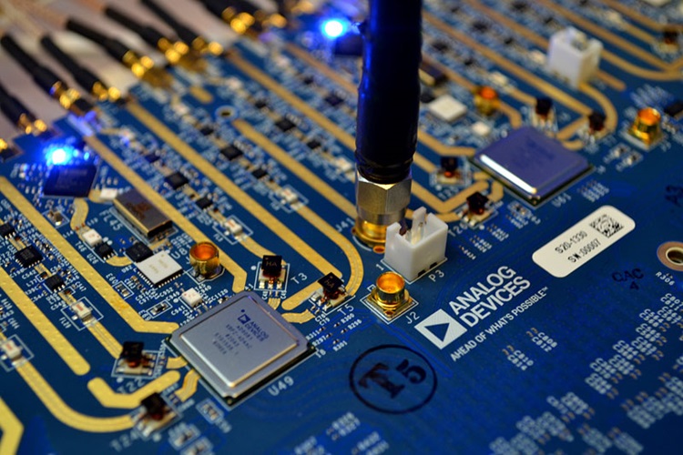
Many thanks to SWLing Post contributor, Paul Evans, who shares info about the new Analog Devices MxFE and notes that it could be a game changer in the world of software defined radio:
This does sound like a very robust and powerful platform although I’m not an engineer so can’t speak to how it might be integrated in affordable SDR receivers and transceivers..
Many thanks to SWLing Post contributor, 13dka, who shares the following guest post:
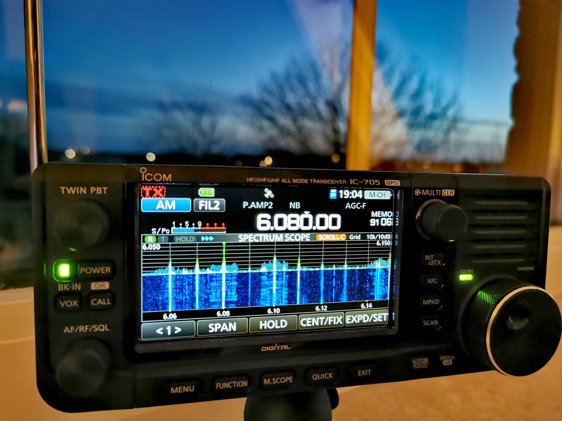
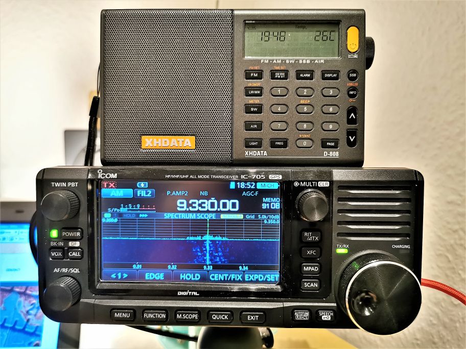
The Icom IC-705: Is this really a new holy grail SWL/BCL receiver?
by 13dka
When Thomas got wind of its development in 2019 he immediately asked “could the Icom IC-705 be a shortwave listeners holy grail receiver?”. I usually wince a little when I hear “holy grail” because it means very different things to different people, it’s also a moving target with many people aiming at the spot where it was decades ago. But Thomas certainly had a very level-headed assembly of technical performance, quality and practicality requirements in mind when he used that term, and I thought he might be onto something!
There are some excellent, trustworthy reviews of the IC-705 out there. The following is not one of them, I just want to share an opinionated breakdown on why I think this is an interesting radio for SWLs/BCLs indeed, also deliberately ignoring that it’s actually a transceiver.
Jumping shop
While the era of superhet/DSP-supported tabletop holy grails ended with the discontinuation and sell-off of the last survivors more than a decade ago, powerful PC-based SDR black boxes were taking over the mid-range segment and it became very slim pickings for standalone SWL receivers: Thomas just recently summed up the remaining options here.
Between the steady supply of inexpensive yet serviceable Chinese portables, upgraded with a least-cost version of DSP technology, and the remnants of the high end sector there’s very little left to put on the wish list for Santa – that doesn’t need to be paired with a computer that is.
No surprise that SWLs/BCLs in search of new quality toys with tangible controls are taking a squint over the fence to the ham transceiver market: Hams are still being served the best and the latest in radio technology in all shapes and sizes, and even entry-level rigs usually come with feature-rich general coverage receivers. But transceivers never had SWLs much in their focus in the past decades, and particularly not BCLs: Frontend adaptation, additional AM filters, switches and functions would’ve meant increasing costs and so transceivers were never perfected for that purpose. DSP and SDR technology allowed for improvements on that without actually adding (much) hardware and so some interesting alternatives surfaced in the past years, but most of them still come with little downers, at least for BCLs.
Many thanks to SWLing Post contributor, John K5MO, who writes:
Hi Thomas
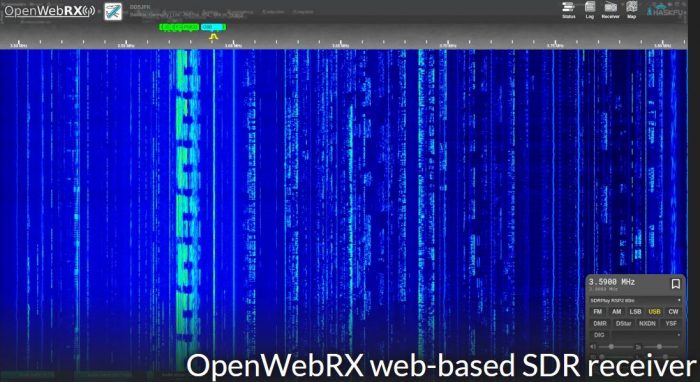
Just a heads up if you didn’t know…openwebrx has a new release and it’s a good one. No more muddling around with a text editor to change configurations, rather there’s a built in editor for this purpose. The release is V1.0 and it can be found

 Many thanks to SWLing Post contributor, Franco (K4VZ) , who writes: