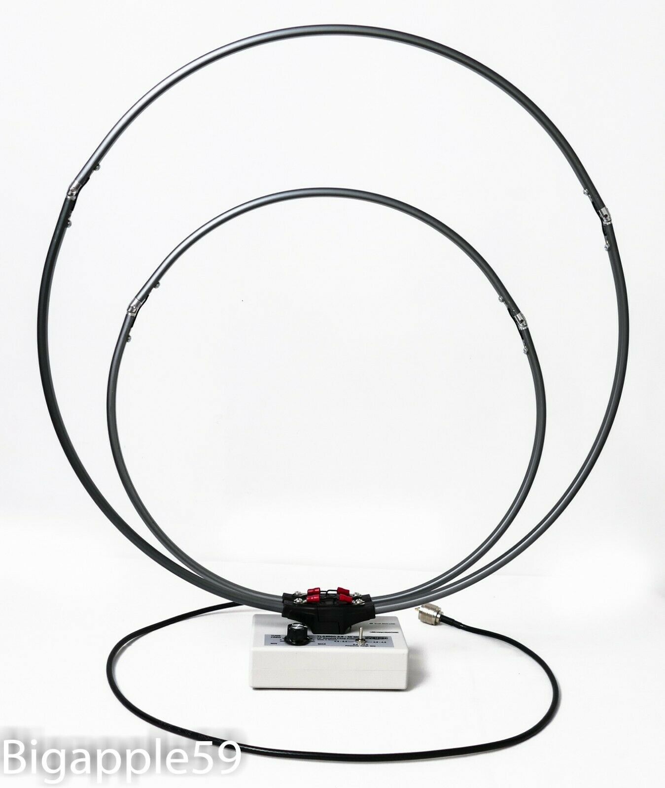
Many thanks to SWLing Post contributor, Ola, who shares a link to this inexpensive mag loop antenna on eBay.
I have no clue if this antenna performs as well at all, but the price is certainly much lower than its competition at $47.99 US.
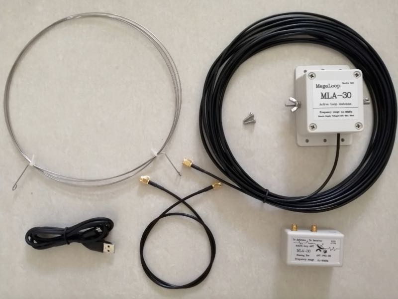
It appears you’ll need to supply your own dielectric center support for this loop–a length of PVC would do the trick.
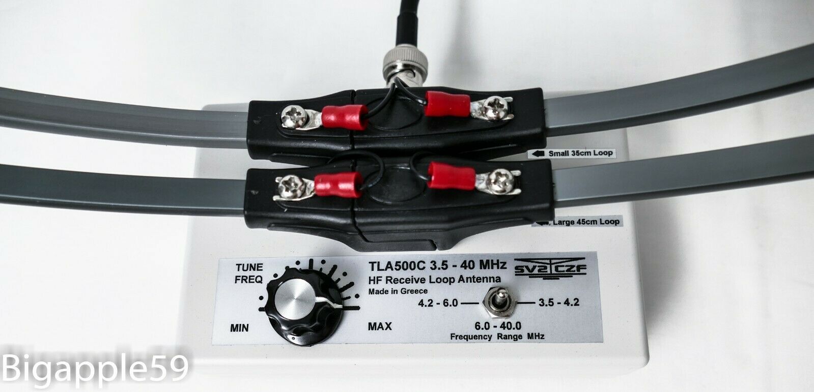
Copycat–?
I don’t like the fact this manufacturer has chosen the name “Mega Loop Active” for their antenna as the name is too similar to Bonito’s “MegaLoop FX Active.” I don’t like the confusion that could create, so I would hope this Chinese manufacturer would change this in time.
To be very clear, this product has no affiliation with Bonito and I certainly would not expect the quality or performance you would get from a Bonito product. Bonito products are pricey, but they’re design and manufactured in Germany and set benchmarks in terms of performance and quality. I’m a big believer in “you pay for what you get.”
I suppose though if you’re just looking for a cheap antenna to test, this one is quite inexpensive. Just know that it is not a Bonito MegaLoop, despite the similarities in product name! 🙂