This article originally appeared in the November 2015 issue of The Spectrum Monitor magazine:
Despite the often-expressed view that shortwave may be on the decline, if one were to look at this year’s shortwave technology alone, the truth would seem to be anything but. Remarkably, 2015 has been a great year for the shortwave radio listener, as several models of portables, tabletops, and SDRs have been either introduced or improved.
The following is a basic, easy-to-follow buyer’s guide to some of the best receivers on the market currently. This guide is, by no means, comprehensive; rather, it’s a selection of rigs I have tested, some of which I now own. It builds on the guide I published in the November 2014 issue of TSM, and highlights innovations since that issue, while still acknowledging the contributions of previous models.
Compact/Travel portables
If your budget is tight, or if you’re looking for a radio that could easily slip into your glove compartment, backpack, carry-on, or even jacket pocket, you need to consider a compact shortwave radio.
Typically, there is a performance compromise with compact radios: they don’t always have the sensitivity of their more expensive cousins; they have a more limited frequency range; and they don’t detect single-sideband signals. Nonetheless, the ones listed here are fine performers for their size and price. Entries are listed in alphabetical order.
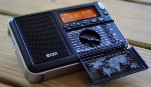
The Eton Traveller III
Eton Traveller III
Eton has once again refreshed the design of its popular “Traveller” series of compact receivers: their latest is the third edition, the Eton Traveller III. I’ve owned the past two versions of the Traveller, and having learned to appreciate these, was eager to get my hands on the newest Traveller III. As the name implies, this is a great little radio for the international traveler; it not only has shortwave, AM and FM bands, but it also has a world clock that can easily be switched from the front panel, a useful alarm function, and great built-in speaker. New to the Traveller III is FM RDS: a great way to capture FM station identification when visiting a new city. The key lock is prominent on the front panel and the included padded nylon case is one of the most rugged I’ve seen in years. Performance is what I’ve come to expect from the Traveller series: superb AM (mediumwave) reception, great FM reception, and capable shortwave reception. It lacks the multiple bandwidths found in other similar DSP radios, but my impression is that the default bandwidths are adequate for multi-band listening.
The Eton Traveller III is available from Universal Radio, Amazon.com and more outlets via Eton. Pricing ranges from is $55-60 US.
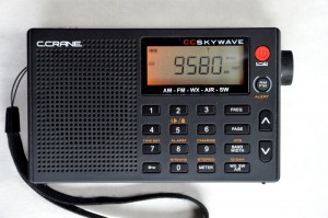
The C.Crane CC Skywave
CC Skywave
Only a couple of weeks before the Christmas holiday of 2014, C. Crane introduced a compact portable that truly impressed me: the CC Skywave. The Skywave is as compact as any other ultralight radio, but adds a host of features that has made it an invaluable radio for my one-bag air travels. The CC Skywave covers the following bands: Shortwave, AM, FM, Weather, and Aviation. It’s a comprehensive toolbox of frequency bands and listening modes which only lacks, sadly, SSB.
Ergonomics are excellent for such a small portable. It’s easy to use, as well: I only needed to reference the well-written manual for a few functions. I find the CC Skywave to be very sensitive on shortwave and mediumwave, rivaling radios that cost much more.
One negative I’ve learned through readers of the SWLing Post is that the first production run of the CC Skywave was prone to overload in the presence of strong local broadcast stations. C.Crane have confirmed that this has been addressed in the latest CC Skywave production run and is no longer an issue. To insure you’re receiving a unit from the latest production run, consider purchasing directly through CCrane.
The CC Skywave is sold by Universal Radio, Amazon.com and directly by C.Crane. Price is $89 US.
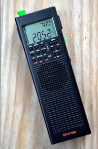
The CountyComm GP5/SSB
CountyComm GP5/SSB (Tecsun PL-365)
CountyComm––a retail distributor of products created primarily for use by the US government––introduced a new shortwave portable late in 2014: the GP5/SSB. The GP5/SSB came about as a result of a large order CountyComm received from a US government department for an “inexpensive, small portable, AM/FM/SW radio with SSB” for emergency supply caches and diplomatic posts. Like its predecessor, the GP5/DSP, the GP5/SSB has a vertical form factor, much like a handy-talky, and a detachable/rotatable ferrite bar antenna that greatly improves AM/mediumwave reception. The GP5 series is limited by a small internal speaker that sounds somewhat tinny; it also lacks a direct entry keypad. Still, with a pair of headphones and some careful memory allocation, the GP5 is a pleasure to use.
If you’re looking for an ultra-portable radio with SSB, then the GP5/SSB is a very good choice. (It may, in fact, be the only ultra-portable SSB choice currently on the market). While the SSB performance can’t compare with larger, pricier receivers, or ham radio transceivers, it’s very good for $80 US. If you’re looking for an emergency communications receiver––something to stash in your vehicle, emergency kit, or bug-out bag––the CountyComm GP5/SSB is a great choice and value. Indeed, that’s who the GP5/SSB was designed for, and why this rig has excellent frequency coverage in all modes, with good sensitivity/selectivity and designed for portable, one-handed operation. In fact, CountyComm has even designed and manufactured (and in the USA!) a robust, protective 1000-Denier case for the GP5/SSB. This case makes it very easy to strap the GP5/SSB to your belt or backpack securely.
The CountyComm GP5/SSB is available from Universal Radio and directly from CountyComm.
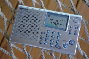
The Sangean ATS-405
Sangean ATS-405
I was surprised this year when Sangean introduced its latest compact/travel receiver, the ATS-405. I had heard rumors that Sangean may have been leaving the shortwave radio scene, so was pleased to learn that Sangean was not only still invested in the hobby, but innovating. Indeed, the ATS-405 has features that have not yet been included on small DSP-powered portables: specifically, the ability to control squelch, tuning mute, and soft mute.
The ‘405 is a decent little radio with a great deal of functionality and features for a rig in its price class. But overall, its performance seems rather mediocre. If you primarily listen to FM, you’ll be pleased. If you’re a mediumwave listener, you’ll be pleased only if you don’t mind the 800/1600 kHz DSP birdies which plagued both of my review units. If you’re primarily a shortwave listener, you’ll need to carry a clip-on wire antenna to bring the sensitivity up to the level of similarly-priced receivers. I also found performance variations between my two review units; an indication that quality control is somewhat inconsistent at the factory.
The Sangean ATS-405 is available via Universal Radio and Amazon.com. Price is $89 US.
Other compact/travel radios
In the 2014 Buyer’s Guide we included several other compact travel radios worth considering: The [original] Kaito KA1103/Degen DE1103, Tecsun PL-310ET, and the Tecsun PL-380 to name a few.
Full-Featured Portables
In the portables market, I believe you get the most value and quality in the $90-250 price class. Most beginners and seasoned SWLs prefer a radio that includes everything necessary to get on the air immediately; all of these radios provide just that. Straight out of the box, you’ll have everything you need to listen to shortwave bands. All of these recommended radios are designed to pick up major shortwave broadcasters with ease, and offer the following features: good frequency coverage; circuitry that helps in the detection of weaker stations; and with a few notable exceptions, the ability to receive single-sideband.
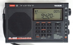
The Tecsun PL-680
Tecsun PL-680
The latest Tecsun full-featured portable––the PL-680––appeared on the market in February this year. Cosmetically, the receiver is nearly identical to the Tecsun PL-600, but with the added features of the Tecsun PL-660. Indeed, in terms of features and comparing them with that of the venerable PL-660, there are no obvious additions on the PL-680. The PL-680 has been improved, however, in its shortwave reception. The PL-680 is both slightly more sensitive and has a more stable AGC (Automatic Gain Control) than the PL-660. If you are primarily a shortwave radio listener and wish to have one of the best sub-$200 receivers currently on the market, the PL-680 may be the rig for you.
On the other hand, if you are primarily a mediumwave DXer and already own the PL-660, you will likely want to pass on the PL-680. The PL-680’s mediumwave reception is simply not as good as that of the PL-660. The PL-660 is both more sensitive and has a lower noise floor on mediumwave.
Note that since its introduction, inventory of the PL-680 has fluctuated; the primary retailer is Anon-Co in Hong Kong and on eBay. Price is $95 US (plus shipping from China).
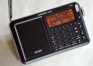
The Eton Satellit
Eton Satellit
Last year, Eton released the Satellit: a new full-featured portable, essentially replacing the venerable Grundig G3, but carrying the name of the flagship Grundig Satellit series.
The Satellit has many of the same functions as the Grundig G3, and has a near-identical form-factor, but sports a new amber backlit display, multiple bandwidths, and a double-jointed telescopic antenna. The Satellit performs admirably on the AM/mediumwave bands, quite well on the shortwave band but, most notably, performs brilliantly on FM. The audio fidelity from the built-in speaker is quite robust; indeed, it’s among the best in its class. The key layout and ergonomics are similar to the Grundig G3 and G5; meaning, the radio is quite simple to use. One negative is that the Satellit mutes between frequencies while tuning, however, this is minimal in the most recently-updated production runs. I’m very pleased that all of the new Eton radios lack the tactile rubber coating found on some previous models, for while the coating works excellently to improve one’s grip on the radio, over time it can become sticky to the touch (if you find this to be a problem, here are several techniques to clean the sticky residue: http://bit.ly/1KQN8TX).
At time of print, the Satellit is generally available for about $180-190 from a variety of retailers, including Universal Radio and Amazon.com.
Other full-featured portables
In the 2014 Buyer’s Guide, we included several other full-featured radios that are still certainly worth considering: The C. Crane CCRadio-SW, Sangean ATS-909X, Sony ICF-SW7600GR, Tecsun PL-600, Tecsun PL-660, and the Tecsun PL-880.
Hybrid Stand-Alone SDR/Tabletops
While tabletop receivers have started to decline with the advent of SDRs, there are many listeners who still prefer a simple, dedicated, stand-alone high-performance receiver with a good tuning knob and clear display, which is to say, a tabletop receiver. Tabletops are designed to perform best with a resonant external antenna.
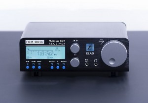
The Elad FDM-DUOr
Elad FDM-DUOr
If you’ve been thinking of purchasing an SDR, but really want a traditional front-panel tabletop receiver, the Elad FDM-DUOr may be for you. I’ve included the FDM-DUOr under the tabletop heading because it is, in fact, a tabletop receiver, with the features of a tabletop such as a front panel, knobs, display, and capability to operate independent of a PC. However, if you choose to hook it to a PC, you unleash a full-fledged SDR and a wide array of features. The FDM-DUOr is built on the same receiver and software as the FDM-S2, one of my favorite sub $1000 SDRs. The FDM-DUOr also sports 10 selectable and customizable filter preselectors and an internal switch box for use with an external transceiver.
At time of print, Elad is seeking FCC approval for the FDM-DUOr in order to distribute these units in the USA. The FDM-DUOr is currently available in Europe via the Elad online store: Price is 899.00 €.

The CommRadio CR-1a
CommRadio CR1-a
US-based manufacturer CommRadio introduced the CR-1 in 2013––an amazingly rugged, portable receiver, and essentially a small tabletop SDR. I’ve used mine in travels and at home; the built-in rechargeable battery will power it for hours, it’s built to a mil-spec standard, and it performs like a champ.
In 2014, CommRadio increased the SDR potential of the CR-1 by updating with a new model: the CR-1a. In 2015, CommRadio continued to add features to the CR-1a through firmware and software upgrades, such as a new Spectrum Viewer SDR application, and 3D-Waterfall for Windows PCs.
CommRadio CR-1a owners only need to update their firmware and download software to use the new feature. The CR-1a is priced at $599.95 US, shipped, and includes a battery through Universal Radio––good value for a quality piece of kit. CommRadio also sells the CR-1a directly through their website.
Other tabletops
In the 2014 Buyer’s Guide, we included several other tabletop radios, including the Alinco DX-R8T and the Icom IC-R75.
SDRs/IF Receivers
If you’re searching for maximum performance for the price, software-defined radios (SDRs) and IF receivers are hard to beat. These small “black box” radios require a computer to unlock performance, none are stand-alone. But while I was never a fan of combining my PC with radio listening, once I starting using an SDR, I never turned back. Now, 90% of the time that I’m on the air, it’s with an SDR. The ease of doing so is incomparable, and the functionality simply incredible.
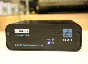
The Elad FDM-S2
Elad FDM-S2 and the new SPF-08 preselector
If you read the Elad FDM-S2 review in the November 2014 issue of TSM you’ll know that this little SDR packs a powerful punch for the price. FDM-S2 performance is uncompromising, comparing favorably to receivers $300-400 more in price. The S2 also provides native DRM decoding; it’s a fine DRM receiver.
Users who live in the vicinity of high-powered AM stations will be pleased to know that Elad has developed an outboard preselector box that pairs with the FDM-S2––the new SPF-08, which covers the amateur radio bands. Elad already has a broadcast band version of the SPF-8 in development. The SPF-08 enclosure is the same size as that of the FDM-S2 and couples with it directly via a port on the back of both units.
Both the Elad FDM-S2 and SPF-08 are available via Elad’s online store: http://ecom.eladit.com/
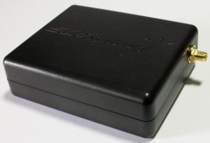
The SDRplay RSP
SDRplay RSP
The SDRplay RSP was one of the most pleasant surprises I encountered in the world of software defined receivers this year. I published a review of the RSP in the May 2015 issue of TSM; in short, I was amazed at the performance of this $149 SDR. While it doesn’t have its own proprietary SDR application, it is compatible with some of the most popular free applications on the market: SDR Console, SDR Sharp, and HDSDR to name a few. SDRplay developers are even testing a Raspberry Pi application for the RSP.
Since the time of my review, SDRplay has updated the RSP to include gapless coverage from 100 kHz to 2 GHz––talk about wideband coverage!
If you have been hesitant to invest in a benchmark SDR, or simply want to explore the world of SDRs on a small budget, the SDRplay RSP is a no-brainer. Without a doubt, it packs a lot of performance in a tiny, affordable package. The SDRplay user community is also very active and routinely pushes the boundaries of this little receiver.
The SDRplay RSP is available at SDRplay.com and, in the US, at Ham Radio Outlet.
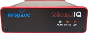
The RFspace Cloud-IQ
RFSpace CloudIQ
The Cloud-IQ is the latest software-defined receiver from the US-based company RFSPACE. The Cloud-IQ offers two modes of operation:
- the “IQ mode,” which provides 24-bit IQ streaming to your PC over an ethernet cable (much like the RFSpace NetSDR).
- the stand-alone “cloud mode,” which includes a built-in internet server. In cloud mode, according to RFSpace, “the receiver performs the tuning and demodulation of signals and transmits the demodulated information back to a PC, OS-X, Linux, or Android client anywhere in the world.”
RFSpace is essentially one of the first SDR manufacturers to include built-in SDR streaming functionality, something that has been somewhat complicated to implement in other SDRs.
The price point is also favorable at $629.95 through Ham Radio Outlet, Amazon, Astroradio and ML&S. Availability has been quite limited this year, but more production runs are planned for the near future. I plan to review the RFSpace CloudIQ in late 2015 or early 2016, as soon as a unit becomes available.
Other SDR/IF receivers
In the 2014 Buyer’s Guide we included several other SDRs and IF receivers worth considering, including the Bonito RadioJet IF-Receiver 1102S, Microtelecom Perseus, and the WinRadio Excalibur. Additionally, note that the affordable Airspy SDR will soon have a new converter to cover HF down to 1kHz–look for a review in 2016.
The Shortwave Radio Index
If you would like to view a comprehensive list of all shortwave radios currently on the market, check out the Shortwave Radio Index (http://swling.com/db).

