Many thanks to SWLing Post contributor, Don Moore–noted author, traveler, and DXer–for the latest installment of his Photo Album guest post series:
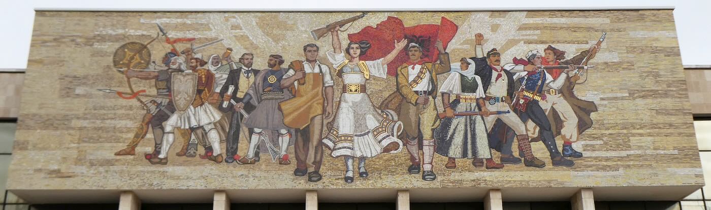
Façade of the National Museum of Albania on Skanderbeg Square
Don Moore’s Photo Album: Albania – Part Two
Bunkers and Bugs
Click here to read Part One: Finding Radio Tirana
More of Don’s traveling DX stories can be found in his book Tales of a Vagabond DXer. Don visited Albania in March 2024.
Albania has a lot to offer foreign visitors. The country has coastal beaches, beautiful mountains and historical sites hundreds and thousands of years old. Tirana is a fascinating city filled with good restaurants and friendly people. It’s inexpensive. The central city is easy to get around on foot. I’m already planning my next visit.
But the number one reason to visit Albania is to see the sites related to the Communist era and the Enver Hoxha dictatorship. I don’t think there is anywhere else where you can get such close insight into what real life was like inside a brutal police state. Indeed, after visiting Tirana, I can’t imagine how anyone could praise dictatorships or say that their own country would be better off under a dictatorship. In Tirana three sites in particular stand out in this regard. And each of them has some interesting displays involving the use of radio.
The House of Leaves
The House of Leaves … the name sounds peaceful and innocent. That was once true. Constructed in 1931, the two-story villa originally served as the first obstetrics clinic in Albania. Then when the Nazis moved in after the Italian surrender in 1943, it was chosen as headquarters for the Gestapo. That might have been a minor blip in the structure’s history, but the Gestapo had remade the building into just what Enver Hoxha’s new government needed: a headquarters for their secret police.
The dreaded Sigurimi would occupy the building for nearly five decades. But that was supposed to be a secret, so no one could say what the villa really was, even though everyone knew. So it became known as The House of Leaves from the vines that covered the outer walls. Even then, the name was mostly whispered among the closest friends. It wasn’t safe to pay much attention to the building.
After the Communist regime fell in 1991, The House of Leaves mostly sat unused. Then, in 2014 the Albanian Ministry of Culture announced it would be turned into a museum telling the story of Sigurimi and its operations. The Museum of Secret Surveillance opened in 2017 and three years later was awarded the European Museum of the Year award by the Council of Europe.
The museum has many rooms focusing on various aspects of Sigurimi’s work. My favorite was one filled with electronics used to monitor and record conversations by suspected malcontents.
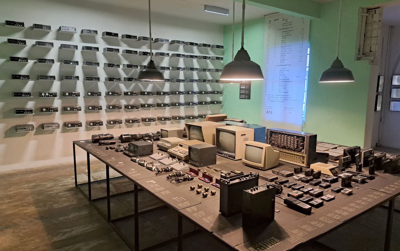
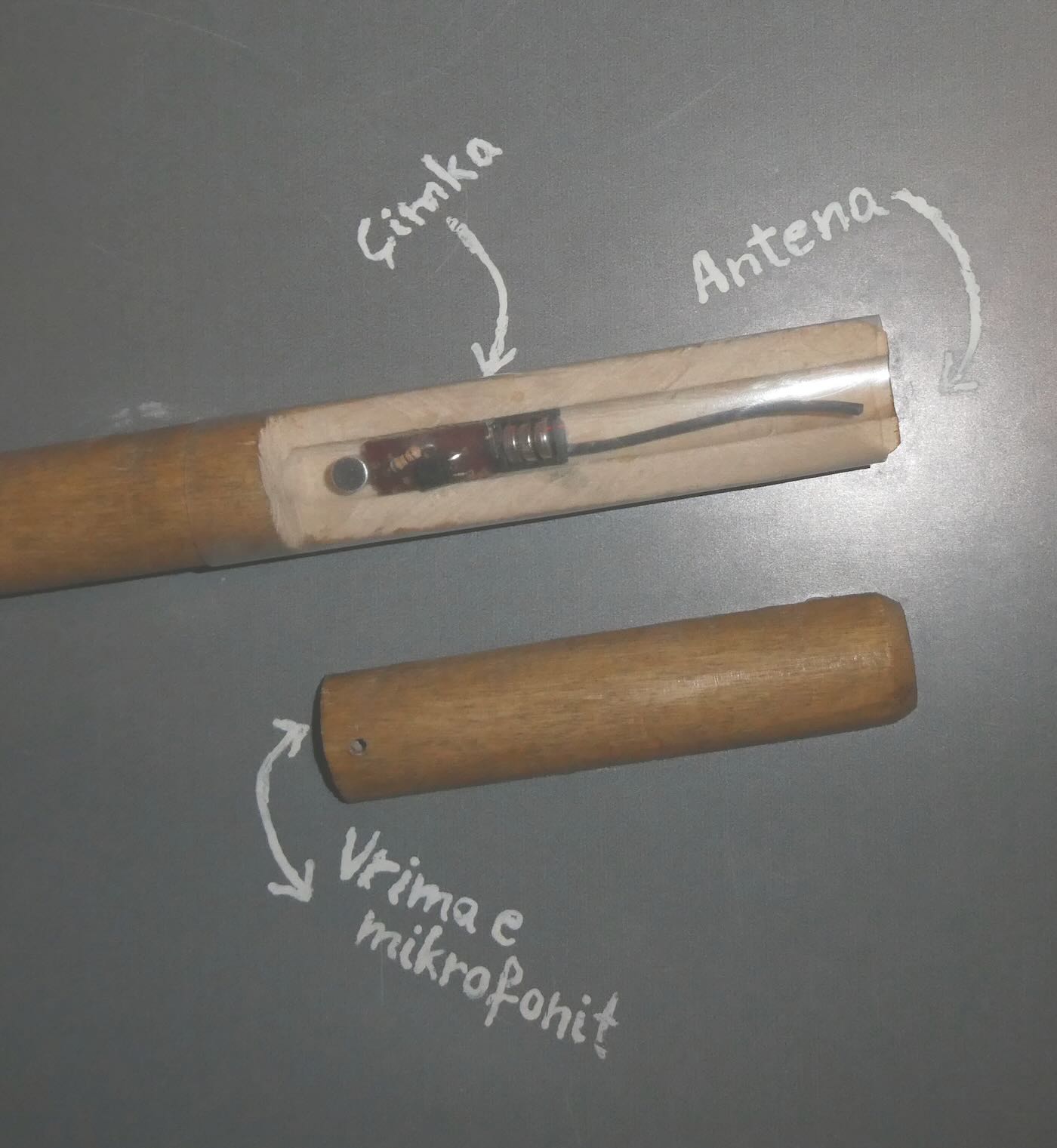
The key to monitoring someone was placing a radio transmitter bug in the suspect’s home. The Sigurimi made their own bugs in a workshop in The House of Leaves. They were particularly proud of the tiniest ones, which could very easily be hidden.
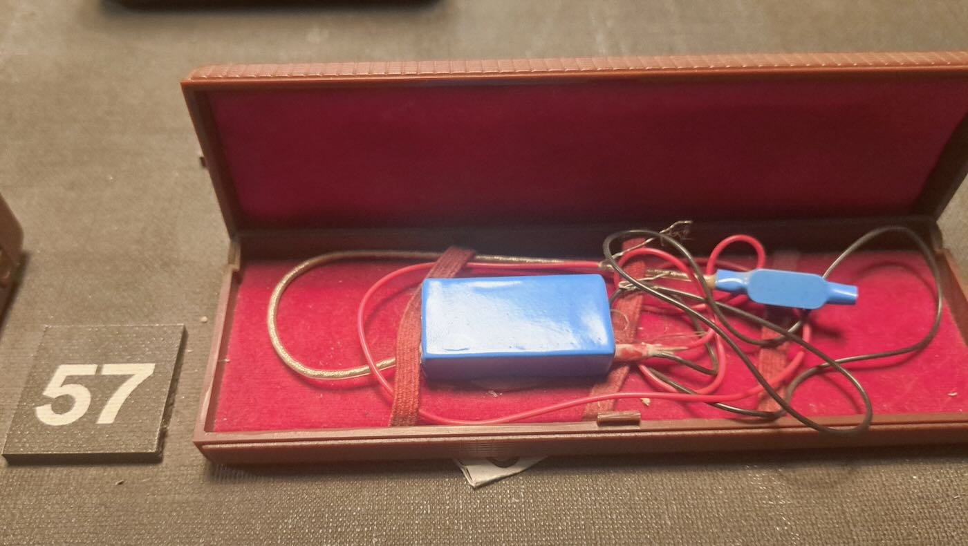
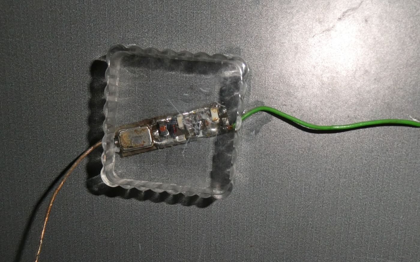
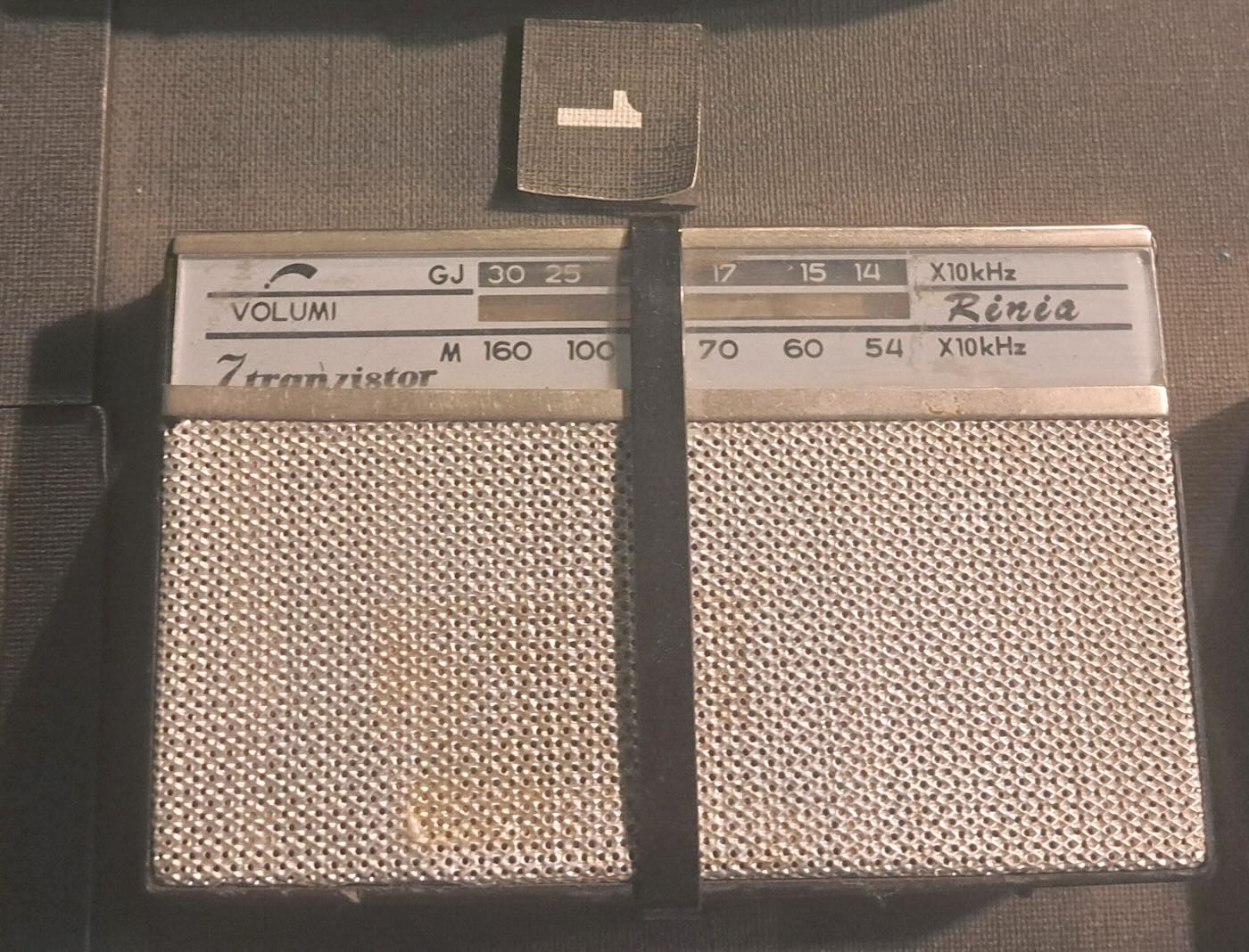
The bugs were usually placed inside a small piece of wood that could be placed under a table or chair. The effective range was only about two hundred meters, so monitoring posts had to be in the same building or nearby. The Sigurimi would either recruit a neighbor or persuade a neighbor to host a Sigurimi agent to monitor the recordings. Rinia brand transistor radios made in Romania were the preferred receiver. They were inexpensive and could easily be modified to receive the desired frequency. And they were common enough that possession of one didn’t mark a person as a government agent. Agents usually listened in on headphones while also making a recording of the conversation.
 In some cases, homemade amplifiers were used to boost the weak signals produced by the tiny bugs.

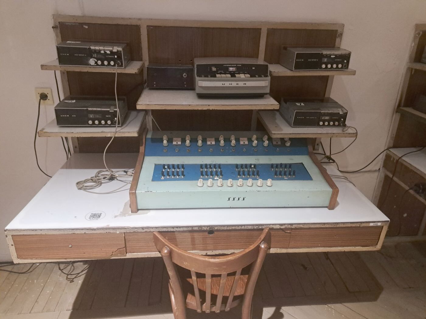
Recordings of conversations of interest were taken back to The House of Leaves for further investigation at monitoring posts such as this one.
The Bunkers
Enver Hoxha knew that tiny Albania could never support an army large enough to repel an outside invasion. His experience as a guerilla in World War II, on the other hand, had convinced him that an armed hostile populace could do the job. Albania was, after all, the only occupied country to retake its own capital without any outside help. So Hoxha based Albania’s national defense on making sure that invading the country would be so difficult and painful that no one would dare attempt it.
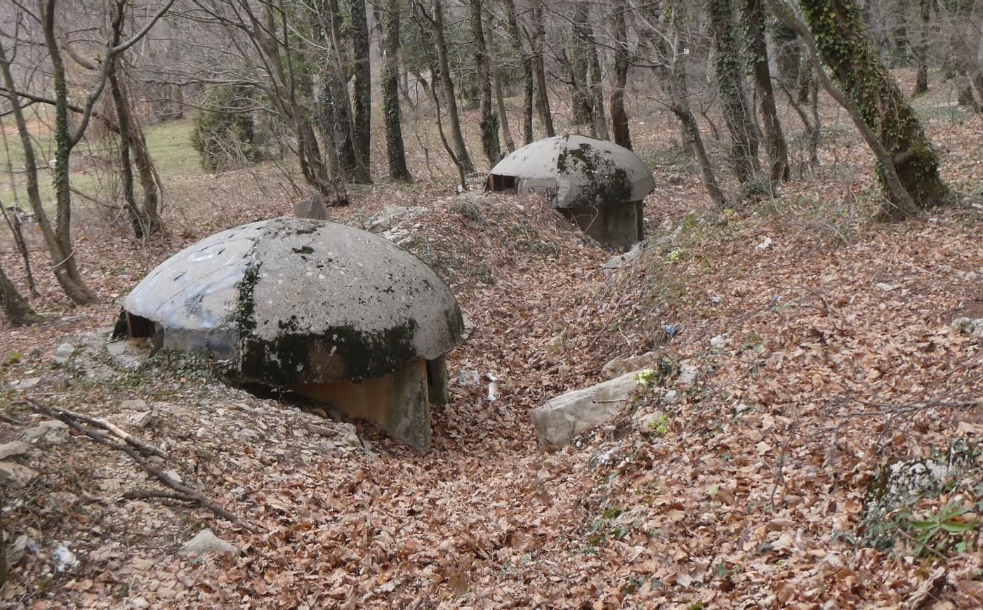
A key part of that policy was constructing concrete bunkers. Hoxha’s goal was to construct 750,000 of them – approximately one for every four Albanians at the time. Just how many were actually constructed is not known, but the number was in the hundreds of thousands. And they were built everywhere – in farms, in forests, in villages, and in cities.
Most were the three-meter-wide Qender Zjarri type, just large enough to give two or three combatants a concealed firing position. Depending on the location these were built individually or else in small clusters. Today, a fun activity while traveling by bus through Albania is seeing how many you can spot. Occasionally these bunkers are used for storage but there are so many that most are abandoned other than the occasional visit by local teenagers. Evidently, they’re the cool place for losing one’s virginity.
The second type of bunker was the eight-meter-wide Pike Zjarri, intended to serve as local command centers. Being larger, many of these have been put to other uses. And then there were the big bunkers, huge complexes of underground rooms and tunnels where officials would take refuge and continue to run Albania’s government. But today’s Albania is not concerned with repelling foreign invaders. Instead it welcomes them in the form of tourists. And so two of the biggest bunker complexes in Tirana have been turned into museums. And both of them contain some interesting radio memorabilia.
Enver’s Refuge
The biggest bunker was a vast underground complex built in the 1970s inside the base of a mountain on the eastern outskirts of Tirana. Construction was so secret that this bunker’s existence wasn’t even known publicly until the 1990s. This was where Enver Hoxha and other top officials would have gone in the event of an invasion or nuclear attack. It had over one hundred rooms on five levels with its own power and water systems. The entrance passed through a decontamination station where anyone entering could wash off the fallout if a nuclear bomb had already been dropped. (Or so they hoped.)
The inside is a labyrinth of hallways and small rooms used for everything from communication centers to support services. There is even a small auditorium where the Albanian legislature could meet. Enver Hoxha and the prime minister had small spartan private apartments. Other officials, guards, technicians, and servants slept in dormitories. Of course, the facility was never used. It’s believed that Enver Hoxha only visited three times – once when it was completed in 1978 and then two more times for drills.
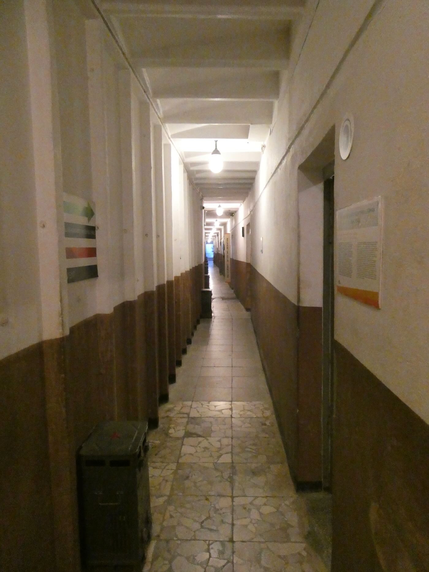
One of many hallways in the Enver Hoxha’s refuge.
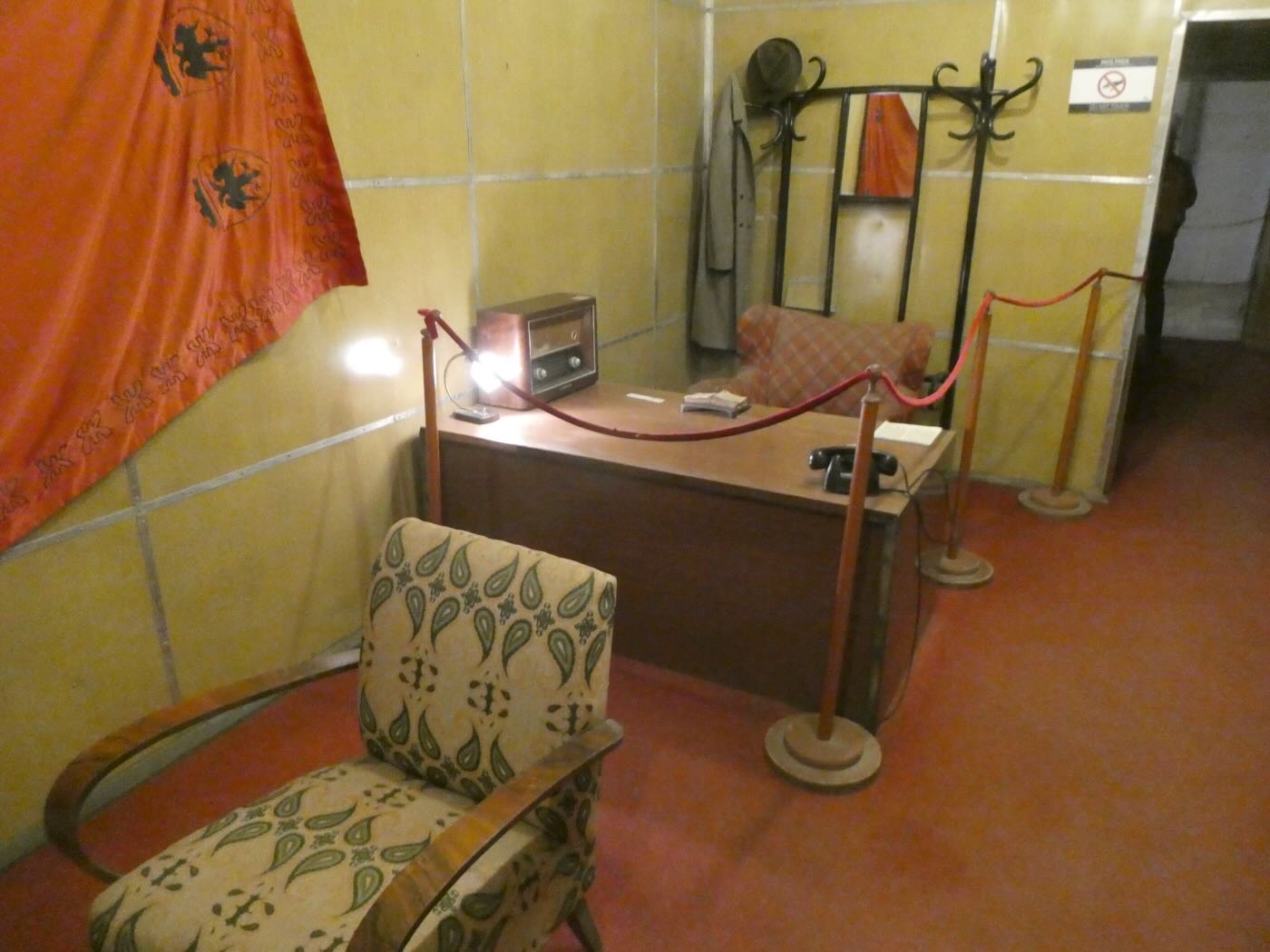
Enver Hoxha’s office in the big bunker. The desk has the same Chinese-made Red Lantern Model 269 receiver that I saw at the Radio Bar Tirana.
The Albanian military continued to use the facility for several years after the Communist government fell in 1991. After that it was locked up. Then in 2014 a pair of journalists came up with the idea of making it into a museum which was named Bunk Art. But it’s a history museum, not an art museum. Some rooms were left unchanged to show the structure’s original purpose. Others were filled with exhibits on Albanian history, the Italian invasion, the Communist period, and life under Communism. And those exhibits include a few interesting radio items.
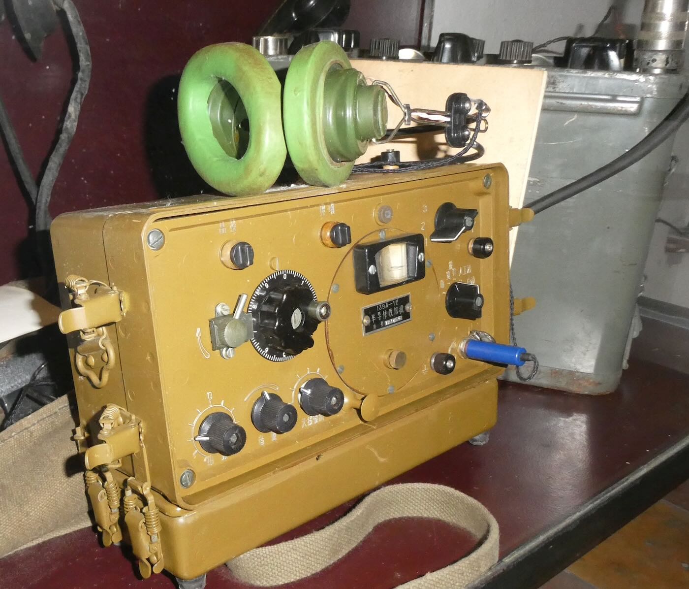
According to the display, this was one of two portable transceivers in possession of Xhevdet Mustafa when he was killed by the Sigurimi on the beach south of Tirana in 1982. The display didn’t make clear who Mustafa was working for.
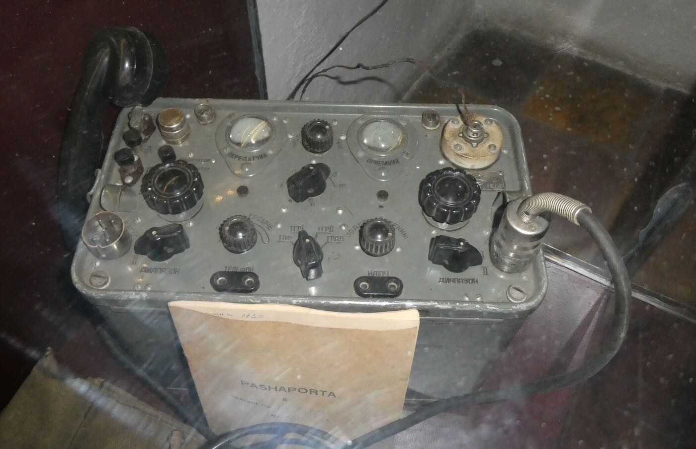
On several occasions in the early 1950s the CIA tried to insert small bands of Albanian agents into the country, mostly without success. This Russian-made transceiver was part of the gear that came with a small group of agents parachuted into Albania in 1953. The group were all killed or captured when they landed. With help coerced from the prisoners, the Sigurimi used this radio for several months to trick the CIA into continuing to air-drop supplies into the mountains.
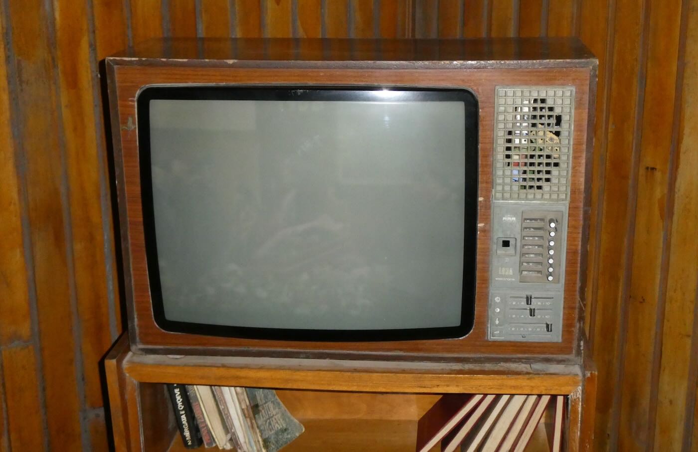
This black-and-white Albanian-made TV was configured at the factory to only receive Albanian channels. However, clever Albanians figured out ways to use small electronic circuits (called kanoce) that overrode those limits. Albanians along the coast were able to receive TV from Italy while those in border areas could receive Yugoslav or Greek TV.
The Downtown Bunker
The original Bunk Art proved so popular with Albanians and foreign visitors that in 2016 it was renamed Bunk Art 1 and a second location, Bunk Art 2, was opened in the city center. This bunker had been built under the city streets near The House of Leaves and had been intended for use by the Ministry of Internal Affairs. It consisted of a single level with several branching hallways lined with small rooms. Today, it’s a museum telling the story of the Ministry (of which the Sigurimi was just one part) until its dissolution in 1991.
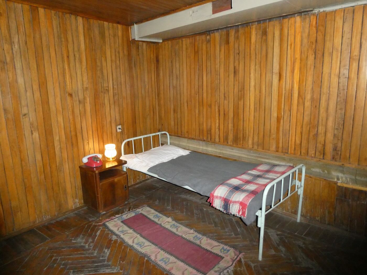
This bunker was also configured for a long-term stay. The Minister of Internal Affairs had this private bedroom.
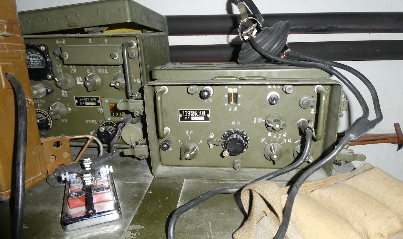
Some Chinese-made radio equipment used by the ministry.
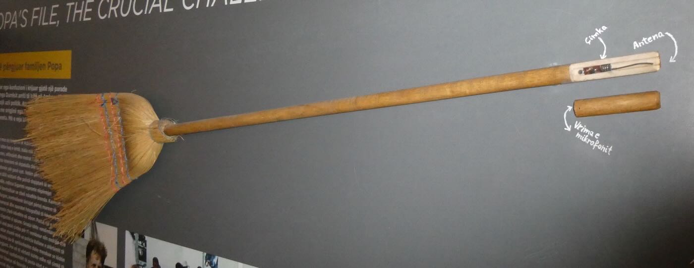
The Broom Bug
On 12 December 1985, the streets of Tirana were crowded with people out to watch a large patriotic parade which just happened to pass by the Italian embassy. Two women and four men dressed in fashionable western clothes and chatting in Italian among themselves snaked their way through the crowd to the door of the embassy. The Albanian police monitoring the door didn’t try to stop them. Obviously, they were Italian tourists or embassy workers. Except they weren’t. The sisters and brothers of the Popa family had long been persecuted by the Albanian government as their parents had collaborated with the Italians during the war. And now the six children wanted political asylum.
The Italians were willing to resettle the family in Italy but the Albanian government refused to give them permission to leave. Instead Albania demanded that the siblings be turned over to its police, which the Italians refused to do. The family would live in the embassy for 4 ½ years until the Albanian government finally agreed to let them go. In the meantime the Albanians kept a strong police and military presence in the neighborhood surrounding the embassy.
The Sigurimi wanted to know what was going on inside so they recruited an Albanian maid who worked at the embassy to help them. She was given five bugs and instructions to hide them in the usual places like behind paintings and under tables. They knew the Italians would find these and that was fine. It would give the Italians false confidence that they had found all the bugs. The real bug was concealed in a special new broom that the maid brought in and left in a closet next to where the Popa siblings stayed. Each day she was given a freshly charged battery to swap with the depleted one inside the broom. The Italians never discovered the bug-in-a-broom. The Popa siblings were finally allowed to leave the embassy for Italy on 3 May 1990.
Links and Other Info