Many thanks to SWLing Post contributor, Mike Ladd with SDRplay, who shares the following guest post:

Basics to decoding WEFAX using an RSP and SDRuno
by Mike Ladd
SDR I use:
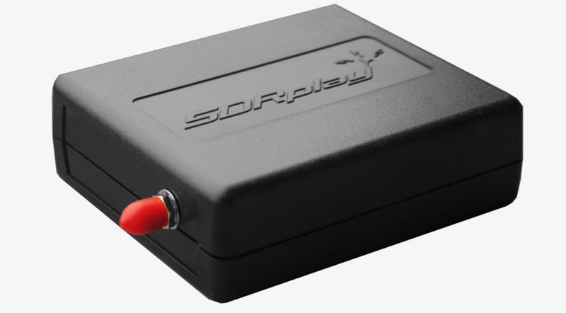
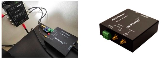
RSPduo from SDRplay using the Hi-Z input. Any model RSP’s can tune WEFAX transmissions. https://www.sdrplay.com/rspduo/
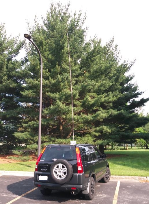
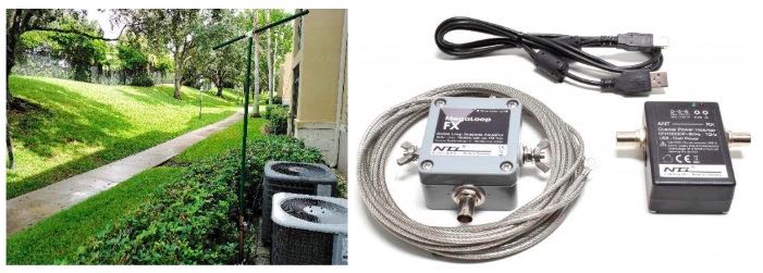
Antenna I use: Megaloop FX from Bonito. In an Inverted delta loop configuration pointed N/E-S/W. Any good antenna placed outdoors should be fine. It’s all about the SNR, not your S-meter reading. https://www.bonito.net/hamradio/en/mega-loop-fx/
Software:
SDRuno v1.32
SDRuno is an advanced Software Defined Radio application platform which is optimized for use with SDRplay’s range of Radio Spectrum Processing receivers.
https://www.sdrplay.com/downloads/
VBcable (donationware) vPack43
Transfers audio, digitally from one application (SDRuno) to another (Black Cat HF weather Fax) with zero loss.
https://www.vb-audio.com/Cable/
VAC (paid for use) v4.60
Transfers audio, digitally from one application (SDRuno) to another (Black Cat HF weather Fax) with zero loss.
https://vac.muzychenko.net/en/
https://www.sdrplay.com/docs/SDRuno_VAC.pdf
Black Cat HF Weather Fax (paid for use) beta 19
Decodes and produces images from the WEFAX transmissions from the output of SDRuno using a virtual audio cable.
Use the discount link available here
http://blackcatsystems.com/register/black_cat_hf_weather_fax_sdrplay_promo.html
https://www.blackcatsystems.com/software/hf_weather_fax.html
Black Cat Uno UDP
UnoUDP allows you control SDRuno’s VFO frequency from within Black Cat HF Weather Fax scheduler. This is done over a virtual com port pair using a virtual com port emulator. http://blackcatsystems.com/download/UnoUDP.zip
VSPE or COM0COM
VSPE is a paid for use app. COM0COM is completely free. Either one of these applications will work. A virtual com port emulator allows you to create a virtual com port. The pair will internally link Black Cat Weather Fax decoder to SDRuno’s using UnoUDP as the transport protocol.
VSPE http://www.eterlogic.com/Products.VSPE.html
https://www.sdrplay.com/docs/SDRuno_VSPE.pdf
COM0COM http://com0com.sourceforge.net/
https://youtu.be/dZg7puQ9Ajk
Introduction:
(some text taken and edited from various website)
This document is not a definitive guide to the WEFAX protocol, the process of decoding WEFAX images or reading a synoptic weather chart https://youtu.be/kzfNSvQREu8. This is only a collection of information that I have found scatter throughout the internet and re-compiled into a document, this document. Expect typographical mistakes, inaccuracies, or omissions.
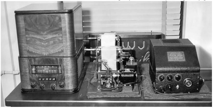
WEFAX is an analog mode for transmitting monochrome images. It was the predecessor to slow-scan television (SSTV). Prior to the advent of the commercial telephone line “fax” machine, it was known, more traditionally, by the term “radio facsimile”.
Facsimile machines were used in the 1950s to transmit weather charts across the United States via land-lines first and then internationally via HF radio. Radio transmission of weather charts provides an enormous amount of flexibility to marine and aviation users for they now have the latest weather information and forecasts at their fingertips to use in the planning of voyages.
Radio fax relies on facsimile technology where printed information is scanned line by line and encoded into an electrical signal which can then be transmitted via physical line or radio waves to remote locations. Since the amount of information transmitted per unit time is directly proportional to the bandwidth available, then the speed at which a weather chart can be transmitted will vary depending on the quality of the media used for the transmission.
Radio fax data is available from the web on sites such as the ones hosted by the National Oceanic and Atmospheric Administration (NOAA). https://tgftp.nws.noaa.gov/fax/marine.shtml Radio fax transmissions are also broadcasted by NOAA from multiple sites in the country at regular daily schedules https://www.nws.noaa.gov/os/marine/rfax.pdf. Radio weather fax transmissions are particularly useful to shipping, where there are limited facilities for accessing the Internet.
Black Cat HF Weather Fax is a program that decodes WEFAX (Weatherfax, HF-FAX, Radiofax, and Weather Facsimile) transmissions sent from fixed locations around the globe.
A fax is transmitted line by line, typically at a rate of 120 lines per minute, or half a second per line. For example, to send a weather chart, you would start in the upper left corner. You would send the value of that pixel (dot), black, white, or perhaps a shade of gray. Then you would move over one pixel to the right, and send that pixel, and so on, until you reach the edge of the chart. Then you’d move all the way back to the left edge, and move down slightly, one line, and repeat the process.
Each pixel is converted into a certain audio frequency or tone. By convention, a tone of 1500 Hz represents black, 2300 Hz represents white, and frequencies in-between represent shades of gray. So if you listen to a fax transmission, you’ll hear the different tones as each pixel is present. For example, listen to a chart with mostly white background being sent. You’ll hear mostly the high pitch 2300 Hz, and some lower (1500 Hz) blips as each black pixel is sent. When a horizontal line is sent, you’ll hear a long half second burst of 1500 Hz, since the line is all black.
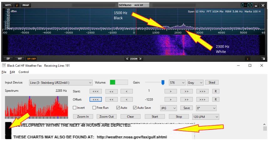
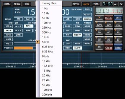
The transmitting station frequency modulates the carrier. That is, when a black pixel is transmitted, the carrier shifts down 400 Hz. When a white pixel is transmitted, the carrier shifts up 400 Hz. For a medium gray pixel, it stays on the assigned frequency. This is how most fax transmissions are made. Since we’re tuning it in SSB, it sounds to us as if the station is transmitting a variable frequency audio tone. The two processes are identical. This accounts for the confusion regarding what frequency to tune the radio to in order to properly decode the fax transmission. Different stations list their frequency in different ways. It is important to remember that a black pixel produces a 1500 Hz tone, and a white pixel produces a 2300 Hz tone within the AUX SP.
The setup works as follows. SDRuno demodulates the received signal. The demodulated audio is piped from SDRuno using virtual audio cable and sends it to the HF weather fax decoder. HF weather fax decoder receives this audio from the virtual audio cable that was demodulated from SDRuno and processes it, producing a picture on the screen
HF weather fax decoder can also set the VFO (tune) frequency of the RSP in SDRuno. This is done over the virtual com port pair using the UnoUDP application as the transport.
SDRuno can internally emulate a Kenwood TS-480, UnoUDP sends the Kenwood TS-480 serial commands via UDP over the virtual com port pair in order to set the frequency selected from the HF Weather Fax Scheduler option over to SDRuno.
You will need to install and configure the following applications.
1: A virtual audio cable.
2: A virtual com port emulator (If you would like HF Weather fax to communicate with SDRuno).
3: UnoUDP (If you would like HF Weather fax to communicate with SDRuno using the virtual serial emulator).
4: HF Weather Fax.
5: A simple wire antenna placed outdoors.
Virtual Audio Cable:
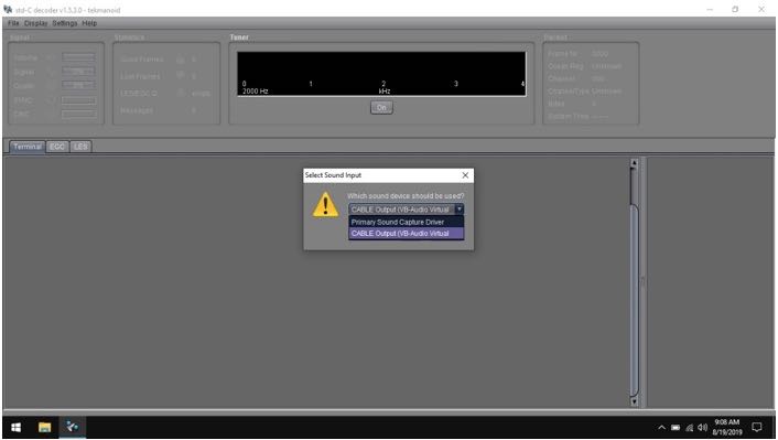
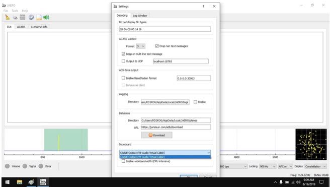
A virtual audio cable allows you to pipe the audio from one application (SDRuno) into another application (a decoder like HF Weather Fax) digitally. I will assume SDRuno is already installed with your device attached and functioning properly.
You can now download a virtual audio cable package. If you already have a virtual audio cable package installed, you can skip to the next section. If you don’t have a virtual audio cable application installed, you only need to choose one and install only one of the two that are available.
Close any running apps, install the virtual audio cable and reboot your computer. When your computer boots to your desktop, your computer will now have a virtual audio cable pair installed on the system.

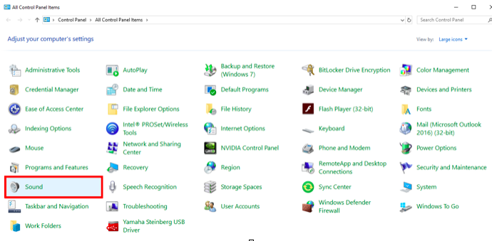
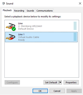
You can verify it the installation by going to your Control Panel and double clicking the Sound icon. VB-Cable and Virtual Audio Cable will only install a single virtual audio cable pair, one is for the input (Recording) and one is for the output (Playback). A single pair is all that is needed (as shown below).

Virtual Serial Port:
A virtual com port emulator is only needed if you would like Black Cat HF Fax decoder the ability to tune the station in SDRuno when you double click a station name in the HF Fax Decoder scheduler.
Please use the links provided (additional PDF’s and YouTube videos) on Page 2 of this document for an installation / configuration walkthrough.
You can download my WEFAX frequency bank for use in SDRuno below should you choose not to use a virtual com port emulator. https://signalsacrossthepond.com/download/mike-kd2kog-sdrplay-complete/
Download Black Cat HF Weather Fax and UnoUDP:
Download the latest HF Weather Fax beta package and the UnoUDP application from the link provided on Page 2 of this document. I suggest making one main folder called HFfax and two subfolders within HFfax for each of the applications. One folder is for the HF Weather Fax Decoder and the other folder is for the UNO UDP transport application.
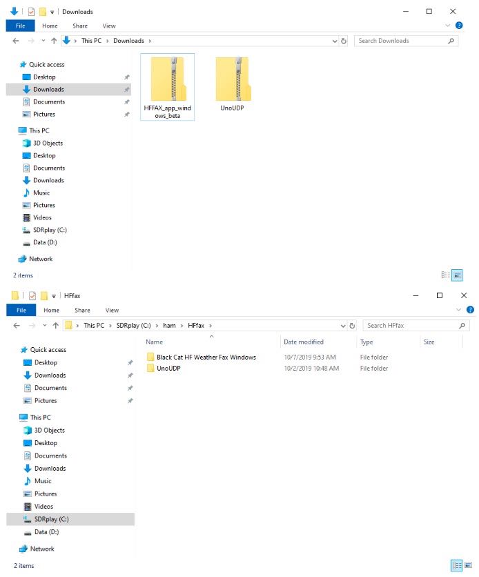
Double click the HF Weather Fax beta ZIP file you downloaded and extract the full contents of this ZIP into the folder you created on your local drive. Right click the “Black Cat Weather Fax” EXE file and send a shortcut to your Desktop.

Double click the UnoUDP zip file you downloaded and extract the full contents of this ZIP into the folder you created on your local drive. Right click the “UnoUDP” EXE file and send a shortcut to your Desktop.
You should have two shortcuts on your desktop, One for the decoder and one for the transport app.
Black Cat UnoUDP:
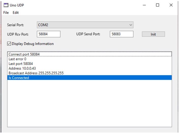
HF Weather Fax needs a way to communicate with SDRuno, this is done via UnoUDP and the virtual com port emulator.
Launch UnoUDP with the above configuration. Set your UDP Receive port to 58084 and your UDP send port to 58083. UnoUDP must be left running in the background, this will control SDRuno. You can minimize the application or right click the shortcut and have UnoUDP auto minizine on launch.
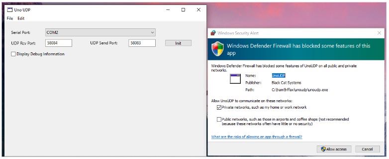
You should see a Firewall popup prompt asking permission to allow UnoUDP to pass data within the system. You must allow this traffic to pass or external control of SDRuno will not be possible from the HF Weather Fax decoder scheduler.
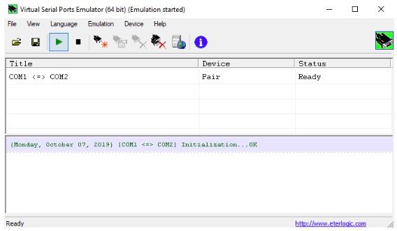
Assign 1 of the 2 com ports from the virtual com port emulator to UnoUDP (the 2nd com port will be assigned to SDRuno). My com port pair is Com 1 and Com 2, SDRuno uses Com1 and UnoUDP uses Com 2.
Black Cat HF Weather Fax:
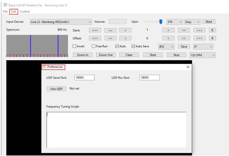
HF Weather Fax needs to be configured in order to communicate with UnoUDP, this is done via the UDP settings. Click “Edit” and “Preferences” Set the UDP Send port to 58084 and the UDP Receive port to 58083.
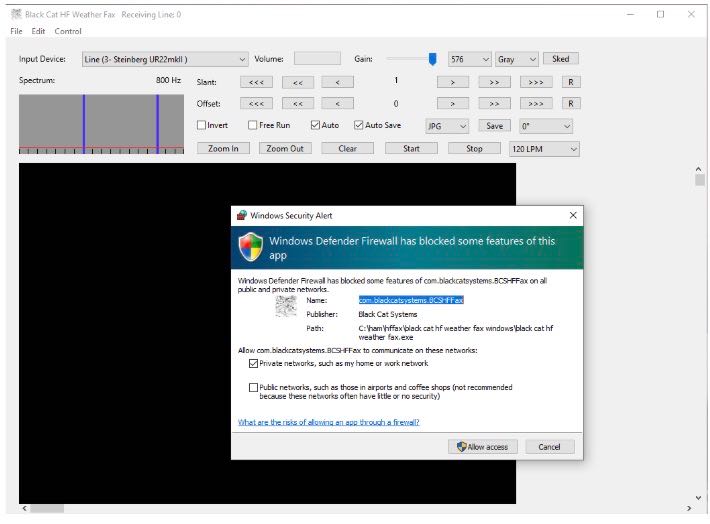
You should see a Firewall popup prompt asking permission for HF Weather Fax to pass data within your system. You must allow UDP traffic to pass or external control of SDRuno will not be possible from the HF Weather Fax decoder scheduler.
SDRuno:
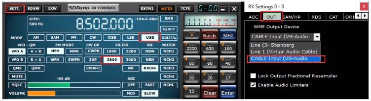
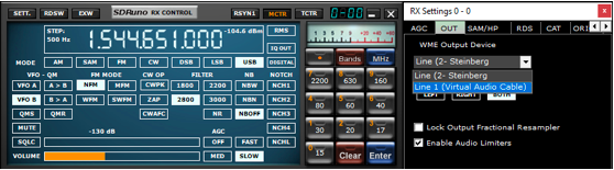
SDRuno needs its Output assigned to the Virtual Audio Cable. The output can be changed via the RX CONTROL panel, clicking the SETT. button on the top left and clicking the OUT tab.
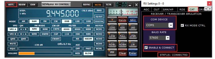
SDRuno needs a com port assigned so it can be externally controlled. The serial port is assigned via the RX CONTROL panel, clicking the SETT. button on the top left and clicking the CAT tab.
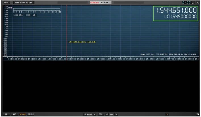
I recommend running the RSP in LOW-IF mode, this is selected via the MAIN panel. This reduces the need to track separation between the Tuned frequency and LO (local oscillator) https://youtu.be/Fsns4P3JxrM
LOW-IF mode also minizines the LO being placed outside of the desired preselect filter of the device in use, Remember the preselect filter is automatically enabled based on the LO frequency https://youtu.be/w-vkiVp7Q4E
I also recommend leaving the IF AGC enabled and placing the RF GAIN as high as possible without causing an ADC OVERLOAD warning within the MAIN panel. If an ADC OVERLOAD warning appears, back the RF GAIN down.
https://www.sdrplay.com/wp-content/uploads/2018/06/Gain_and_AGC_in_SDRuno.pdf
Your first WEFAX decode (Using UnoUDP)
Launch UnoUDP and minimize it.
Launch Black Cat HF Weather FAX.
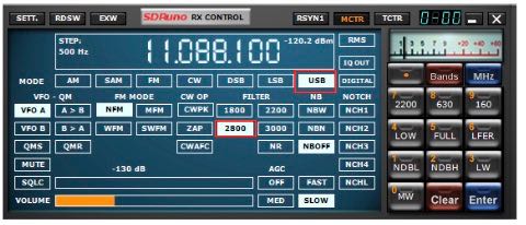
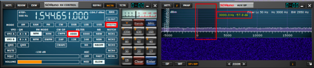
Launch SDRuno. Set the mode to USB and the filter width to 2.8k
HF weather fax will not set the mode or filter width at this time.
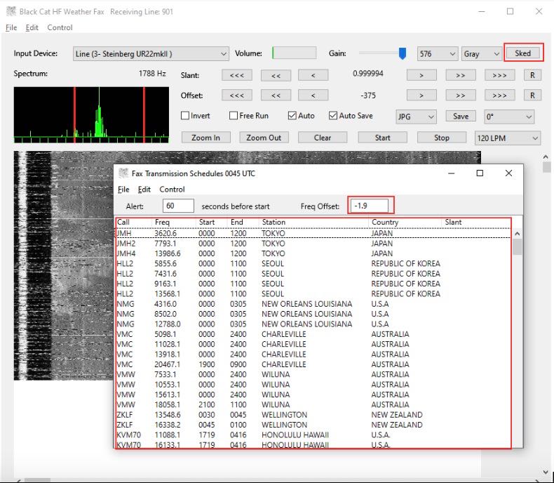
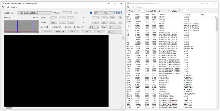
Click the Sked button in Black Systems HF Weather Fax. A current WEFAX transmission schedule will appear. Stations listed in White are either scheduled to transmit or about to transmit based on your computers clock. Stations show in Grey at the bottom of the list are currently off the air or not transmitting.
In the Freq Offset: box enter -1.9 and hit enter (Reason for this is on Page 5).
Click any of the stations listed in the Fax Transmission Schedule and it will automatically tune SDRuno to the correct frequency.
Black Cat HF Weather Fax folder will have a file named “Black Cat HF Weather Fax Docs” Please view this file to understand some of the advanced features available.
Your first decode (Without UnoUDP)
Launch Black Cat HF Weather FAX.
Launch SDRuno.
Navigate to the Memory Panel (MAIN panel and click the MEM PAN button)
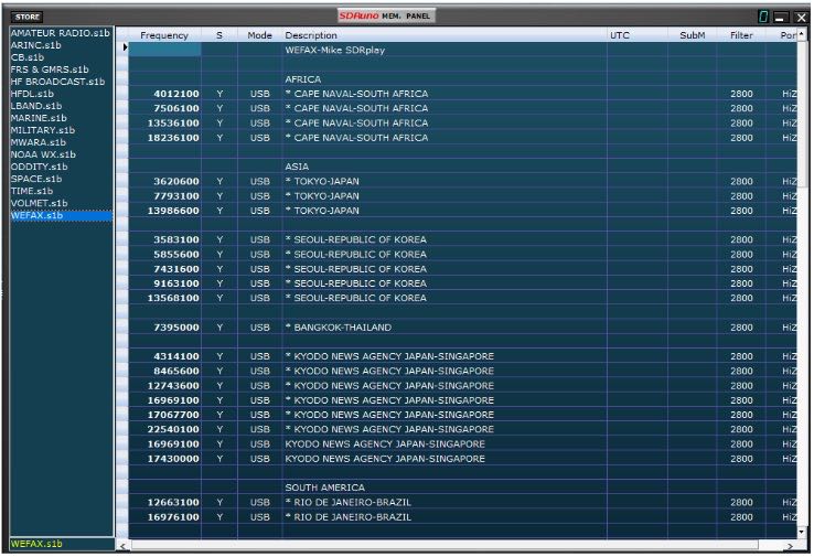
Right click the Memory panel and select “Open bank”. Navigate you C drive telling SDRuno the location of WEFAX.s1b
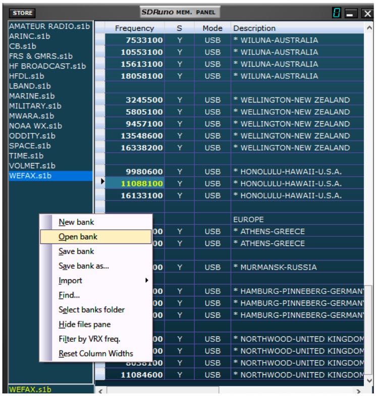
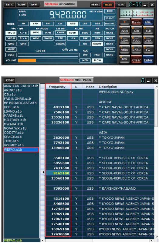
Double click any of the frequencies shown within the WEFAX bank and SDRuno will set the correct mode and tune that station. My WEFAX.s1b file defaults to the Hi-Z port. If your device lacks a HI-Z input, navigate to the port section within the memory panel, double click the stations port you want to edit and change it to the correct port that’s available or in use for your device. Right click the memory panel and “Save bank” to save the changes.
To use my SDRuno WEFAX frequency bank properly. The MCTR button must be enabled within the RX CONTROL panel, enabling this option allows you to double click and tune a station that is stored within the WEFAX bank. Make sure the LO is not locked in the MAIN panel (LO LOCK).
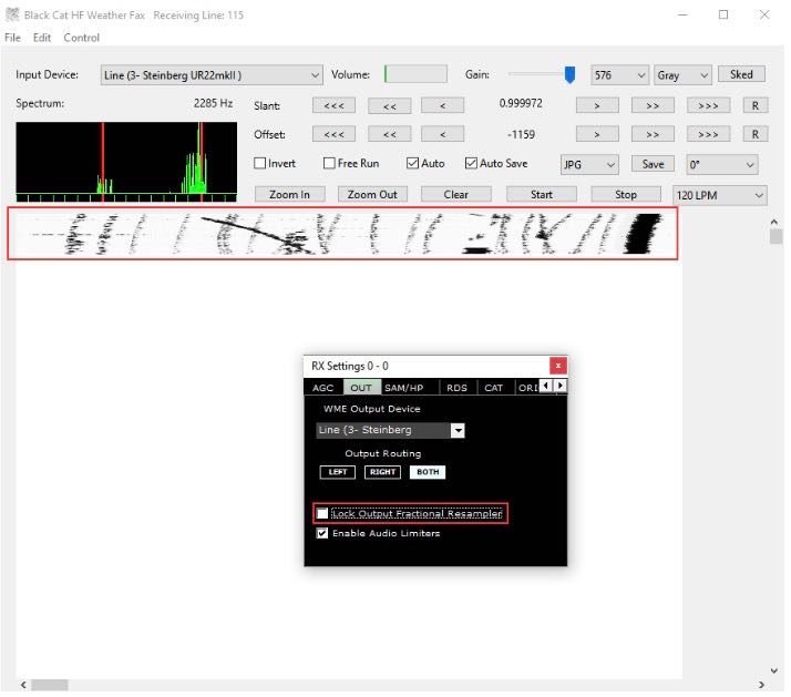
If a decoded WEFAX image looks blocky or skewed or possibly pixeled, I recommend that the lock output fractional resampler option is enabled in SDRuno. You can enable this from the RX CONTROL panel, clicking the SETT. button on the top left and clicking the OUT tab.

I hope this document helped guide you in getting started with decoding WEFAX transmissions from around the world. I am sure I missed some key features, remember this is only a primer/basics to decoding WEFAX. I do have an accompanying video located here
Warmest of 73,
Mike-KD2KOG
Disclaimers
SDRPlay modules use a Mirics chipset and software. The information supplied hereunder is provided to you by SDRPlay under license from Mirics. Mirics hereby grants you a perpetual, worldwide, royalty free license to use the information herein for the purpose of designing software that utilizes SDRPlay modules, under the following conditions:
There are no express or implied copyright licenses granted hereunder to design or fabricate any integrated circuits or integrated circuits based on the information in this document. Mirics reserves the right to make changes without further notice to any of its products. Mirics makes no warranty, representation or guarantee regarding the suitability of its products for any particular purpose, nor does Mirics assume any liability arising out of the application or use of any product or circuit, and specifically disclaims any and all liability, including without limitation consequential or incidental damages. Typical parameters that may be provided in Mirics data sheets and/or specifications can and do vary in different applications and actual performance may vary over time. All operating parameters must be validated for each customer application by the buyer’s technical experts. SDRPlay and Mirics products are not designed, intended, or authorized for use as components in systems intended for surgical implant into the body, or other applications intended to support or sustain life, or for any other application in which the failure of the Mirics product could create a situation where personal injury or death may occur. Should Buyer purchase or use SDRPlay or Mirics products for any such unintended or unauthorized application, Buyer shall indemnify and hold both SDRPlay and Mirics and their officers, employees, subsidiaries, affiliates, and distributors harmless against all claims, costs, damages, and expenses, and reasonable attorney fees arising out of, directly or indirectly, any claim of personal injury or death associated with such unintended or unauthorized use, even if such claim alleges that either SDRPlay or Mirics were negligent regarding the design or manufacture of the part. Mirics FlexiRFTM, Mirics FlexiTVTM and MiricsTM are trademarks of Mirics .
SDRPlay is the trading name of SDRPlay Limited a company registered in England # 09035244.
Mirics is the trading name of Mirics Limited a company registered in England # 05046393
Do you enjoy the SWLing Post?
Please consider supporting us via Patreon or our Coffee Fund!
Your support makes articles like this one possible. Thank you!