Radio Waves: Stories Making Waves in the World of Radio
Because I keep my ear to the waves, as well as receive many tips from others who do the same, I find myself privy to radio-related stories that might interest SWLing Post readers. To that end: Welcome to the SWLing Post’s Radio Waves, a collection of links to interesting stories making waves in the world of radio. Enjoy!
Many thanks to SWLing Post contributors David Iurescia, Mark Erdle, and the Southgate ARC for the following tips:
WEST CHESTER, Ohio — Imagine, if you will, a voice so strong that it shakes the very foundations of global tyranny.
In the early days of World War II, a group of Americans, including President Franklin Roosevelt, actor and director John Houseman and Cincinnati entrepreneur Powell Crosley Jr. imagined such a voice, one that could counter Nazi propaganda in Hitler’s own backyard.
They named it The Voice of America.
Today, the National Voice of America Museum of Broadcasting, 8070 Tylersville Road, occupies the site from which the service beamed its message around the world for 50 years beginning in 1944, recounting its history and remembering the people, especially Crosley, who made it possible. [Continue reading…]
Saturday, December 11, 2021
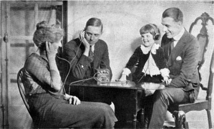
On a cold winter night on December 11, 1921, members of the Radio Club of America were able to send the first amateur radio message from a small shack in Greenwich, CT to be received by American Paul Godley in Ardrossan, Scotland. This transatlantic test proved the value of shorter wavelengths – long considered worthless to long distance communications and through their success ushered in the age of global shortwave radio communications. The 1921 message was sent one-way. Acknowledgment of Paul Godley’s reception of 1BCG’s massage was sent back to the US via the Marconi high power radio transmitter in Wales.
The Antique Wireless Association, in association with the Vintage Radio and communications Museum of Connecticut (VRCMCT) in Windsor, CT, the Radio Club of America, the American Radio Relay League, and the Radio Society of Great Britain, participated in the 100th Anniversary special events held Saturday, December 11, 2021.
For the 75 th anniversary celebration of the 1BCG accomplishment in 1996, AWA members Bob and Mike Raide constructed a replica of the 1921 transmitter. For this 100th celebration, AWA Museum Staff restored the replica. The VRCMCT in Windsor CT has graciously offered to host AWA operation of the replica transmitter during the evening of December 11th. The 1BCG replica transmitter was placed on public display at the VRCMCT Museum during the day of Saturday December 11, 2021. [Continue reading the full report at the 1BCG website…]
BBC Radio 4 announcer/newsreader, Jim Lee, launched special event amateur radio station GB100BBC, from the BBC’s Broadcasting House, in London, at exactly midday.
Listen to the broadcast:
GB100BBC launches 1st Jan 2022
With thanks to the London BBC Radio Group
Within minutes amateur radio stations around the UK and throughout Europe were clamouring to contact the special BBC station and secure a prized entry in the logbook.
The London BBC Radio Group was granted an extended special event radio licence by the regulator OFCOM, to operate the station throughout 2022.
The amateur radio activity is one of many events organised to celebrate 100 years of the BBC, which began broadcasting from Savoy Hill in 1922 as the British Broadcasting Company, moving to the iconic Broadcasting House in 1932, gaining a Royal Charter as the British Broadcasting Corporation.
The London BBC Radio Group has a growing membership which includes engineers, journalists, producers and on-air talent in both TV and Radio. The group is independent but hosted and supported by the Corporation.
The group was launched in 2017 by a handful of radio enthusiasts to revive a long and rich history of amateur radio at the BBC dating back to the Second World War.
The ‘radio shack’ at the BBC’s headquarters, Broadcasting House in central London, was officially opened by the then Director General, Lord Tony Hall, with an over-the-air message of congratulations. Lord Hall was subsequently bestowed Honorary membership of the club. [Click here to read at the Southgate ARC…]
Prague (dpa) – Radio reception on medium wave (MW) and long wave (LW) has been history in many parts of Europe for years.
Now, in the Czech Republic, at least the public broadcaster will stop transmitting on MW and LW as the new year starts on Saturday.
The powerful transmitters on the frequencies 270, 639 and 954 kilohertz could also be received in large parts of Germany.
The reason given for the move was the widespread availability of terrestrial digital radio DAB+ and the high costs of broadcasting.
Those still listening using medium waves were to be persuaded to switch with a campaign. The radio station Cesky Rozhlas set up a telephone hotline to answer questions.
It was not known at first whether the transmitters would be retained or used for other purposes.
The antenna of the medium-wave transmitter Liblice B east of Prague is considered the highest structure in the Czech Republic, with a height of 355 metres.
Impuls, the most-listened to private radio station, wants to remain faithful to medium wave for the time being. It broadcasts its second programme, with pop and country music, on analogue transmission.
Click here to read at DPA-International.com.
Do you enjoy the SWLing Post?
Please consider supporting us via Patreon or our Coffee Fund!
Your support makes articles like this one possible. Thank you!


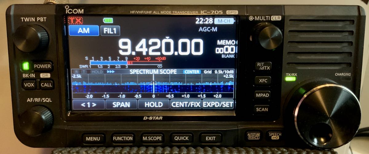
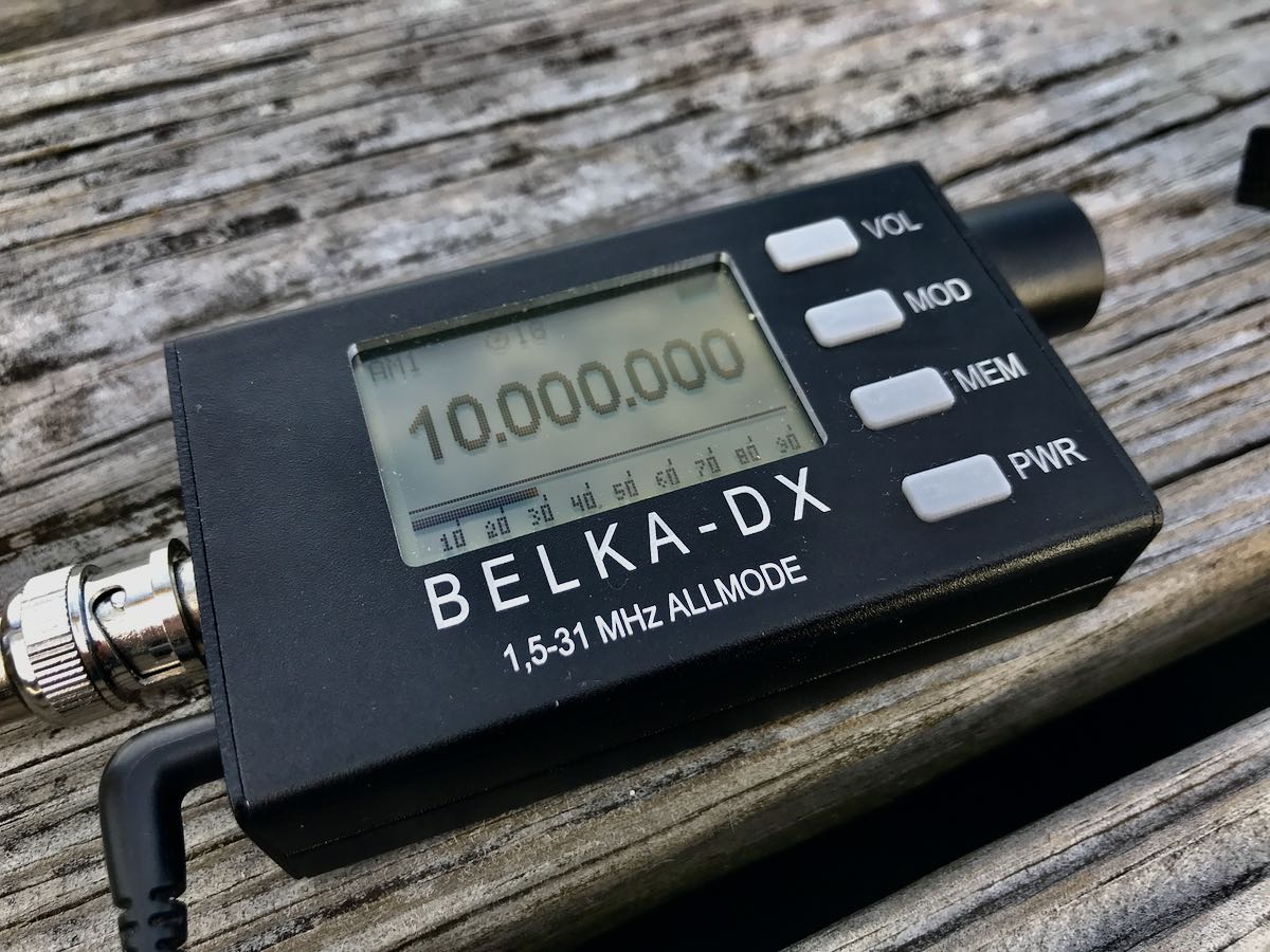
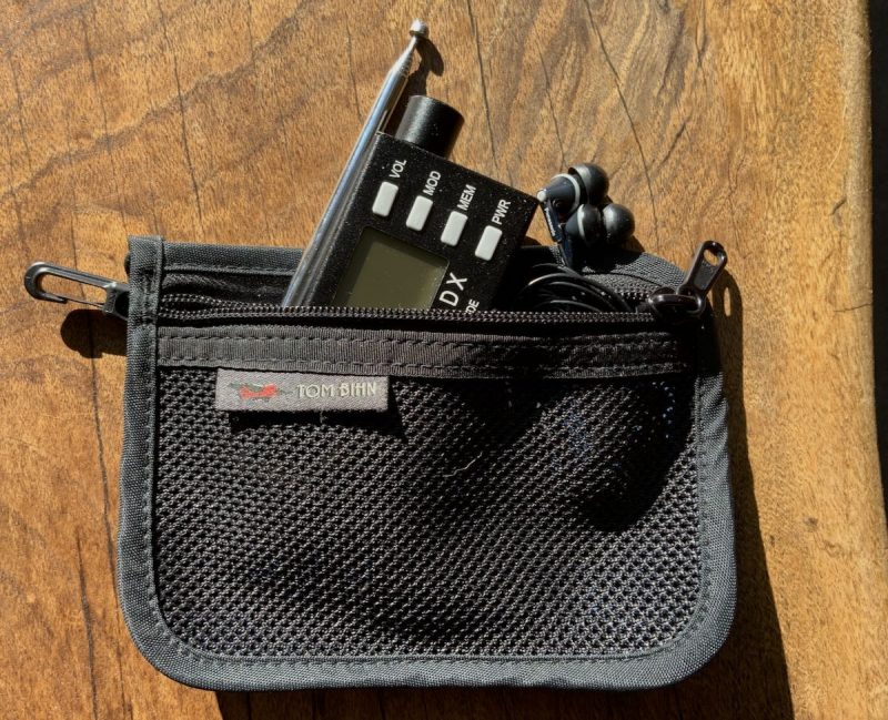
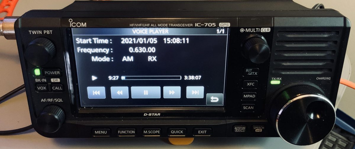
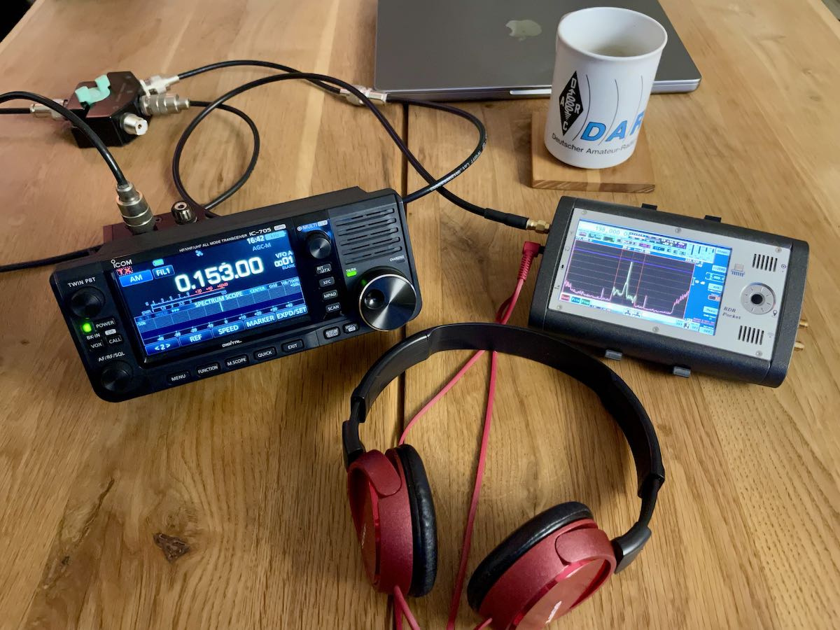 SWL with a Reuter Pocket and the Icom IC-705