Video: Pairing the AN-200 loop antenna with the Icom IC-705

Many thanks to SWLing Post contributor, Dennis Dura, who shares the following video featuring the Tecsun AN-200 on the Waters & Stanton YouTube channel:

I told so many over the years that I honestly think the AN200 is one of the most useful and effective mediumwave antennas you can purchase. It’s portable and it pairs so easily with most any radio.

Retailers:

Radio Waves: Arecibo Failure Caught on Video, Heathkit Employee Reminisces, Radio at 100 Series, and FCC to Require Email on Applications

Arecibo Observatory’s 305-meter telescope in November 2020 (Credit: University of Central Florida)

Radio Waves:  Stories Making Waves in the World of Radio

Because I keep my ear to the waves, as well as receive many tips from others who do the same, I find myself privy to radio-related stories that might interest SWLing Post readers.  To that end: Welcome to the SWLing Post’s Radio Waves, a collection of links to interesting stories making waves in the world of radio. Enjoy!

Many thanks to SWLing Post contributors Ned Wharton, Pete Eaton, Zack Schindler, and Dave Zantow for the following tips:


NSF releases footage from the moment Arecibo’s cables failed (ARS Technica)

Today, the National Science Foundation released video taken at the moment the Arecibo Radio Observatory’s cables failed, allowing its massive instrument platform to crash into the dish below. In describing the videos, the NSF also talked a bit about the monitoring program that had put the cameras in place, ideas it had been pursuing for stabilizing the structure pre-collapse, and prospects for building something new at the site.

A quick recap of the collapse: the Arecibo dish was designed to reflect incoming radio radiation to collectors that hung from a massive, 900-ton instrument package that was suspended above it. The suspension system was supported by three reinforced concrete towers that held cables that were anchored farther from the dish, looped over the towers, and then continued on to the platform itself. Failure of these cables eventually led to the platform dropping into the dish below it.

[…]The video of that collapse comes from a monitoring system put in place in the wake of the cable failures. Due to the danger of further cable breaks, the NSF had instituted no-go zones around each of the three towers that supported the cables. With no personnel allowed to get close enough to inspect the cables, the staff started monitoring them using daily drone flights, one of which was in progress during the collapse. In addition, a video camera was installed on top of the visitor’s center, which had a clear view of the instrument platform and one of the support towers.

Continue reading full article.

Heathkit: An Employee’s Look Back (Electronic Design)

Lessons of a successful electronic business—an interview with Chas Gilmore, former Heath executive.

For those of you who do not know or remember, Heath Company was the largest kit company in the world. Heath designed and put practically every type of electronic product into kit form. Its products, called Heathkits, were exceptionally popular and many are still in use today.

Over the years, Electronic Design has published many Heathkit-related articles and blogs. Recently, I had a chance to talk with Chas Gilmore, who was a Heath executive. For those of you who fondly remember Heathkit and miss its products, here’s a look back at this amazing company and the lessons it offers.

Chas, what was your affiliation with Heath?

A recent physics graduate, I joined Heath in 1966 as an engineer in the Scientific Instruments department. This was a new group designing laboratory instruments supporting the Malmstadt/Enke, Electronics for Scientists program. The kit business was making great strides.

The audio department was about to introduce the AR-15 FM receiver/amplifier. It had rave reviews, putting Heath in the top tier of the Audio/HiFi market. At the same time, the Ham (amateur radio) department was updating the phenomenally successful SB-line of an HF SSB receiver, transmitter, and transceiver, and modernizing the popular $99 single-band SSB transceiver line[]

Radio at 100 & Roots of Radio Series (Radio World)

Zack writes:

Found this interesting series at Radioworld called “Radio at 100”. It is 29 different articles about the history of broadcasting in the USA. A lot of your readers might enjoy these;
https://www.radioworld.com/tag/radio-at-100

Another great series at Radioworld that your readers might be interested in “Roots of Radio”:

https://www.radioworld.com/columns-and-views/roots-of-radio

ARLB038 FCC to Require Email Addresses on Applications (ARRL Bulletin 38 ARLB038)

Amateur radio licensees and candidates will have to provide the FCC with an email address on applications, effective sometime in mid-2021.

If no email address is included, the FCC may dismiss the application as defective.

The FCC is fully transitioning to electronic correspondence and will no longer print or provide wireless licensees with hard-copy authorizations or registrations by mail.

A Report and Order (R&O) on “Completing the Transition to Electronic Filing, Licenses and Authorizations, and Correspondence in the Wireless Radio Services” in WT Docket 19-212 was adopted on September 16. The new rules will go into effect 6 months after publication in the Federal Register, which hasn’t happened yet, but the FCC is already strongly encouraging applicants to provide an email address.

When an email address is provided, licensees will receive an official electronic copy of their licenses when the application is granted.

The Report and Order can be found in PDF format online at, https://www.fcc.gov/document/fcc-adopts-electronic-licensing-report-and-order

Under Section 97.21 of the new rules, a person holding a valid amateur station license “must apply to the FCC for a modification of the license grant as necessary to show the correct mailing and email address, licensee name, club name, license trustee name, or license
custodian name.” For a club or military recreation station license, the application must be presented in document form to a club station call sign administrator who must submit the information to the FCC in an electronic batch file.

Under new Section 97.23, each license will have to show the grantee’s correct name, mailing address, and email address. “The email address must be an address where the grantee can receive electronic correspondence,” the amended rule will state. “Revocation of the station license or suspension of the operator license may result when correspondence from the FCC is returned as undeliverable because the grantee failed to provide the correct email address.”
NNNN
/EX[]


Do you enjoy the SWLing Post?

Please consider supporting us via Patreon or our Coffee Fund!

Your support makes articles like this one possible. Thank you!

How to Build a Simple Linear-Loaded Dipole for Low-Noise Shortwave Radio Listening

Many thanks to SWLing Post contributor and RX antenna guru, Grayhat, for another excellent guest post focusing on compact, low-profile urban antennas:


A linear loaded dipole for the SWL

by Grayhat

What follows is the description of an antenna which may allow to obtain good performances even in limited space, the antenna which I’m about to describe is a “linearl loaded dipole”(LLD) which some call the “cobra” antenna due to the “snaking” of its wires
The arms of the antenna are built using 3-conductors wire (which may be flat or round) and the 3 conductors are connected this way:

That is, connected “in series”, this means that, the electrical length of the antenna will be three times its physical one; this does NOT mean that the antenna will perform like a single wire of the same (total) length, yet it allows to “virtually” make it longer, which in turn gives it good performance even with relatively short sizes. Plus, the distributed inductance/capacitance between the wires not only gives it a number of “sub” resonance points, but also helps keeping the noise down (in my experience below the noise you’d expect from a regular dipole).  At the same time it offers better performances than what one may expect from a “coil loaded” dipole. Plus, building it is easy and cheap and the antenna will fit into even (relatively) limited spaces (a balcony, a small yard and so on…).

Interested–? If so, read on and let me start by showing my (short – 9mt total) LLD installed on a balcony:

Here it is in all its “glory”–well, not exactly–I fiddled with it lately since I’m considering some mods so the tape isn’t correctly stuck and it has been raised and lowered quite some times, but in any case that’s it.

Bill of Materials

Here’s what you’ll need to build it (the links are just indicative, you may pick different stuff or buy it locally or elsewhere).

  • Some length of 3-conductors electrical wire which will fit your available space (pick it a bit longer to stay on the safe side), it may be flat or round, in my case I used the round type since it was easily available and cheap: https://amzn.to/3g2eZX3
  • A NooElec V2 9:1 BalUn–or, if you prefer you may try winding your own and trying other ratios. I tested some homebuilt 1:1, 1:4 and 1:6 and found that the tiny and cheap NooElec was the best fitting one): https://amzn.to/3fNnvce
  • A small weatherproof box to host the BalUn: https://amzn.to/33vjZy3
  • A center support which may be bought or built. In the latter case, a piece of PCV pipe with some holes to hold the wires should suffice. In my case I picked this one (can’t find it on amazon.com outside of Italy): https://www.amazon.it/gp/product/B07NKCYT5Z
  • A pair of SMA to BNC adapters: https://amzn.to/37krHwj
  • A run of RG-58 coax with BNC connectors: https://amzn.to/2JckHcR

Plus some additional bits and pieces like some rope to hang the antenna, some nylon cable ties, a bit of insulated wire, duct tape and some tools. Notice that the above list can be shortened if you already have some of the needed stuff and this, in turn will lower (the already low) cost of the antenna.

Putting the pieces together

Ok, let’s move on to the build phase. The first thing to do will be measuring your available space to find out how much wire we’ll be able to put on the air; in doing so, consider that (as in my case), the antenna could be mounted in “inverted Vee” configuration which will allow to fit the antenna even in limited space.

In any case, after measuring the available space, let’s subtract at least 1m (50cm at each end) to avoid placing the antenna ends too near to the supports. Also, if in “inverted Vee” config, we’ll need to subtract another 50cm to keep the feedpoint (center/box) away from the central support.

Once we’ve measured, we may start by cutting two equal lengths of 3-conductor wire. Next, we’ll remove a bit of the external sleeve to expose the three conductors and then we’ll remove the insulator from the ends of the three exposed wire (and repeat this at the other end of the cable and for both arms).

The resulting ends of each arm should look somewhat like in the example image below

Now we’ll need to connect the wires in series. We’ll pick one of the cables which will be the two arms of our antenna and, assuming we have the same colors as in the above image, we’ll connect the green and white together at one end and the black and green together at the other end. Repeat the same operation for the second arm and the cables will be ready.

Now, to have a reference, let’s assume that the ends of each arm with the black “free” (not connected) wire will go to the center of our dipole.

Leave the two arms alone for a moment, and let’s install the balun inside the waterproof box. To do so, we’ll start by cutting a (small) hole through the single rubber cap found at one side of the box, then insert the cap reversed, so that it will protrude to the inside of the box and not to the outside. Slide the balun SMA connector through the hole so that it will protrude outside the box.

Now use a marker to mark the balun position and remove the balun from the box. Pick a piece of wood/plastic or other insulating material, cut it to size (refer to marking and to balun size) and drill four holes matching the one found on the balun board. Slide four screws through the holes and lock them with nuts, the screws should be long enough to extrude for some mm. Now insert the balun in the screws using the holes present on the balun board and lock it with nuts (be gentle to avoid damaging the balun). At this point, add some “superglue” to the bottom of the support we just built, slide the balun SMA connector through the rubber cap hole we already practiced, and glue the support to the bottom of the waterproof box.  Wait for the glue to dry.

Just to give you a better idea, see the photo above. That’s a photo of the early assembly of my balun. Later on, I rebuilt it as described above (but took no pics!), the image should help you understanding how it’s seated inside the box–by the way in our case it will be locked by the screws to the plastic support we glued to the box.

While waiting for the glue to dry, we may work on the dipole centerpiece.

If you bought one like I did, connecting the arm “black” (see above) wires should be pretty straightforward. If instead you choose to use a PVC pipe you’ll have to drill some holes to pass and lock the wire so that the strain will be supported by the pipe and not by the wire going to the balun box. In either case, connect a pair of short runs of insulated wire to the end (black) wire coming from each end. Those wires should be long enough to reach the balun wire terminal block inside the box.

Assuming the glue dried, it’s time to complete the feedpoint connection.

Bring the two wires coming from the centerpoint inside the waterproof box. Pick one of the wire terminal blocks which came with the balun (the “L” shaped one should be a good choice) and connect the wires to it. Then, slide the block in place until it locks firmly. After doing so, close the box and screw the SMA-BNC adapter onto the SMA connector coming from the balun. Our centerpiece and arms will now be ready, and will be time to put our antenna up!

I’ll skip the instructions about holding the arm ends and the centerpiece up, since I believe it should be pretty straightforward. Just ensure to put the antenna as high as possible and, if you have room make the arms as long as possible. In my case, due to my (self-imposed) limitations, the antenna was installed on a balcony. The arms have a length of about 3.5m each and the feedpoint (in the image above) sits at about 9m off the ground.

The more acute readers probably noticed those “blobs” on the coax, they are snap-on ferrite chokes I added to the coax (there are more of them at the rx end) to help tame common mode noise. I omitted them from the “BoM” since they may be added later on.

Anyhow, now that you have your LLD up it will be time to give it a test! In my case, I decided to start by running an FT8 session to see what the antenna could pick up during 8 hours, and the result, on the 20 meters band, is shown on the following map (click to enlarge):

Later, that same antenna allowed me to pick up signals from the Neumayer station in Antarctica–not bad, I think!

Some final notes

While running my “balcony experiment”, I built and tested several antennas, including a vanilla “randomwire”, a dipole, and a T2FD.

Compared to those, the LLD offers much less noise and better reception on a wide frequency range. By the way, it won’t perform miracles, but it’s serving me well on the LW band, on most ham bands, and even up to the Aircraft bands–indeed, was able to pick up several conversations between aircraft and ground air traffic control.

All I can suggest is that given a linear-loaded dipole is so simple, quite cheap, and may fit many locations, why don’t you give it a spin–?  🙂

A little offline and on-radio time!

For the next week or so, I’m going to have limited Internet service, but lots of radio time. I’m looking forward to it!

There shouldn’t be an interruption here on the SWLing Post, but I will not have a lot of time to reply to questions via email. Feel free to continue sending your tips, articles, and stories, but if you have in-depth questions, it could take me a couple or more weeks to get back to you as I’m pretty sure my email will stack up during this time.

It’s ironic, but this crazy “Social DXing” year has provided me the opportunity to review and evaluate more gear than I ever have in one calendar year. On the flip side, I’ve been so busy doing evaluations that I’ve had less time to enjoy pure SWLing fun. I’m looking forward to fixing that this week!

If you have a radio related question, I’d encourage you to post it in the comments section of a related post (or even this post). We’ve an active community of radio enthusiasts here who are incredibly helpful.

Cheers & Happy Listening!

Thomas

David shares a recording of the RTE longwave interval signal

Many thanks to SWLing Post contributor, David Shannon, who writes:

Hi Thomas

A little treat for my fellow readers of your blog (is that the right word?). The RTE interval signal, a rendition of O’Donnell Abú (“O’Donnell Forever”), that is played at 0529 daily, apart from the weekend when it’s played at 0629 (even interval signals need a lie in) and received on longwave here in Scotland.

I know that longwave broadcasting is a very European thing with the exception of the likes of Mongolia (holy grail stuff for me) but it’s where my fascination for the bands started way back in 1978/9.

Sláinte mhaith gach duine
(Irish Gaelic for good health everyone)

That’s a beautiful interval signal, David. Thank you so much for sharing it with your fellow Post readers! There are few things in this world that make me feel more nostalgic than an off-air recording of an interval signal. Go Raibh Maith Agat!

FTIOM & UBMP, December 6-12, 2020

From the Isle of Music, December 6-12:
This week, special guest Toni Basanta returns to share music from Expreso Rítmico and Grupo Los Yoyi, two popular dance bands in Cuba in the 1970-1980s, with us.
The broadcasts take place:
1. For Eastern Europe but audible well beyond the target area in most of the Eastern Hemisphere (including parts of East Asia and Oceania) with 100Kw, Sunday 1500-1600 UTC on SpaceLine, 9400 KHz, from Sofia, Bulgaria (1800-1900 MSK)
If you don’t have a shortwave radio or are out of range, you can listen live to an uplink from a listening radio in the Netherlands during the broadcast at
http://websdr.ewi.utwente.nl:8901/?tune=9400am
2. For the Americas and parts of Europe, Tuesday 0100-0200 on WBCQ, 7490 kHz from Monticello, ME, USA (Monday 8-9PM EST in the US).
If you don’t have a shortwave or are out of range, you can listen to a live stream from the WBCQ website here: http://splatterbox.us/wbcq1
3 & 4. For Europe and sometimes beyond, Tuesday 1900-2000 UTC and Saturday 1300-1400 UTC on Channel 292, 6070 kHz from Rohrbach, Germany.
If you don’t have a shortwave radio or are out of range, you can listen live to uplinks from various websdrs in Europe.
Our Facebook page is https://www.facebook.com/fromtheisleofmusic/
Our V-Kontakte page is https://vk.com/fromtheisleofmusic
Our Patreon page is https://www.patreon.com/tilford

Uncle Bill’s Melting Pot, December 6-12:
In episode 194, we listen to music from Norway.
The transmissions take place:
1.Sunday 2300-0000 (6:00PM -7:00PM EST) on WBCQ The Planet 7490 kHz from the US to the Americas and parts of Europe
If you don’t have a shortwave or are out of range, you can listen to a live stream from the WBCQ website here: http://splatterbox.us/wbcq1
2. Tuesday 2000-2100 UTC on Channel 292, 6070 kHz from Rohrbach, Germany for Europe.
3. Saturday 0800-0900 UTC on Channel 292, 9670 kHz from Rohrbach, Germany for Europe.
Our Facebook page is https://www.facebook.com/UncleBillsMeltingPot/
Our V-Kontakte page is https://vk.com/fromtheisleofmusic
Our Patreon page is https://www.patreon.com/tilford

Review Notes: Xiegu GSOC Firmware updated to version 1.1–still a number of issues

For those of you who have been asking about the new Xiegu GSOC controller, I just updated my unit with the latest firmware (version 1.1).

Firmware notes show that it addresses the following items:

Xiegu GSOC FW V1.1
1. Solved the CW sidetone delay problem
2. Solved the problem of unstable system and occasional crash
3. Added RTTY modem
4. Added CW decoder
5. Added SWR scanner
6. Added FFT/Waterfall level adjustment
7. Added FFT line/fill color mixer

The list above was copied directly from the version notes.

I’m currently evaluating the GSOC/G90 pair which were kindly sent to me on loan by Radioddity. I upgraded the GSOC firmware to v1.1 this weekend.

What follows are some of my evaluation notes an observations after performing the upgrade.

Updating firmware

Updating the GSOC firmware is a pretty straight-forward process.

First you must download the GSOC firmware package (about 330 MB!) which includes a disk image and application to flash the image to a MicroSD card.

Yes, you’ll need a dedicated MicroSD card to upgrade the GSOC firmware–meaning, you can’t simply use a MicroSD card with data on it you’d like to keep because the process of flashing the ISO file also includes a full format with multiple partitions.

You’ll also need an SD Card reader/writer if your Windows PC doesn’t include one.

The included firmware application/tool makes it quite easy to flash a disk image on the MicroSD card.

After the MicroSD card has been prepared, simply turn off the GSOC, insert the MicroSD card on the left side of the GSOC, turn it back on and the GSOC will automatically boot from the MicroSD card and install the new OS/firmware.

Once the upgrade has completed, the GSOC will turn itself off and you must remove the MicroSD card.

If you want to restore the MicroSD card to one partition, you’ll need to perform another format and shrink the volumes.

CW sidetone latency (still issues)

After performing the upgrade, I hopped on the air and tried to make a few CW contacts since I noted in the version notes that the CW sidetone latency had been addressed. So far, my evaluation has pretty much been on hold because I’m unable to use CW mode with any sense of sending accuracy.

Unfortunately, I’m still finding that there’s still a bit of sidetone latency or keyer timing interfering with my ability to correctly send words and letters.

To my ear, it sounds like there’s much less latency in the sidetone audio now (compared with v1.0 which was a little insane) but I still struggle sending characters that end in a string of dits or dashes. For example, when I try to send a “D” the radio will often produce a “B” by adding one extra dit. Or if I try to send a “W” it might produce a “J”. I know something is a little bit off because I botched up two CW contacts with POTA stations yesterday as I tried to send my own callsign correctly.  And “73” was even problematic.

I’m guessing that there may still be a bit of audio lag between the G90 body (where the CW key is plugged in) and the GSOC (where the sidetone audio comes out). At the end of the day, the keying information must be sent to the GSOC from the G90 transceiver body and I assume the processor on the G90 is causing a bit of audio latency. Hopefully, Xiegu can sort this out. It’s a serious issue for anyone who wants to operate CW with the GSOC.

If you own the GSOC and operate CW, I’d love your comments and feedback.

Other updates

I tried using the CW decoder yesterday via the “Modem” menu and had limited success decoding a CW rag chew.

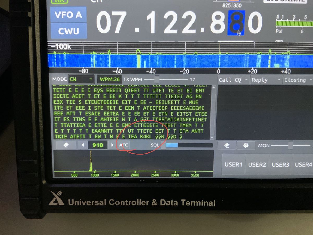
My markup in red: You can see at the very end of this conversation, it decoded the call sign, but interpreted “TU” as “TEA”

The decoder seemed to adjust the WPM rate automatically at one point, but as you can see in the image above, almost every dit was interpreted as an “E” and every dash a “T”. I must assume I don’t have it configured properly, but I don’t have an operator’s manual for reference and instruction.  I’ve also tried RTTY decoding, but haven’t been successful so far–I’m pretty sure this is also because I haven’t configured it properly.
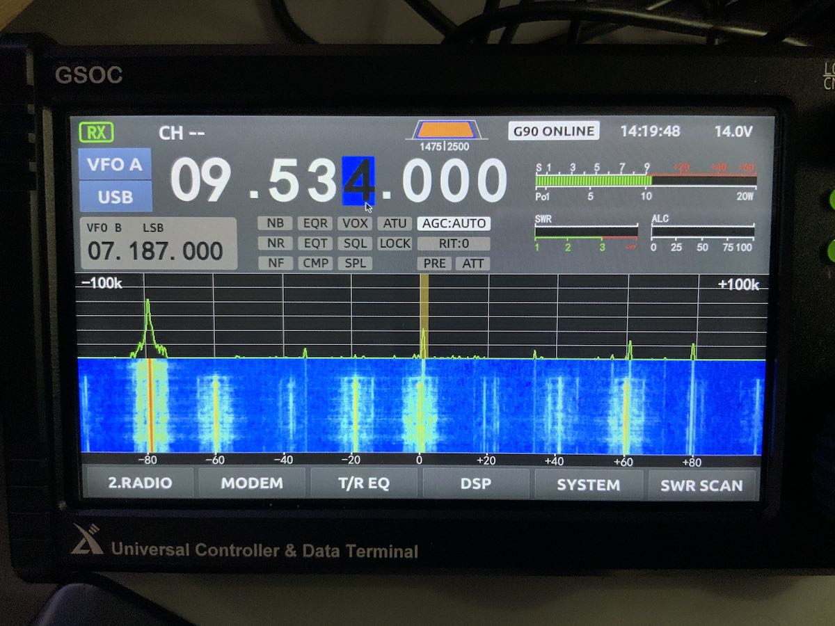
SWR Scanner

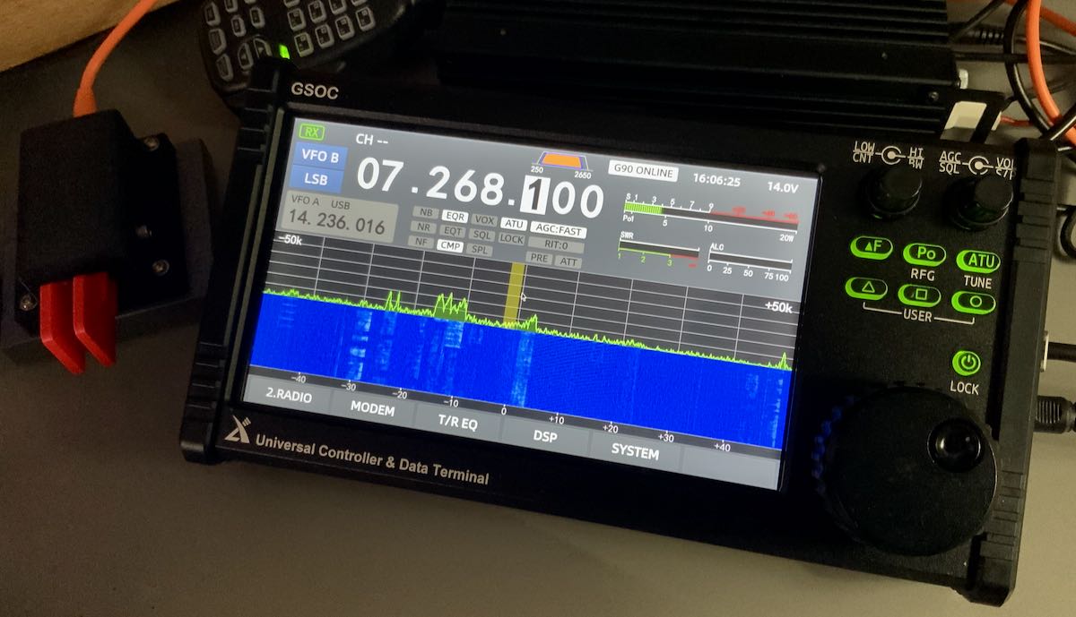
I tested the new SWR scanner and it seems to work quite well, plotting SWR across a given frequency range. I did note, however, that it doesn’t seem to confine itself to the ham bands at all. It does inject a signal as it scans (I read 1.5 to 2 watts on my CN-801 meter).

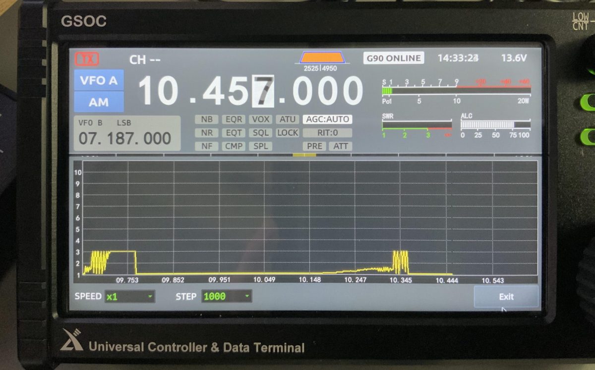
I discovered out-of-band scanning when I took the photo above while trying to do a scan of the 30 meter band. It started around 9.6 MHz–well into the 31M broadcast band where it shouldn’t be transmitting. Xiegu needs to limit transmitted signal to the ham bands.

Memory Keying

I had hoped Voice Memory Keying would be added along with TX/RX recording. I do believe this will eventually be included in a future update. It appears via the “Modem” menu that CW Memory Keying has been added, but I can’t sort out how to make it work (again, a operation manual would be quite handy).

Audio recording

I had hoped transmit and received audio recording would be added in this firmware update; I understand this will eventually be added.

Combined current drain

As I mentioned in a previous GSOC update, the GSOC controller and G90 transceiver both need a 12V power source–indeed, each has a dedicated power port. The GSOC does not derive power from the G90.

I was originally told that the G90 and GSOC both pull about .60 amps in receive which would total 1.2 amps combined. My Hardened Power Systems QRP Ranger battery pack displays voltage and current; it’s not a lab-grade measurement device, but it’s pretty accurate. When I operate the GSOC and G90 at a moderate volume levels in receive, it appears to draw 0.95 to 0.97 amps–basically, 1 amp.

At home on a power supply, this is inconsequential, but in the field you’d need to keep this in mind when choosing a battery. It’s on par with a number of 100 watt transceivers.

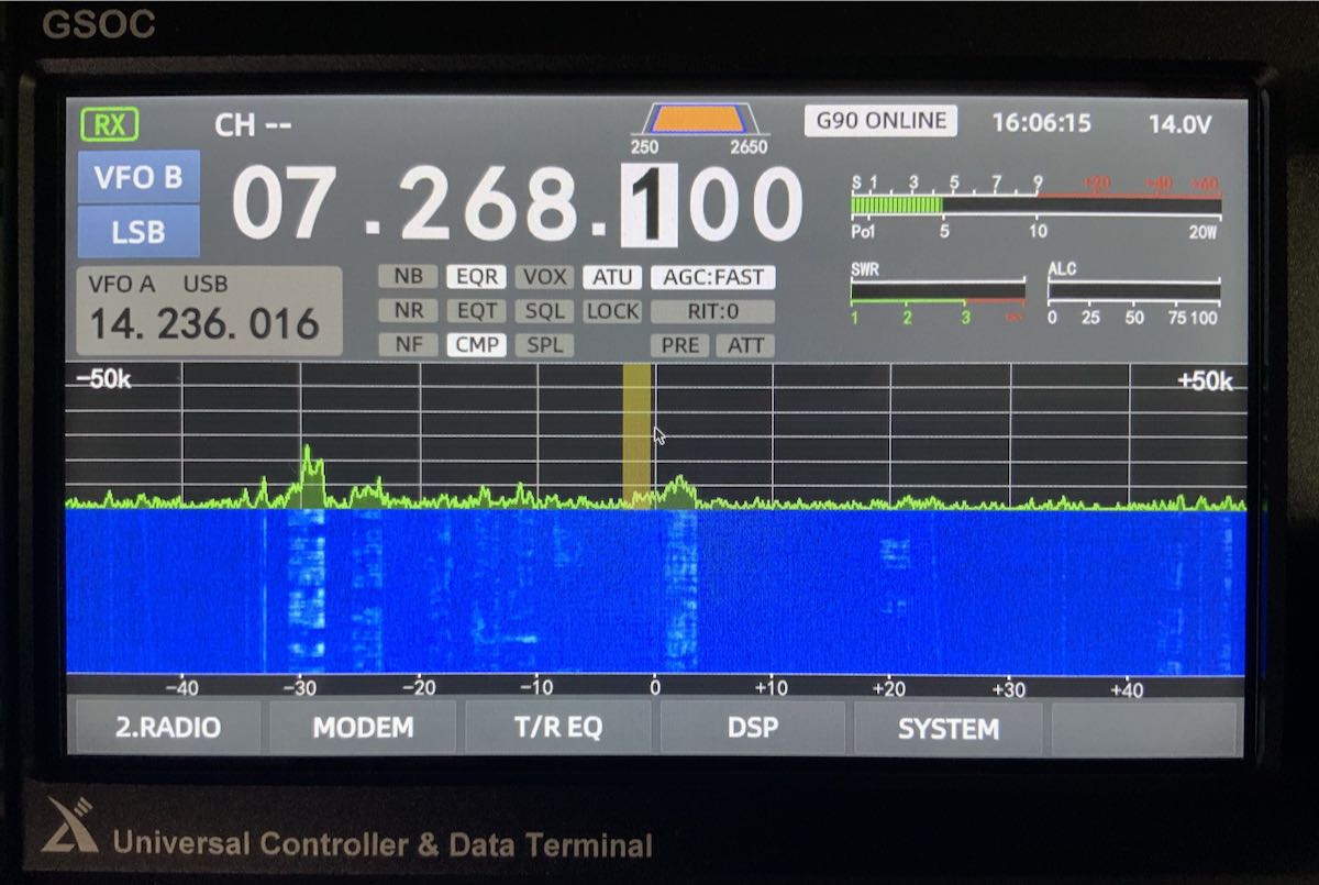
Spectrum display images

I’m still finding images on the GSOC display that are not present in the received audio. I mentioned this in my initial overview and it doesn’t seem the firmware update addressed this.

I can only assume the spectrum imaging might be due to the I/Q input being too “hot” coming from the G90 via the shielded audio patchcord. Perhaps there’s a function to manually lower the I/Q gain, but I haven’t found that yet.

Spectrum images are most noticeable on the 31 meter band, but found them on the 20 meter ham band as well.

Here are two screen shots that show how images appear when a nearby signal overwhelms the GSOC:

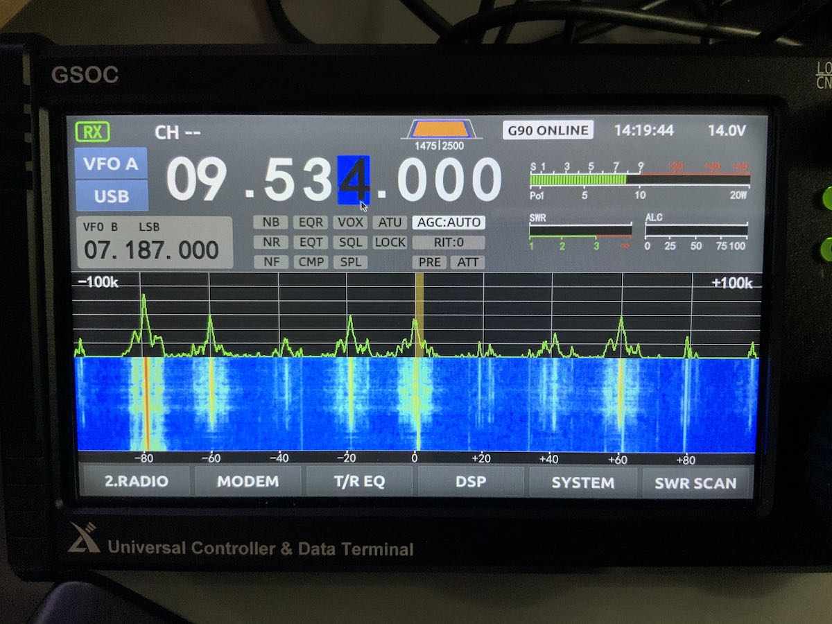
Images are not present all of the time, only when a strong signal intrudes.

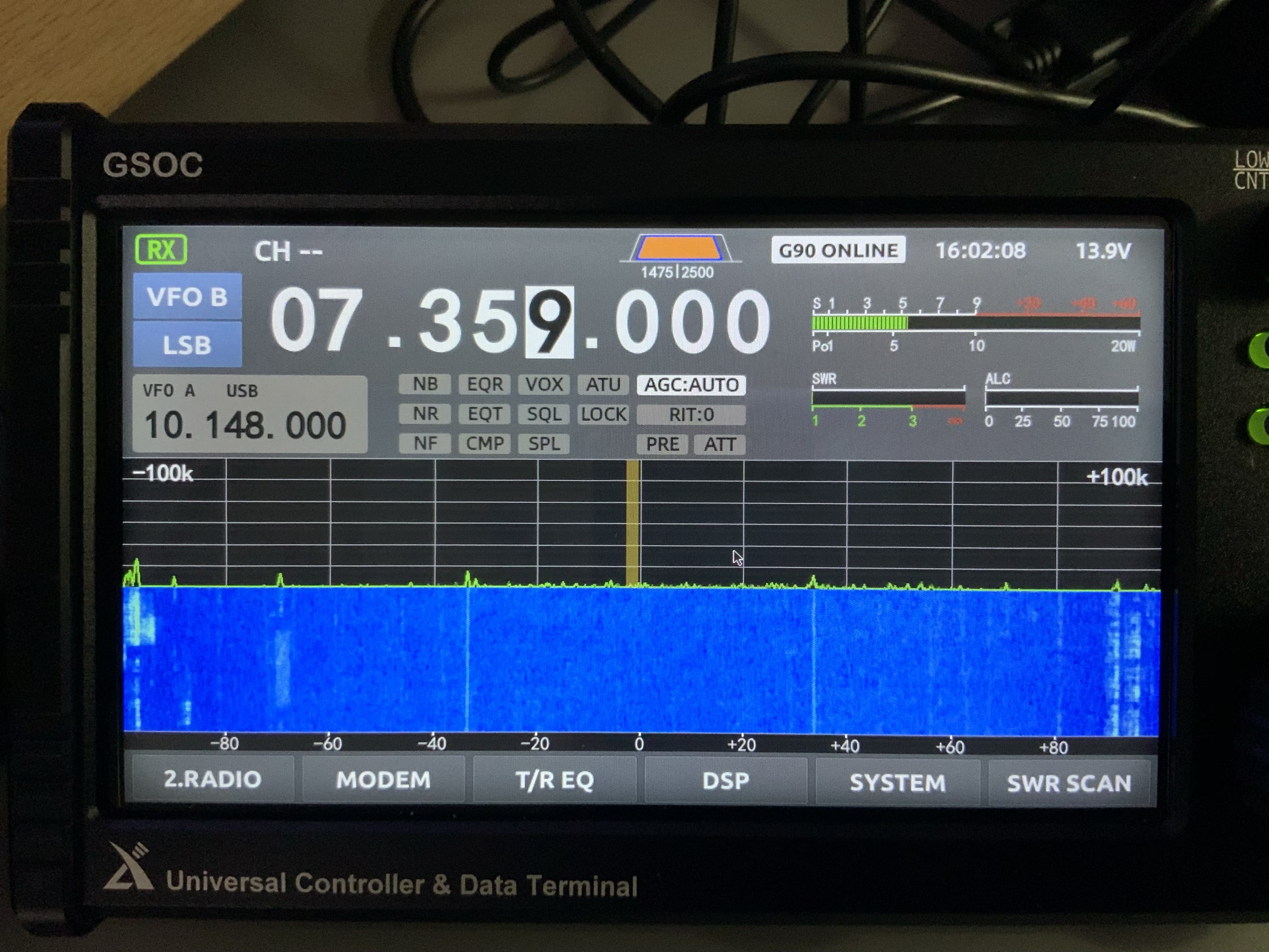
Ever-present noise and spurs in portions of spectrum

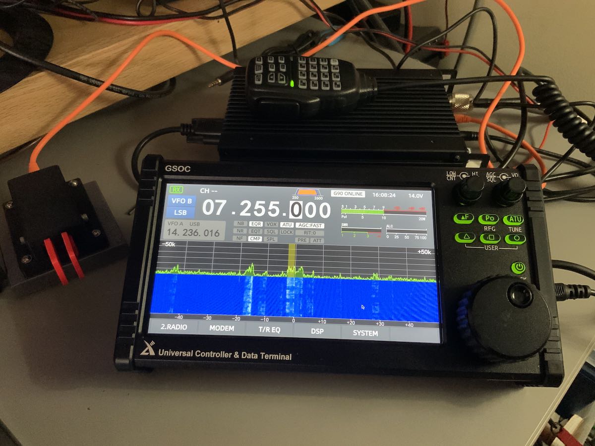
Perhaps this is related to the issue above, but there are some spurs on the spectrum display that seem to be present whether the G90/GSOC is hooked up to an antenna or dummy load.

Here’s a photo of the GSOC hooked up to an antenna:

And to a dummy load:

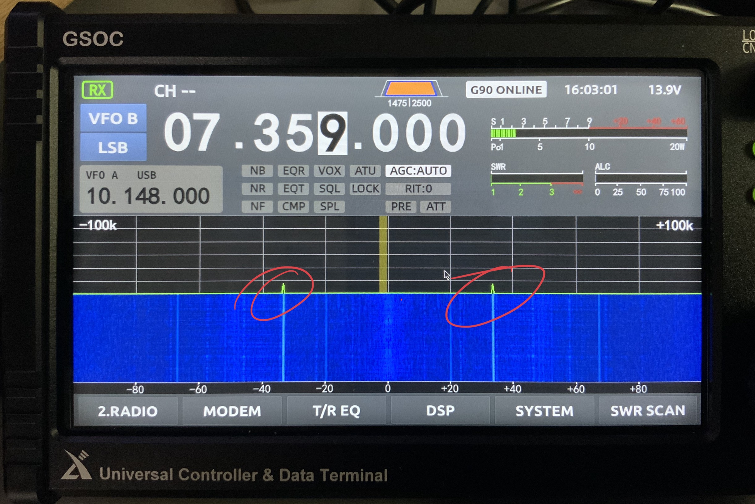
I’ve highlighted the spurs in red and as you can see, the intensity is stronger without an antenna thus I’m guessing this is internally-generated. The spurs do not move on the display as you change frequency.

Other notes

Again, I feel like the GSOC firmware isn’t mature and I can’t yet recommend purchasing it. I feel like Xiegu have rushed this unit to market.

I know that, over time, more features will be added and Xiegu certainly has a track record of following up.

When I evaluate a product, I keep a list of notes that I send to the manufacturer and to keep for my own reference. In Alpha and/or Beta testing, I’d share this info only with the manufacturer. Since the GSOC is a product that’s in production and widely available, however, I thought I’d share them here publicly:

  • GSOC volume control scale is 0 to 28. The difference between 0 (muted) to 1 seems to be the biggest increment. Volume 1 is actually a low to moderate volume level (i.e. a bit high).
  • Boot up time for the GSOC is 30 seconds
  • A keyboard and mouse or capacitive stylus are almost required for accurate operation. Many of the touch screen buttons are quite small and difficult to accurately engage with fingertip. The pointer seems to fall slightly below where fingertip makes contact on the screen.
  • Notch Filter seems to have no effect even after the v1.1 upgrade. There is no Auto Notch feature either.
  • I can’t seem to engage split operation even though there are A/B switchable VFOs and a “Split” button above the spectrum display. Using a keyboard and mouse doesn’t engage it either.
  • There are a number of announced features that I haven’t discovered including some WiFi and Bluetooth wireless functionality.
  • For field use, you must pack quite a bit of kit: the transceiver, the controller, CW key cable, microphone, serial cable, I/Q cable, G90 Power cable, and GSOC power cable. It would also be advisable to take a wireless keyboard and mouse especially if you plan to use any advanced functions like CW memory keying.
  • It doesn’t appear that you have CAT control of the GSOC which complicates digital operation. I believe many of us hoped the GSOC would make digital mode operation easier with the G90, but it hasn’t. Indeed, I assumed the GSOC would have an internal sound card for digi modes much like the Icom IC-7300 and IC-705. Use of VOX control is still  the best way to control transmit. I hope this can be upgraded else this would be a missed opportunity.
  • Since the v1.1 upgrade, the GSOC hasn’t crashed (it did frequently with the v1.0 firmware).
  • Not a pro or con, but I wish the AF Gain/Squelch was AF Gain/RF Gain like most HF transceivers. I’ve accidently engaged squelch twice which essentially muted audio. Pressing and holding the PO (Power Output) button opens the RG Gain control function).

The GSOC Universal Controller is an interesting accessory for the G90 and I’ve read comments from users that love the interface and added functionality.

If I’m being honest, I feel like I’m Beta testing the GSOC. I’ve yet to find a GSOC operation manual–this makes it very difficult to know if one has correctly configured the controller and engaged features/functions correctly. A quick start guide is included with the product, but it really only helps with connections and starting up the GSOC the first time. If you’re a GSOC early adopter, just be aware of this. Again, I’m pretty confident Xiegu will make refinements and include promised features in future firmware updates. I understand their software engineer closely monitors the GSOC discussion group as well. If you’re considering the purchase of a GSOC, I’d encourage you to join the GSOC group.

Questions? Comments?

As I said, I can’t recommend purchasing the GSOC controller yet. So much can change with firmware updates, however, I would encourage you to bookmark the tag GSOC to follow our updates here on the SWLing Post. I will update the GSOC controller each time a new firmware version is issued and until Radioddity asks for the loaner units to be returned. Again, many thanks to Radioddity for making this GSOC and G90 evaluation possible.

Feel free to comment with any questions you might have and I’ll do my best to answer them!