Tag Archives: Antennas

Build an SDR station and balcony antenna farm for less than 150 Euros

UPDATE 11 May 2020: We recently learned that the MSI.SDR software defined radio dongle in the following post and tutorial is a clone of the SDRplay RSP1 SDR. We did not realize this when the post was published. Grayhat had done research prior to purchase and believed it not to be a clone, but only using the same chipset as the RSP1 (hence the compatibility with SDRuno). We have confirmed that it is indeed a clone now via SDRplay (clear here to read more via the excellent RTL-SDR blog). What follows isn’t an SDR review. Indeed, Grahat’s post has little to do with the receiver and much, much more to do with building proper antennas! We’ve removed links to the MSI.SDR and would encourage you to invest in the excellent SDRplay RSP1a instead (click here to read our RSP1a review). Thank you for understanding!
Many thanks to SWLing Post contributor, Grayhat, who shares the following guest post. He lives in Italy and has been in lock-down since the beginning of the pandemic. He pitched the idea of building an entire SDR setup from scratch–receiver and antennas–for less than 150 Euros (roughly $163 USD). I thought it was a brilliant idea and I believe he thoroughly enjoyed the challenge of sourcing the components and building a mini antenna farm on his balcony while in quarantine:


From Zero to SDR

by Grayhat

What follows doesn’t pretend to be some kind of “definitive guide” or “last word”, on the contrary, it’s aimed at people who have little or no experience with SDR but want to try putting together a decent station without paying an arm and a leg.

The idea of writing this came to me after reading a number of messages and discussions on various online groups/forums, in a lot of cases, someone bought an SDR (usually the ones coming with a telescopic whip antenna), and after connecting it was expecting it “just to work” or, better said, pretending that the SDR connected to that whip (usually placed on a table right near the computer) could receive ANY POSSIBLE signal, including transmissions coming from the “dark side of the moon.” 🙂 Those folks got scared by the fact that the SDR “didn’t work” and decided to give up; now, this short “guide”  should allow anyone to setup what’s needed to have a working SDR

My self-imposed limitations for this project/experiment were the following:

  1. The whole setup shouldn’t cost more than 150 Euros so that, if after trying the SDR one doesn’t like it, (s)he won’t have paid $$$, otherwise, if (s)he decides to keep it, the resulting station will allow for further expansion/improvement
  2. The available space was considered to be that of an apartment, that is, no large field to put up huge wire antennas or to raise towers, the limit was the one of a balcony (in my home) that is 8 meters (max antenna length) by 3 meters (available height) by 2 meters (balcony width)
  3. The whole setup should be simple and straightforward, no need to solder components or to build special types of antennas
  4. Given the current Covid-19 sheltering, most components should be available online, while for others one may arrange with whatever is locally available (e.g. duct tape)

With the above limitations in mind, I took pencil, paper and rubber eraser (high-tech instruments, indeed) and started writing down a list of the needed stuff, after some writing, wiping and second thought, I came out with the following list, available on Amazon:

Bill of materials

The above includes all the needed stuff to put together a number of wire antennas (random wire, random dipole, loop…) the coax to connect the SDR, a balun to match the coax to the antenna and the accessory parts needed to put up the antenna. The selected SDR isn’t the common “RTL SDR” type, not that they don’t work, but their 8 bit ADC is far from being a good performer, so I decided to pick a different SDR which offers a 12 bits ADC and which also “presents itself” to the system as an SDRplay RSP1.

[Please note: we’ve since learned from SDRplay that the MSI.SDR is indeed a clone of the SDRplay RSP1. Here’s a post from the RTL-SDR blog confirming this. We recommend purchasing the RSP1a as a better alternative.]

Anyhow; all I can say is that after some tests, the MSI.SDR is a quite good unit and offers quite a lot of bangs for the buck, so I believe it may be a good unit for people willing to get their feet wet with SDRs

The above being said, here’s a pic of the MSI.SDR unit with the included stuff:
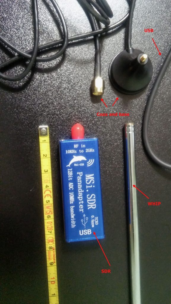
The unit is very small and the box has two connectors, an SMA for the antenna and a micro-USB (like the ones used in cellphones) for the USB cable which is used to both power and control it; the other bits are the telescopic whip antenna (around 98cm fully extended) with a magnetic base and a short run of coax, and the USB cable.

Once I got the SDR I decided to give the included whip antenna a try… well, to be clear, while it will allow you to pick up some strong local FM stations and maybe a bit else, it will only be useful to test if the SDR unit is working (before putting together our antenna), so don’t expect to receive much with that whip, yet… don’t throw it away, it may become useful (more later).

The other important piece is the BalUn. I picked a NooElec “Nine to One” v2, since I’ve used their v1 model and I’ve found it to work well, I decided to pick the newest model which has a better antenna wire connector.  The BalUn, which is in effect a so-called “transformer balun” is really small and the junction box I bought is much bigger, but it isn’t a problem. All in all, the box may host a preamplifier in the future, but for the moment it’s fine for the balun. The following pic shows the balun “installed” inside the junction box:
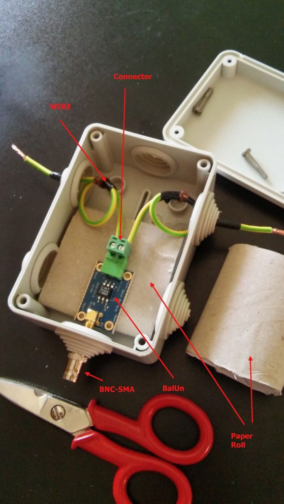
The scissors are there to give you an idea of the sizes; to put together the whole thing, I started by preparing two pieces of wire (the 2.5mm one),  made a turn with each wire and locked them with a nylon cable tier. Those turns will prevent the wire from sliding out and putting a strain on the balun connector.  I did that since I didn’t have plastic washers at hand, otherwise you may just slide two plastic washers (or proper diameter) over the wires and use two nylon tiers to lock them. In either case, the idea is that the “loops” or the washers won’t slide through the box holes and will support that (little bit of) strain caused by the wire connection.

Next, I stripped some of the insulation from the ends and connected the wires to one of the balun connectors (I chose the one in the pic since I believe it’s the most suitable for this setup), at that point I continued cutting the smaller “ring” of the box insulation caps (the two at top and the bottom one). Then I placed a piece of carboard roll (from a kitchen-paper roll) at the bottom to serve as a support (you can see it below the balun). At that point, I slid the balun SMA connector through the bottom hole and used the SMA to BNC adapter to hold it, done so I slid the two wires (connected to the green wire connector) through the side hole and then inserted the connector into the balun. I then placed the other piece of paper roll above the balun and closed the box with its cap. As a note, to properly close it, start by inserting the screw into the cap holes till end, so that they’ll extrude from the bottom, then place the cap over the box and tighten the screws–you may need to use some force to properly tighten it.

Notice that the wire shown in the pic are SHORT, later on I replaced them with longer wires (outside the box) to be able to better connect the balun box to the antenna, but the remainder of the build is the same.

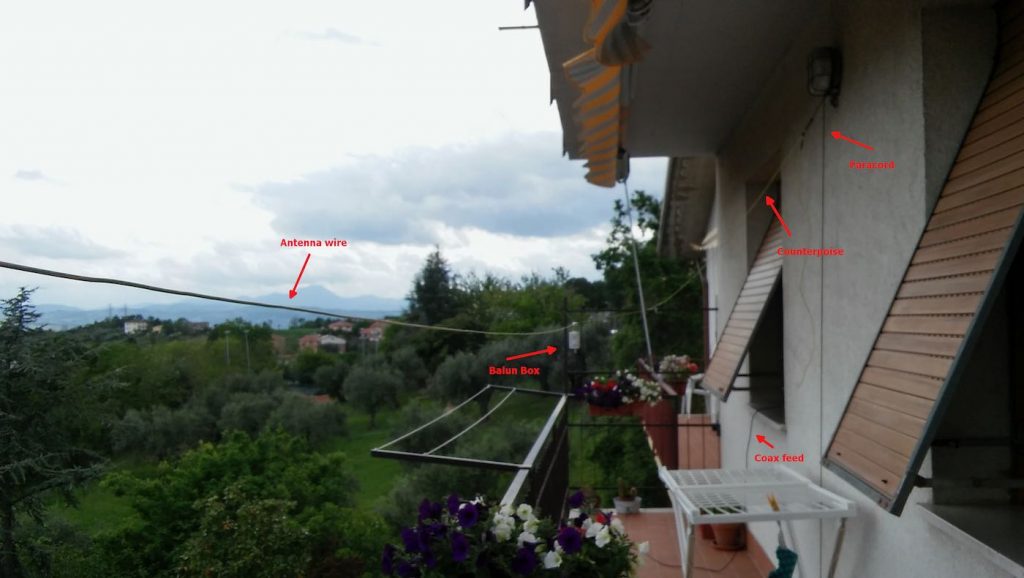
Now that I had my “balun box” ready, I measured the antenna wire and, using the paracord and some nylon tiers, I installed it. I also installed the “counterpoise” wire. For the latter, at first I tried just connecting the remainder of wire to the “gnd” of the balun, leaving the spool laying on the floor, but later on I decided to hang up the counterpoise and the final result was the following:

Click to enlarge

Not a work of art, but then since I was experimenting, I decided not to add PTFE and tape to allow me to quickly rearrange the antenna to run other configurations, yet, the whole setup worked quite well and stood fine to some wind and rain, the picture below shows the balun box with the antenna/counterpoise wires and the coax with the snap-on ferrite chokes.
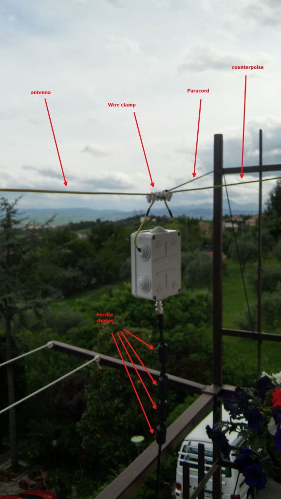
Click to enlarge

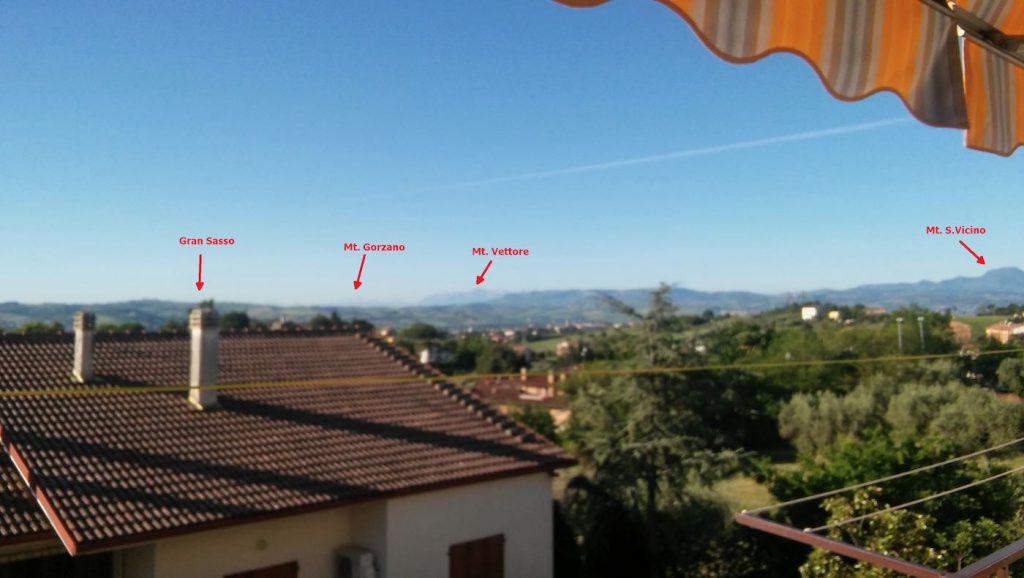
Notice that to avoid putting strain on the balun wires, I used a wire clamp I had in my junkbox–the clamp is then tied to the paracord using a nylon tier and the paracord holds the assembly and keeps the antenna wire in position. The ferrite chokes aren’t properly seated, and I’m planning to remove and re-place them, but for the moment they’re okay. The balcony faces to south/south-west so the antenna has a free horizon of about 270 degrees ranging from the Adriatic coast to the Appennines (Mt. S.Vicino can be seen behind the paracord)–not bad. Here’s another pic showing the horizon to West, just to give you an idea:
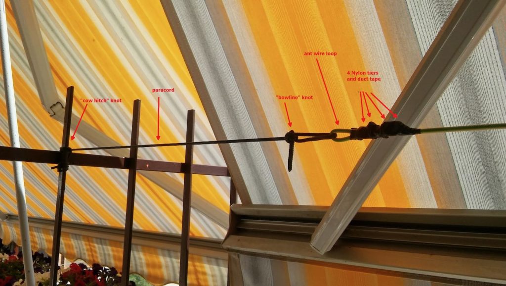
Getting back to the antenna installation, the other end of the antenna wire is tied to the opposite side of the balcony as shown below (let aside the tent/awning, I raise them when using the SDR, also, the bowline knot isn’t correct, I’ll need to tie that again):
The counterpoise instead is supported by a lamp I’ve on the terrace, here’s it’s setup:
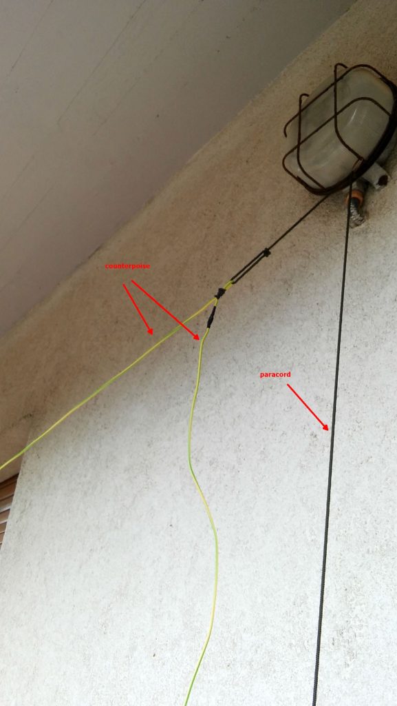
The “paracord” goes down to a plastic bottle filled with a water/chlorine mixture which serves to keep it in place. The remainder of the wire is just hanging down for about 1.5 meters (the counterpoise is shorter than the antenna wire, it’s about 2/3 of its length).

Ok, time to put the antenna and SDR to test, so I brought the coax inside home, connected the other SMA to BNC adapter to the SDR and connected the coax going to the antenna. Note that 15 meters of coax is enough for me, but if one wants a length of up to 25 mt, it won’t be a problem.

I already installed the SDR software, in my case since the unit identifies itself as an “SDR1” I downloaded the SDRPlay “SDRuno” software https://sdrplay.com/windl2.php and since I was at it I also downloaded the PDF manual https://www.sdrplay.com/downloads/ and the “CookBook” http://www.nn4f.com/SDRuno-cookbook.pdf and I heartly recommend reading and digesting them before starting the whole thing (while you wait for all the stuff to be delivered). An important note is that you MUST install the SDRuno software BEFORE connecting the SDR since that way, the SDRuno setup will install the proper drivers and you won’t have issues.

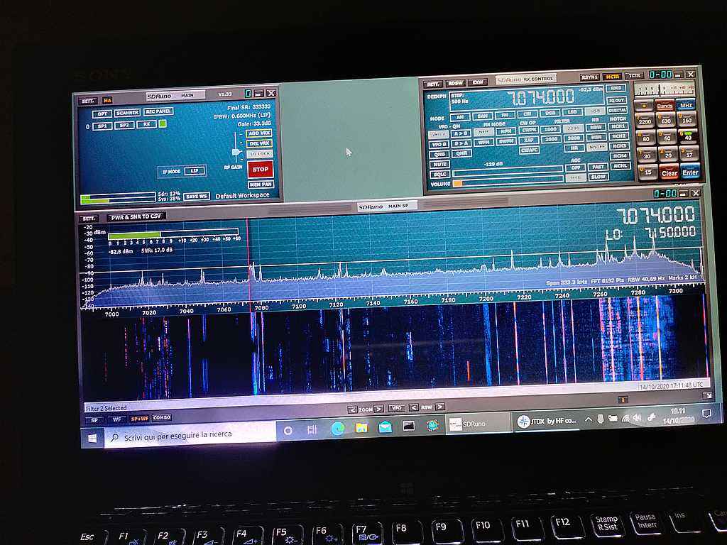
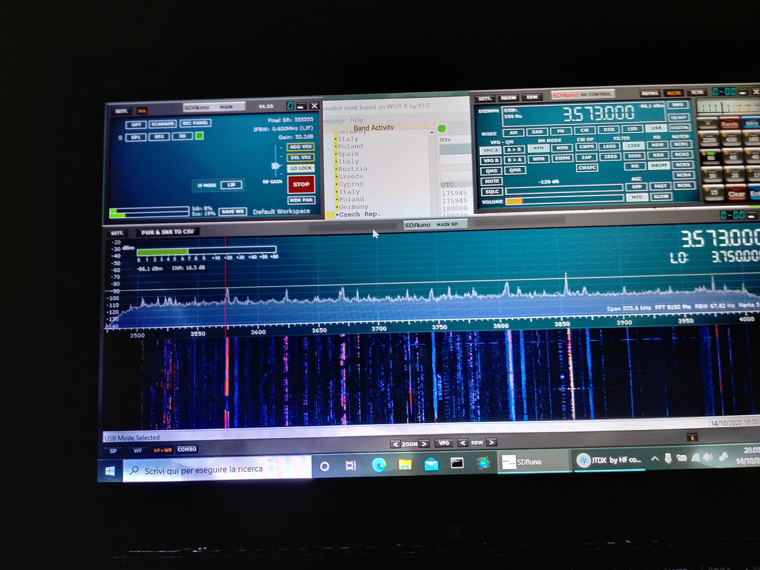
Anyhow, I connected the coax to the SDR and then it was time to fire up the whole thing and give it a spin; so I powered up the laptop (technically, a “transformable” laptop/tablet), started SDRuno, opened the “RX control” and “Main Spectrum” windows and then clicked the “play” button, clicked the “broadcast” band, and the “MW” one and got this:
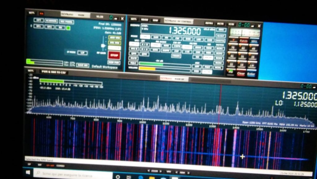
Not exceptional maybe, but not bad, either; in particular if one considers that it’s from a quite short piece of wire which isn’t exactly placed in an ideal position.
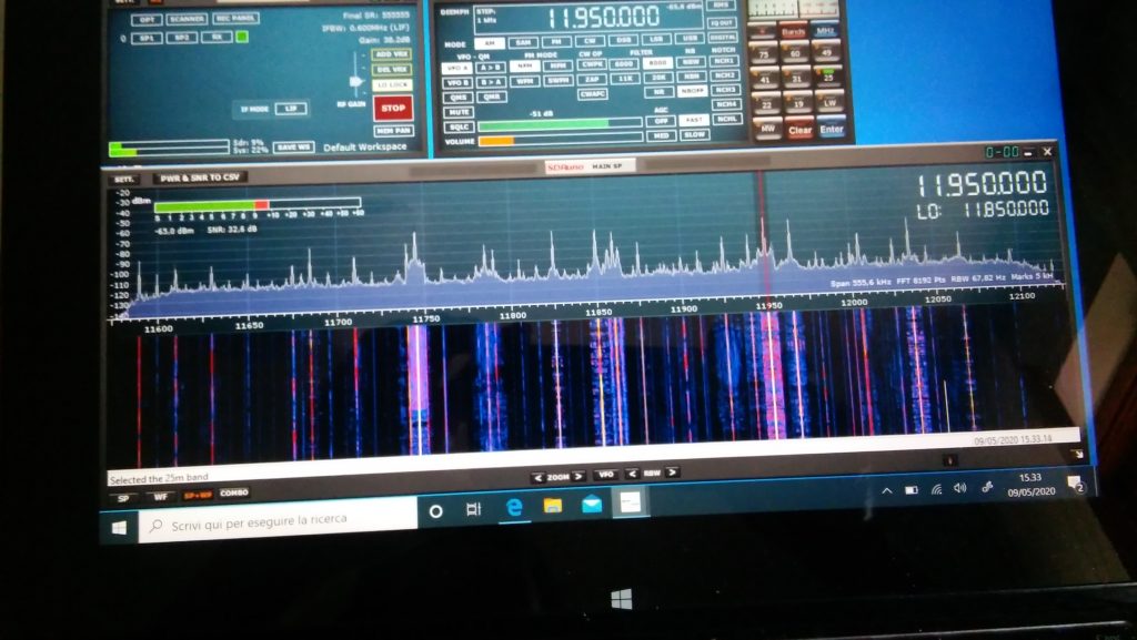
Deutsche Welle

So I went on and explored the bands a bit. On ham bands the SDR picked up signals from the whole mediterranean basin (Cyprus, Lebanon, Spain and then some) and from north too (Russia, Germany, Denmark); then depending on time, I was able to clearly receive broadcasts from China, South America, Africa and more ham QSOs from a lot of places.
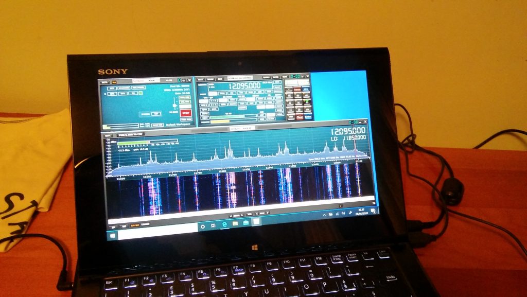
BBC Ascension Island 5/9+ and just a bit of QSB

I must admit I didn’ record the callsigns or stations identifiers (“guilty” your honor–!) but I was more focused on testing the SDR and antenna than running a “DX session” at any rate.  On the BCB bands I picked up WWV, BBC,  VoA, China Radio International, Radio Free Asia, Radio Romania and a bunch of others from Middle East, Asia, Africa and South America. While on the ham bands, I was able to pick up some quite interesting QSOs and then… well, I went hunting for higher frequencies signals!

I got Police, Ambulances, Air control…so even if that “piece of wire” isn’t optimized for VHF/UHF it seems to be working decently there too. By the way, when changing bands you may (and probably will) need to adjust the gain control, but that will be almost the only thing needed to pull in signals

At the end of the day, I can say that I’m quite pleased with the performance offered by this simple and cheap setup. For less than 150 euros you have everything you need, not just the SDR.

Sure, the setup may be improved, but then again you’ll have all of the basic parts, so you won’t need too much. For example, if you live in a really noisy environment, it would be a good idea to use a loop antenna. You would only need a “cross shaped” support (PVC pipes or wood will do). You could quickly put together the SRL (Small Receiving Loop) designed by Matt Roberts (KK5JY) http://www.kk5jy.net/rx-loop/ the balun will be the SAME (yes, no need to wind whatsoever!) so building it will just be a matter of assembling a cross shaped support for the wire (which we already have because it’s the same used for the wire antenna) and you’ll have it. While I already tried the SRL, I didn’t build one to test with this SDR, but I’ll probably do that as soon as SWMBO will start complaining about those “wires on the balcony.”

Also, at the beginning I wrote “more later” when writing about the telescopic whip included with the SDR. Here’s the idea–it requires soldering, so if you don’t want that, skip this: remove the adhesive sheet on the bottom of the antenna base to expose the bottom cap and then remove (extract) the bottom cap. You’ll see a magnetic ring and a “bell shaped” piece of metal (the “ground” for the whip). In the middle of the “bell” there will be the antenna connector which is soldered to the coax wire with a nut holding the connector (and the “bell”) in place. De-solder the coax, unscrew the antenna connector and extract it, at that point you’ll have the telescopic whip and its connector, now you may use them to build the active “whip” antenna described here:

http://www.techlib.com/electronics/antennas.html#Improved%20Active%20Antenna

Notice that it is NOT the “usual” active whip–the circuitry and idea behind it is totally different–yet it works fine and will serve you from VLF (not kidding) up to around 100MHz. It might be a good companion for the SDR. It won’t be as quiet as the loop, yet it may be a valid “all rounder.”

To conclude, I believe that the setup described above is something anyone can afford. You don’t need to be an engineer or to have special knowledge or abilities–it’s just a matter of putting together some bits and pieces.

Obviously, this setup doesn’t require a large space and offers good performance across the bands. Plus it’s so easy to improve since the 12bit SDR is a good starting point

All the best everyone and STAY HOME, STAY SAFE !


Thank you so much, Grayhat!

I love the fact that you invested (however modestly) in a proper antenna setup to better serve you rather than relying on the basic whip antenna that comes with the SDR. You’re right: too often, we invest a receiver, yet invest no money or time into building an appropriate antenna.  The antenna is the most important component in a proper radio setup and those included telescoping whip antennas simply don’t perform well on the HF bands.

Based on our correspondence, I know you had fun piecing together this little system using a simple bill of materials and items you had on hand during the Covid-19 quarantine. Thank you for sharing it here with your SWLing Post community! 
Pete seeks rechargeable battery pack options for his Wellbrook loop antenna

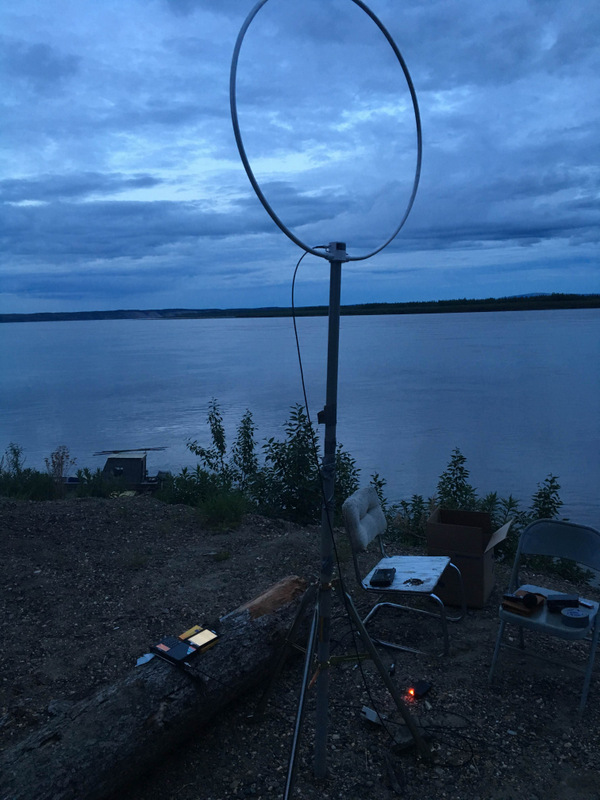
Paul Walker’s battery-powered Wellbrook antenna in remote Alaska.

Many thanks to SWLing Post contributor, Pete Jernakoff, who writes:

[…]I’m hopeful that one of your readers might be able to suggest a solution to my problem.

I have an older Wellbrook Communications active loop antenna that is powered by a 12 v AC-to-DC, center pin negative, plug-in power supply (Stancor AC Adapter, was supplied with the antenna).

I’d like to power the antenna from a rechargeable battery in order to make the antenna portable and to eliminate any noise that might be emanating from said power supply (which, as an aside, runs very warm when in operation).

My problem is that I cannot find any rechargeable batteries (lithium ion preferred) with a center pin negative output. All of the ones that I can find online have center pin positive outputs (such as the TalentCell 12V/6000mAh rechargeable battery that I’ve purchased to power my other, more recently produced, Wellbrook Communications active loop antenna whose amp needs a center pin *positive* input).

Thanks in advance for consideration of my request. Btw, love your blog! I’ve been an avid reader of it for quite some time now.

Post readers: If you have any suggestions for Pete, please comment with any relevant links to help him make the purchase. I’m guessing Pete isn’t interested in re-soldering a coaxial plug for negative tip polarity at this point.

By the way, I used a photo of Paul Walker’s Wellbrook at the top of this post because I recall that when he lived in Alaska, he powered his Wellbrook loop with a rechargeable pack (and during the winter, I also recall he struggled to keep it warm enough to provide power for any length of time!). Perhaps Paul can comment.

I’m so glad you enjoy the SWLing Post, Pete!

Beating the Quarantine Blues: Readers build homebrew NCPL antennas

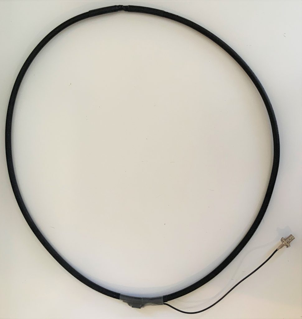
My homebrew version of the NCPL antenna.

Recently, I published a step-by-step guide on building a Noise-Cancelling Passive Loop (NCPL) antenna. Evidently, this antenna project really resonated with readers! [See what I did there? If so, my apologies!]

I think this passive loop antenna project has been so appealing because (1.) most of us around the world are sheltering at home due to the Covid-19 pandemic and (2.) this project is simple and you likely have all of the components in your tool shed or junk box at this very moment.

A number you have written to tell me about your antenna builds and some of you have agreed to allow me to share your projects with the SWLing Post community.

Below, you’ll find three fine homebrew examples of the NCPL antenna–all of which were made with what these fine radio enthusiasts had on-hand:

Jerome van der Linden

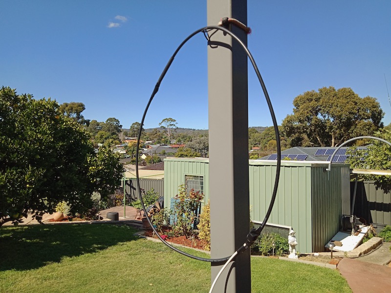
Jerome’s NCPL antenna

Jerome writes:

Hello Thomas,

Well, I took up the challenge and built a NCPL antenna pretty close to your instructions.

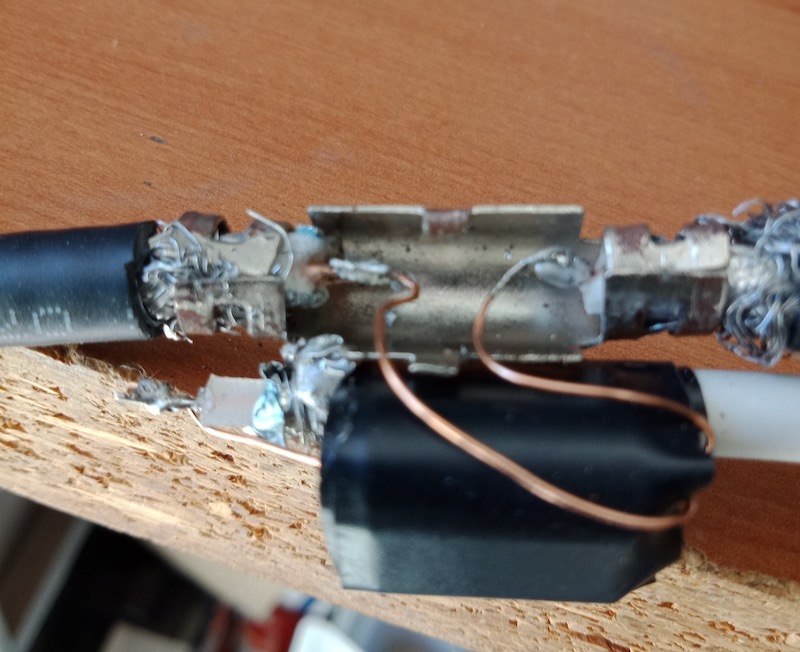
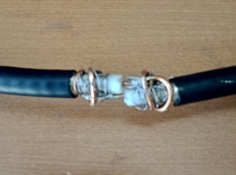
Unfortunately, the coax I had available used (had aluminium shielding, and too late into the project I discovered solder would not take to it. My solution was to cannibalize a coax cable joiner (see photos attached), where – normally – the centre conductors are joined / held by a plastic centre piece and screw fittings.

The braid / shield for the two bits of coax is clamped / squeezed by an outer metal piece. My cannibalising effort involved removing the plastic centre bit which joins the two centre cores, and keeping just the outer metal component which I used (after completely cutting through the coax) to clamp the two metal braid sections, while the two centre copper bits were far enough apart for me to solder the leads for the ferrite balun.

Of course, I could not do the same at the top of the loop where the internal and external conductors need to swap over. I soldered some quite thick copper wire (perhaps 2mm in diameter) to each center core, pushed the center core into the opposing coax and coiled the 2mm thick copper tightly around each end of the coax.

Once it was all taped up it looks no worse than yours, and it does indeed WORK! [see photo above]

Here in Oz, I could not source the identical ferrite, but I think it’s pretty close. Best performance for me is on 11MHz, where the Radio New Zealand signal on 11725 is markedly better using the loop than the internal whip on my Tecsun PL-880. Other bands not quite so significant, but the Noise level is definitely lower.

As you say, Jerome, once all packaged up, it looks great! Sure, the mixture of materials you had on hand wasn’t ideal (aluminium shielding, etc.) but you found a way to make it work from the resources you had in your home. And I love the fact it’s lowed your RFI level!  Thanks for sharing!

Giuseppe Morlè (IZ0GZW)

Dear Thomas,

I’m Giuseppe Morlè (IZ0GZW), from Formia, central Italy, on the Tyrrhenian Sea.

I wanted to build your noise canceling loop seen on SWLing Post …
seems to work well especially from 40 meters. upward…
the diameter is 50 cm.
I will do other tests soon.
You can see the initial test on my YouTube channel via this link:

Thanks for the nice idea and a greetings from Italy.
73. Giuseppe IZ0GZW

Thank you, Giuseppe! What an amazing view you have there from your balcony! I’m quite impressed your PL-660 can take advantage of this design so well. We look forward to your other tests! Grazie mille!

John Mills

Hi Thomas,

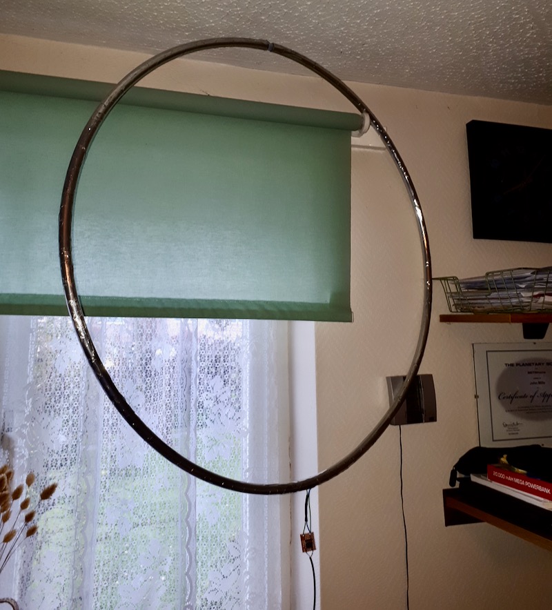
My idea was to use a fitness hoop 75cm diameter bought off eBay. I removed the flashy striping to reveal a plastic like hoop that was joined in one spot with a plastic insert.

I have wrapped the whole hoop in tin-clad copper foil tape that has a conductive adhesive backing, but to be sure I have soldered all the overlapping seams. I drilled two holes opposite each other for the upper foil connections and the lower exit to the Balun.

Hopefully the three pictures will be helpful, I did the 4 turn design on Airspys website and it works really well connected to my RSPdx.

73

John

Thank you, John. What a fantastic way to build the NCPL antenna without using a coax for the loop. Indeed, since your plastic hoop has a small insert in the middle, you’ve an ideal spot to make the shield to center conductor cross-over.  Very clever! I also like how you mounted the 1:1 Balun (or Unun) on a small board. Thanks for sharing this.

Got Loops?

Post readers: If you have your own unique NCPL antenna design, please consider sharing it with us! Contact me with details and photos. I’ll plan to publish at least one more post with examples here in the near future.


Do you enjoy the SWLing Post?

Please consider supporting us via Patreon or our Coffee Fund!

Your support makes articles like this one possible. Thank you!

Guest Post: Radiofreunde NRW’s DXpedition-grade signal distribution system


Many thanks to SWLing Post contributor, Joachim von Geisau (DH4JG), for the following guest post:


Signal distribution at SWL camps: The new JK-1000 HF distributor

by Joachim von Geisau (DH4JG)

The Friends of Radio NRW – an independent group of shortwave listeners and radio amateurs in Germany – have been organizing 2-3 SWL camps per year for a number of years, where they meet as far away as possible from electrical noise in order to listen to shortwave together.

To distribute antenna signals, we have previously used an RFT AVV01 antenna distributor.

At an SWL camp there are high demands on signal distribution. Both very weak and strong signals should be distributed well, un-distorted, without noise and other interference. The signal levels are approximately between 0.2 ?V (S1) to over 5 mV (S9 + 40 dB), with a frequency range of at least from 150 kHz to 30 MHz, thus broadcast bands from LW to SW are covered, also all amateur radio bands from 160 m to 10 m.

Popular among listeners are RFT AVV01 RF distributors from the former GDR, at least 30 years old. However, the use of an AVV01 has several disadvantages: high power consumption, difficulties in getting spare parts, high upkeep with corroded contacts and the like. In addition, the transmission of the LW/MW range drops, which is a disadvantage especially for MW listeners. The NV-14 system from Rohde & Schwarz from the late 1960s has the same weaknesses.

Two years ago, the desire arose to develop a concept for the replacement of the RFT system.
The following aspects were important:

  • Frequency range at least 100 kHz – 30 MHz, as linear as possible
  • frequencies below or above desirable
  • Running on 12 V DC or integrated noise-free power supply
  • Remote power supply for active antennas
  • Robust structure
  • Versatility
  • Hobby friendly budget

The amateur radio market offers several products for RF signal distribution (e.g., ELAD, Bonito et al.), but no solution to distribute 6-8 antennas to 10-12 receivers. It was clear from the beginning that DIY development was inevitable.

The starting point of the considerations was to integrate remote power supply for active antennas, an amplifier stage and a distribution network.

Such a distributor is able to distribute an antenna signal to several receivers; several antennas require several such distributors, which led to the decision to implement the project in plug-in technology.

With OM Frank Wornast DD3ZE (www.dd3ze.de), known e.g. for his converters, filters and the like, a well-known RF developer could be won, who took over the implementation of the concept based on the detailed specifications. OM Wornast first produced a prototype without remote power supply, which already did an excellent job of RF signal distribution.

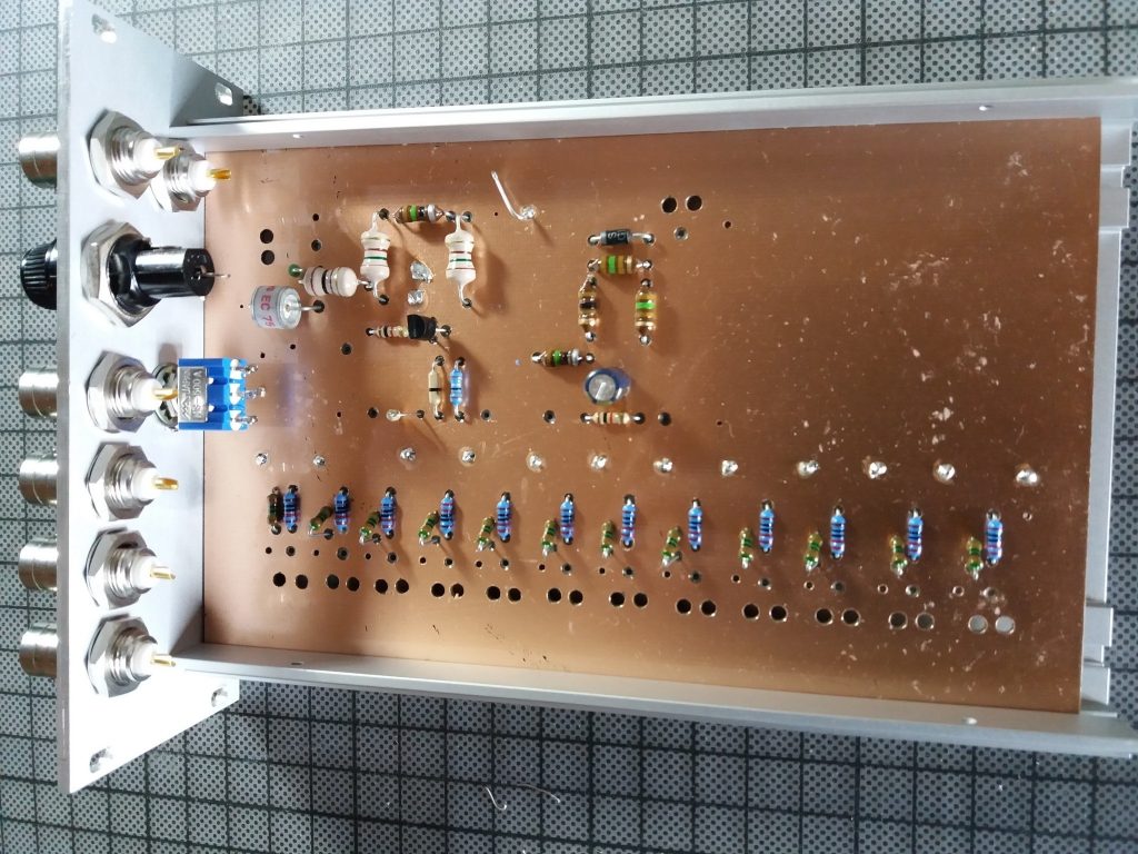
A “hardness test” at an SWL camp showed that this distribution module easily fulfilled our requirements: Frequency range 10 kHz – 50 MHz (also usable with a few dB loss above 50 MHz). Supplemented by a switchable remote power supply and a 90V gas discharger at the antenna socket, the final PCB layout was created, representing the core of the new HF distribution system of Radio Freunde NRW

The distribution block consists of the following components:

  • Input with 90V arrester & 100 kOhm MOX resistor to dissipate static interference
  • Remote power supply, switchable, 10-14 V, max. 350 mA
  • Amplifier stage with 14-14.5 dB
  • Resistor network for distribution

The device is characterized by a very smooth frequency response and has a very low inherent noise. It offers the possibility of using levels of -120dBm with very good SNR
to process up to strong levels of up to + 14dBm. In addition, the reception on VLF is now possible, which did not work with the previous system.


The PCB is designed in a very practical way: series resistors for LEDs are integrated as well as fixing points for coaxial cables. The remote power supply can be switched separately, but can also be used permanently by means of a jumper.

With this concept, the distribution block can be used universally: use on an active or passive antenna with distribution to several receivers, by means of a step switch in front of it also for several antennas; if you leave the remote feed path unconnected, the block can also be used as a simple distributor, so it is almost universal for hobby purposes.

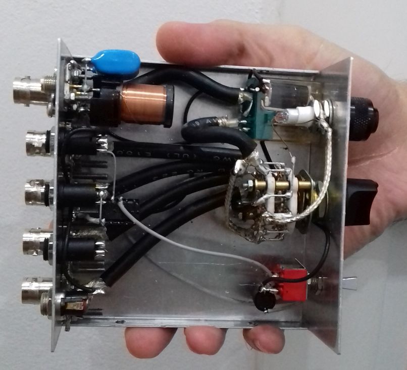
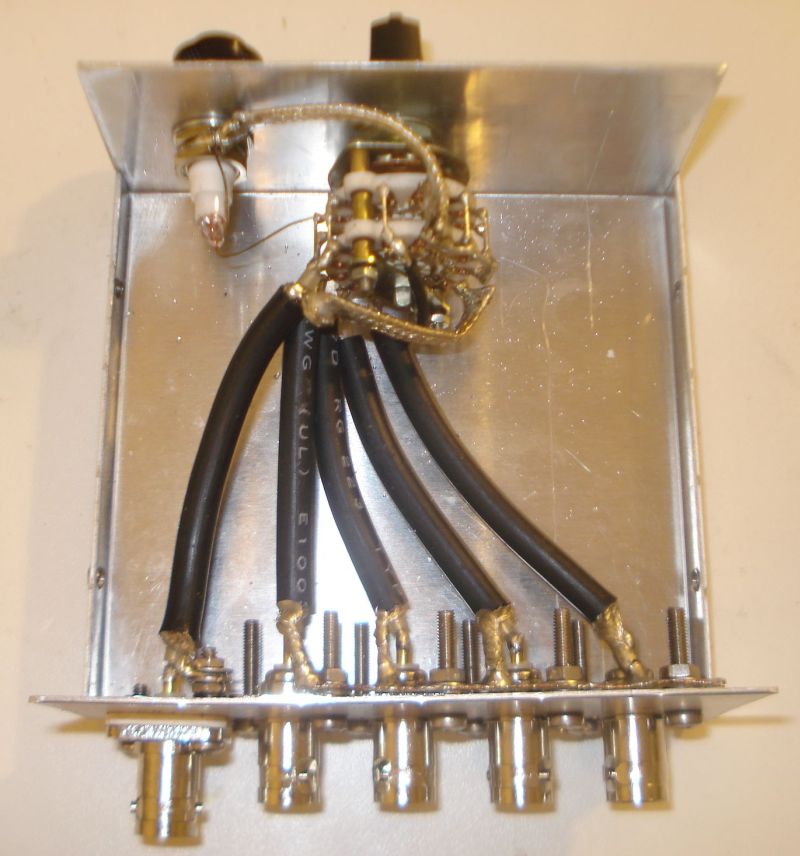
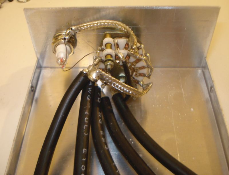
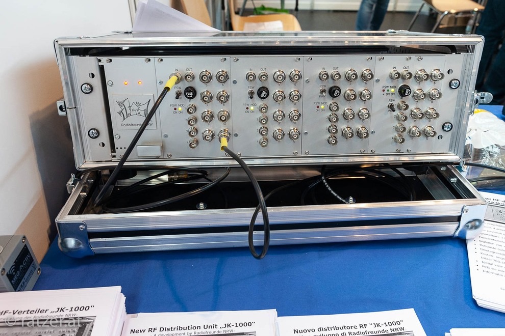
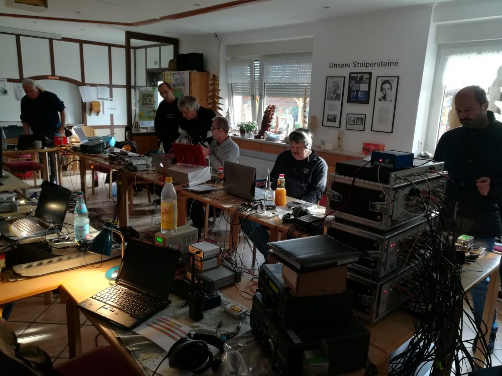
For use on SWL camps, we decided to install them in 19 “rack-mount technology. A standard rack can thus accommodate 4 distributors and a power supply, allowing  distribution of 4 antennas to 12 outputs each. An example of the installation is shown in the following picture: Parallel to the input is another BNC socket, which is connected via a C 100 nF where the input signal can be used DC-free for measurement purposes or the like. The distribution unit is installed in a transport case. The components themselves are mounted in slide-in housings which are provided with a corresponding front panel: Such front panels might be obtained from CNC manufacturers.

On the back + 12V DC must be supplied as operating voltage. For the power supply units, we opted for linear power supplies because we have made the best experience with these without interference. For a distribution unit with 4 slots, a power supply with 12V 1A is sufficient – each distribution block takes about 55 mA, an active antenna up to 150 mA, so even with “full load” a power supply with 1 A is sufficient. The distributor was tested with various well-known active and passive antennas, including a PA0RDT MiniWhip, active loops, long wires and T2FD.

Due to the wide input voltage range, the module can handle nearly any antenna. The cost for a distributor for 4 antennas amounts  (depending on the version: housing, sockets, switches, power supply, etc.) to about 700-1000 €. That may seem a lot at first glance. However, taking into account that a simple 5-gang distributor from mass production costs already around 250 ¬, the cost of the distribution of 4 antennas to each up to 12 outputs are not that much. The Friends of Radio NRW use two of these distribution units for SWL camps.

If you are interested in building one, please contact the author (dh4jg@darc.de) for further information. The development history of the distribution unit is also available at www.dx-unlimited.eu.


Wow!  What a beautifully engineered antenna distribution solution, Joachim!  I love how you worked together to sort out all of the requirements for your system then build it for ultimate performance and flexibility.  No doubt, you and your colleagues at  Radiofreunde NRW posses a lot of design and engineering skills!  Simply amazing and thank you for sharing your design with the radio community!

Contact Joachim for more details and check out notes and discussion at www.dx-unlimited.eu (may require registration).

Guest Post: ZIPWALL10 poles as antenna supports

Many thanks to SWLing Post contributor, Mario Filippi (N2HUN), who shares the following guest post:

ZIPWALL10 poles

Recently we had a remodeling job performed at the home QTH and the workers used telescoping poles to form a dust barrier.  When the job ended, they said I could have the telescoping poles, a product called ZIPWALL10, which when collapsed are four feet long but extend to ten feet.  This got me pondering about how handy these could be in the radio shack, especially for indoor impromptu antennas.

Close up of the ZIPWALL telescopic pole.

Indoor antennas, especially wire antennas usually have to be secured to a wall somehow, and should be as high as possible in the room.  That requires using adhesive tape to attach the wire and a ladder (most ceilings are eight feet), but using the ZIPWALL10 poles it’s easier and safer.  Below is a temporary random wire antenna in my shack using 26 gauge insulated wire strung between the two poles.

Random wire in shack room is a bit hard to see but it is strung between the two poles.

What’s nice about these poles is they have rubber feet to grip the floor and plastic pads on top to avoid damage to the ceiling. The top section is spring loaded to assure a tight fit.  The ZIPWALL10 model extends to ten feet in three telescopic sections. No tools are needed to set these up, and they conveniently collapse for storage.

ZIPWALL10 pair along with roll of 26 gauge wire for temporary indoor antenna installation.

These poles just happened my way due to a remodeling job, but surely other types are available on the market for those wanting to experiment with indoor antennas.  The price for a ZIPWALL10 pair on Amazon is around eighty dollars. Thanks for reading.


What a great use for ZipWall poles, Mario! I’ve spent the past few days at an ocean front condo and could have used two of those supports to suspend a small, lightweight passive loop antenna safely on the balcony. That’s fantastic your contractors simply gave you those poles! 

Thanks for the tip!

As you mention, Amazon sells a full line of ZipWall options (links below support the SWLing Post) but these can also be found at most home improvement stores. 

Ron’s thoughts on RFL200 and Q-Stick longwave antennas

Many thanks to SWLing Post contributor, Ron, who shares his thoughts on comparing two portable longwave antennas:

To begin, for reference, check out this post where The Professor reviews the RFA200. Also, check out the following video from the replies of that post:
Both the RFL-200 and the Q-Stick came in today.

Performance of both was very nearly identical but for now the Q-Stick wins on price ($67.50 vs. $75.78 delivered) and the Q-Stick does both LW and MW.

But Gerry says he’s going to close RadioPlus early next year so-presumably-
that will leave just the RFL-200 and its REA-200 sibling.

The “200” no doubt comes from the length, 200mm or 8 inches…the Q-stick
uses a 7-3/4 inch ferrite bar which is probably why the similar performance.

There is one thing: the small tuning knob is not hard to turn on the RFL-200
as it was on the REA-200 tested earlier but a bigger knob would be nice.

But the tuning cap uses a 1/8th inch shaft so finding a larger knob is too
much bother, most are for 1/4 inch shafts.

By comparison the Q-Stick has a nice big knob and is quite easy to tune.

So for now the Q-Stick would be the better buy, but don’t tarry.

[One more note,] if you want the most bang for your buck, forget both of these, get
a PK Loop
for $90.60 delivered (be sure to specify the 155-500 kHz model).

Thanks for sharing your thoughts, Ron!

Click here to check out the RFL200 longwave antenna on eBay.

(Click here to view the RFA200 mediumwave version.)

Click here to check out the Q-Stick antenna at Radio Plus. 


Do you enjoy the SWLing Post?

Please consider supporting us via Patreon or our Coffee Fund!

Your support makes articles like this one possible. Thank you!