Shortwave listening and everything radio including reviews, broadcasting, ham radio, field operation, DXing, maker kits, travel, emergency gear, events, and more
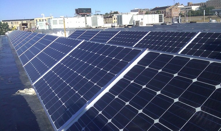
The Netherlands national amateur radio society VERON reports on the pollution problems caused by Solar Panels installed on homes
Electrical systems such as solar panel installations must comply with EMC (Electro Magnetic Compatibility) standards. That means that there is a limit to the electromagnetic fields (EMF) that an electrical system, such as the combination solar panel and inverter including cabling, may emit.
However, a 2014 study in 14 European countries by the EMC Administrative Cooperation Working Group found this emission limit is more often than not exceeded.
Many thanks to SWLing Post contributor, TomL, for the following guest post:
My Evolving, Morphing, SW Listening Station
by TomL, May 26, 2016
My interest in radio listening has been rekindled after a long hiatus in parallel to my dwindling interest in Mainstream Media. It is now about 8 years without cable TV and I seriously do not miss it, especially with the evolving nature of discovery with respect to other forms of media. SWL radio was important to me in my formative years during the Cold War; fascinating were the many ways governments used shortwave radio to influence populations, each with their own brand of propaganda! Young people today know nothing about the endless (and entertaining) tirades of East German editorial commentaries denouncing the evil, decadent West. Or, of the free, large-sized envelopes full of travel and promotional brochures, pennants, bumper stickers, and booklets sent from the government broadcasters such as Poland, Hungary (yes, communist countries!), Australia, Netherlands, etc. just for sending in one simple QSL report!!!
I quickly realized that those days are gone forever, consigned to a period of history where radio was THE main method of disseminating copious amounts of government propaganda to very large swaths of humanity. Now, the internet and cable TV fulfill that function in a much more CONTROLLED manner, both technically and socially (Big Brother like). So, I have diversified my interests and have an unusual listening station. It is multiple things in one small space. You see, I live in a very small condo in a noise-plagued environment with only a 2nd floor wooden deck (owned by the Condo Association!) in which to put up any outside antennas. Only a single “Dish” type antenna is allowed. So my shortwave antenna needs to be well hidden. Same for the TV antenna, since I also have a north-facing deck, I cannot have any line-of-sight to the Southern sky for a Dish.
The first wire antenna strung from the top and brought inside was a dismal failure receiving nothing but noise. I gave up for a couple of years. I built a loop TV antenna and mounted an FM antenna instead since those were less susceptible to noise issues. Also recently added to this station are two cheap 4G antennas with wires into a single Verizon USB aircard plugged into my computer and getting up to 14 mbps performance.
But, I still wanted to try shortwave radio again (and medium wave too) but the noise issues were very, very discouraging. S9 noise on some bands. Tried preselector, a noise “phaser”, different lengths. Nothing worked. However, I read something from an amateur radio operator in Northern California who had a space problem. He put up a helically-wound-vertical (HWV) antenna with radials for 160 meters (John Miller HWV antenna). I also read about various “broomstick” antennas. So, I tried my own version with an old RF Systems Magnetic Longwire Balun I still owned and NO radials. Put it together with a 2 foot long, 4 inch schedule 40 PVC pipe wrapped in 200 feet of 18 awg magnet wire. Well, still noisy but, at least now I had a portable antenna!
So, I went camping in March of this year! Holy Cow, was it cold out but the helical antenna performed well enough to hear All India Radio for my very first time, a small 1kw Mexican station in the 49 meter band, and various others from Asia that were elusive for me in the distant past. I was finally encouraged again to continue my research. I did this a few more times and finally got tired of going camping just to listen to a radio! NOISE at home was still the big bugaboo to kill (and it still is).
I read up on Common-mode noise travelling on ground and shield components of antenna systems. So I bought a bunch of toroid ferrites of different types to cover different frequencies (something about initial permeability….) to make my own homemade “Super RF Choke” to cover all frequencies made on a Home Depot Homer bucket lid, winding the coax 5 or 6 times through all the toroids, the full diameter of the lid.
Measurements by Jim Brown published on the web (RFI-Ham.pdf), pages 32-33) indicate good choke performance using coax with these larger-sized coils. I still hoped to salvage the use of the HWV antenna. So, added the choke and noticed some improvement across most bands (less noise). Medium wave broadcast was not effective and decided that I did not want to keep tuning an antenna that HAD to sit outside to get away from the noise inside my listening station.
I also shut off the power to my condo and found out which noise sources were mine vs. other noise that came from all the neighbors (very important step to do!!!). For instance, I did not know before that USB charging adapters are PURE RF-NOISE EVIL in an innocently small package?!?!?! I rearranged wiring to shut off certain devices and power strips when I want to listen to the radio!
So, I kept reading. Found out about another magnetic balun from Palomar. Tried it but not impressed – performance was too lossy compared to the good old RF Systems MLB (what a great product that was back then!). Kept reading and found out good things about the EF-SWL from PAR electronics (product is now made and sold by LNR). The ground connections on it (and the Palomar) intrigued me. So, I decided to go to Hamvention for the first time, even though I was skeptical of finding anything useful, I told myself, I could at least buy the EF-SWL on sale (which I did).
Installed EF-SWL to the HWV but no difference compared to the RF MLB. The antenna did perform better outside on the deck in the far corner, so there it still sits. Then, I hooked up the wire they gave me with the EF-SWL to the ground and it resulted in MORE noise. Then, took off the jumper (which connects the coax shield to the ground side of the balun) and connected only the middle post (balun ground) to the ground wire and a lot LESS noise resulted along with a small reduction in radio signal level!!! Finally some progress – the wire seems to be acting like an old-fashioned “counterpoise”, which is misunderstood these days. Apparently, back in the 1930’s-1950’s, people involved in radio knew the differences between an “earth ground”, a “radial system”, and a “counterpoise”. Technically, they are all different and their use is different as a result. Now, people moosh all these concepts together interchangeably which risks creating very ineffective antennas.
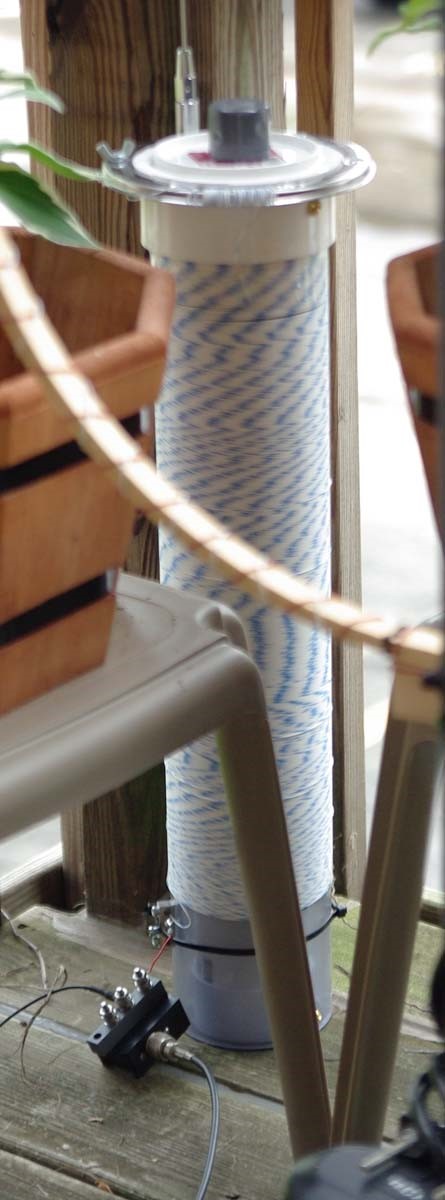
Photo of installed EF-SWL at the bottom of the HWV with coax at the output, the red magnet wire input on top, the middle post for the counterpoise wire, and the coax shield post is unused.
The HWV antenna now has 600 feet of 26 awg teflon wire on the outside PVC, an inside 3 inch PVC “sleeve” with 102 Russian ferrite rods, a 56 inch stainless steel whip at the top, and one inch hole through the center to accommodate the 7 foot PVC mount to my carbon fiber photo tripod when I take it camping again.
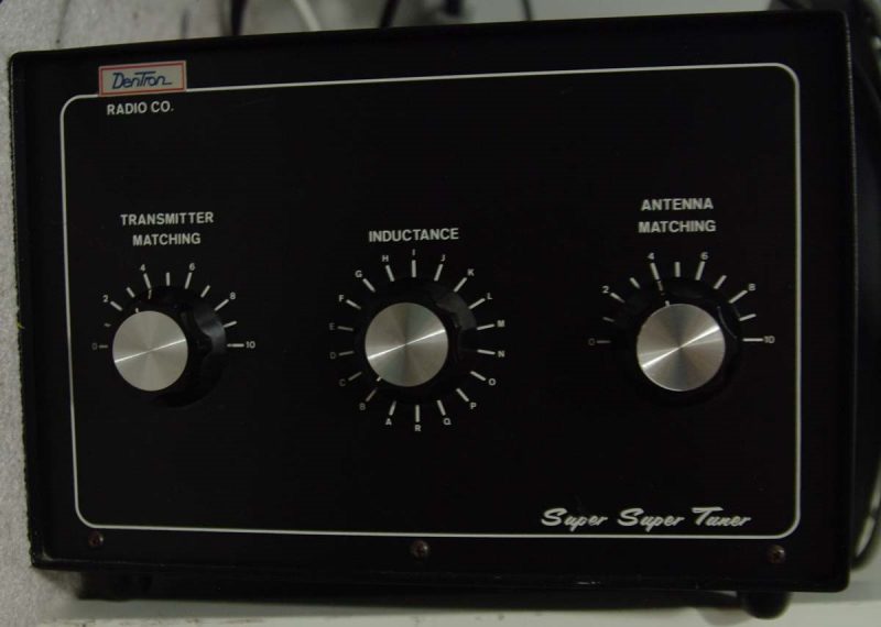
So, I am on a new quest to understand counterpoises, how to actually TUNE them and, hopefully, how to use them to increase the performance of shortened antennas like my HWV (something about reducing the dB loss incurred by shortening….). A second result I hope will be how to use the counterpoise to keep signal-to-noise ratio high at the same time (maybe with this used $100 Dentron Super Tuner bought at Hamvention?).
If input directly to the input of the radio, led to more reduction in noise and signal!! Too much actually, so I took off my Super RF Choke and now I had a better result compared to the EF-SWL with the RF Choke (slightly cleaner sound with less hissy noise). Apparently, the GI300 completely isolates the coax shield, better than my homemade choke! The requirement is to use coax from the feedpoint and not bare wire. I then placed a few clamp-on ferrites I bought from eBay to help with slightly higher frequency choking of the shield at various places on the feedline.
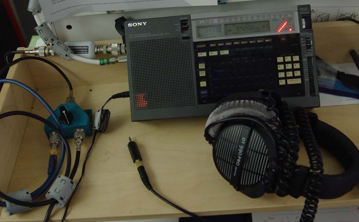
Photo of GI300 on radio with NO extra coax lead into the radio at right (Thanks to Dennis Walter of Bonito for that tip)
Before Hamvention, I wanted to try out AM broadcast. I wanted to know more about this “FSL” antenna a well-known eccentric from Ireland (Graham Maynard FSL) developed before he passed away a few years later. So read up and bought a whole bunch of ferrite rods and tried different configurations. Well, my particular design did not work all that well because I did not follow directions for winding wire into a balanced design. So, I added all those ferrite rods to the 2 foot HWV (inside a 3 inch thin-walled sewer PVC pipe). The antenna is louder down to about 3 MHz with a stronger signal (including noise) than without. I do not have measurements, and find it too time consuming to document. Maybe one day, I will compare and document by sliding the ferrites out on the 3 inch PVC and measure actual signal levels. The ferrite sleeve seemed to pick up MORE noise and radio signal than without it. So, if you need more signal strength in a small package below 7 MHz, then the idea seems to have merit. But since it increased noise as much as radio signals, it has limited usefulness to me. I do have another project where I will put ferrite bars onto a tuned medium wave loop antenna (Tecsun AN100) that is much more portable and directional. The bars and loop were both relatively inexpensive from eBay. The ferrites change the tuning lower, so I have to figure out how to make it tune higher again…….
Photo of unfinished MW loop project.
Summary
Evolving understanding of dealing with major problems like overwhelming noise and limited space have led to unexpected additions to my SW Listening Station:
A 2 foot long, 4 inch diameter helically-wound-vertical antenna (HWV) with way too much wire on it (and now inserted with 102 160mm Russian ferrite rods on a 3 inch diameter “sleeve”). Originally built because of its portability. Can now be mounted on a carbon fiber photo tripod with a 7 foot 3/4” PVC pipe through the center length
A magnetic balun from LNR (designed by Parfitt) attached at the feedpoint of the antenna
A proprietary galvanic isolator from Bonito attached right at the radio’s antenna terminal
A “boat anchor” Dentron Super Tuner attached to the HWV feedline to help tune it
An unfinished MW loop antenna with more ferrite bars
An unused, homemade toroidal Super RF Choke
Clamp-on ferrites everywhere in proximity on wires and power leads
Re-arranged power strips and wires as needed for easier shutoff in functional groups
For shortwave, I still pick up mostly noise on many bands. With the uncalibrated S-meter on the ICF-2010 – 49 meters is around S1 (before about S3). 31 meters is MUCH improved and is now listenable to stronger stations (S2 instead of S7 noise!). Even 19 and 16 meters is improved from S6 to S7 down to about S3 now – noise still too annoyingly loud to understand any language being spoken however. And forget about DXing from this location! Will have to go camping again soon.
BUT, listening now to Voice of Greece, Radio Nacional Brasilia, or Radio Romania International is a much cleaner sounding experience than just a couple of months ago. They are there to re-discover and appreciate, even though many speak a foreign language and I do not understand a word they are saying! Also, there is the odd observation (like just this morning), that I can actually learn to enjoy listening to Country Music if it is the unique sounding Australian flavor!!
Do I miss cable TV?? Not a bit!!
Future investigations
Employ the Dentron Super Tuner in various configurations to find any improvements (currently attached to the coax of main feedline from the EF-SWL, it is helping tune different SW bands (not sure why it helps, does not make sense, must be a mismatch between coax and balun)
Obtain old book(s) on counterpoises
Get a Linear DC power supply for use with all the EVIL RF-spewing devices that use 5 volts. Maybe this one: (Tekpower 3Amp Linear)
Replace any cheap/old RG58 cables with LMR-240 or similar
Finish the AM loop w/ferrites so I can take it places
Perhaps an ultra low-noise outdoor amplifier for the HWV, depends on counterpoise experiments: (Wellbrook ALA100M-2) (I don’t want to spend that much money now)
Somehow use a noise antenna with a better phaser: (DX Engineering NCC-1) (gulp, don’t want to spend THAT much money now also!!!)
Get some relief from background noise using a really robust noise blanker. I don’t want to spend on the portable radio, would rather get something like the Bonito 1102S or an ELAD model both supposed to have excellent audio quality and excellent DSP noise blankers. But that means getting a cheap laptop to run it and replacing the Sony. MOAR big bucks…. but not right now
Maybe a real loop antenna, BUT it has to be remotely tunable and remotely turnable and small enough to HIDE. MOAR big bucks, sigh….
TomL from noisy Illinois, USA
Many thanks for sharing your experiences, Tom! Also, it was great meeting you at the Hamvention this year.
I must say that there is something to be said for brute-force experimentation when it comes to mitigating radio interference. I hope you keep us posted as you continue to experiment and improve upon your unique listening system.
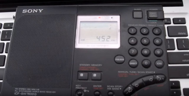
Here’s my Mac Book Pro (2010 model) playing Mary Had A Little Lamb over the radio, by modulating the RFI (Radio Frequency Interference) produced by it and other computers. As picked up on a Sony 7600G receiver. I found the best reception was on the long wave band, although I could continue to hear it well above the AM (medium wave) band, past 1700 kHz. The signal was pretty much everywhere, no matter where I tuned, in 1 kHz steps.
Picking up radio emissions from computers is one method that can be used to spy on them.
That is fascinating, Chris. While I was well aware that computers and mobile devices (of all stripes) produce RFI, I had no idea that it could be used for spying. I love how you’ve manipulated this interference to play a tune! What a creative hack!
Many thanks to SWLing Post contributor, London Shortwave, who is kindly sharing this guest post–a brilliant article he recently posted on his own website.
I’m very grateful: one of the most common questions I’m asked by readers is how to cope with the radio interference so many listeners and amateur radio operators experience in high-density, urban areas. If this is you, you’re in for a treat–just keep reading:
Dealing with Urban Radio Interference on Shortwave
Shortwave radio listening is an exciting hobby, but for many of us city dwellers who either got back into it recently or tried it out for the first time not long ago, the first experience was a disappointing one: we could barely hear anything! Station signals, even the supposedly stronger ones, were buried in many different types of static and humming sounds. Why does this happen? The levels of urban radio frequency interference, or RFI, have increased dramatically in the last two decades and the proliferation of poorly engineered electronic gadgets is largely to blame. Plasma televisions, WiFi routers, badly designed switching power adapters and Ethernet Over Powerlines (also known as powerline network technology, or PLT) all severely pollute the shortwave part of the radio spectrum.
Does this mean we should give up trying to enjoy this fascinating medium and revert to using the TuneIn app on our smartphones? Certainly not! There are many angles from which we can attack this problem, and I shall outline a few of them below.
Get a good radio
The old adage “you get what you pay for” certainly holds true even when it comes to such “vintage” technologies as shortwave radio. Believe it or not, a poorly designed receiver can itself be the biggest source of noise on the bands. That is because many modern radios use embedded microprocessors and microcontrollers, which, if poorly installed, can generate interference. If the receiver comes with a badly designed power supply, that too can generate a lot of noise.
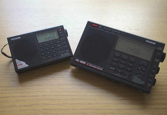
So how does one go about choosing a good radio? SWLing.com and eHam.net have fantastic radio review sections, which will help you choose a robust receiver that has withstood the test of time. My personal favourites in the portable category are Tecsun PL310-ET and Tecsun PL680. If you want a desktop radio, investigate the type of power supply it needs and find out whether you can get one that generates a minimal amount of noise.
It is also worth noting that indoor shortwave reception is usually best near windows with at least a partial view of the sky.
Tecsun PL310-ET and Tecsun PL680, my two favourite portable shortwave radios.
Identify and switch off noisy appliances
Many indoor electrical appliances generate significant RFI on the shortwave bands. Examples include:
Plasma televisions
Laptop, and other switching-type power supplies
Mobile phone chargers
Dimmer switches
Washing machines / dishwashers
Amplified television antennas
Halogen lighting
LED lighting
Badly constructed electrical heaters
Mains extension leads with LED lights
Identify as many of these as you can and switch them all off. Then turn them back on one by one and monitor the noise situation with your shortwave radio. You will most likely find at least a few offending devices within your home.
Install an outdoor antenna
If you have searched your home for everything you can possibly turn off to make reception less noisy but aren’t satisfied with the results, you might want to look into installing and outdoor antenna. That will be particularly effective if you live in a detached or a semi-detached property and have a garden of some sort. Of course, you will need a radio that has an external antenna input, but as for the antenna itself, a simple copper wire of several metres will do. An important trick is making sure that the noise from inside your home doesn’t travel along your antenna, thus negating the advantage of having the latter installed outside. There are many ways of achieving this, but I will suggest a configuration that has worked well for me in the past.
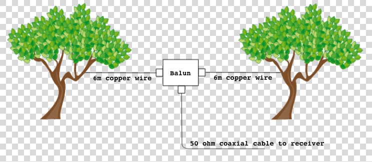
Fig.1 Schematic for an outdoor dipole antenna.
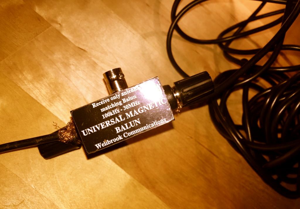
I have used a three-terminal balun (positioned outdoors), and connected two 6 metre copper wires to its antenna terminals to create a dipole. I then connected the balun to the radio indoors through the feed line terminal using a 50? coaxial cable. In the most general terms, the current that is generated in the antenna wires by the radio waves flows from one end of the dipole into the other, and a portion of this current flows down the feed line into your radio. The balun I have used (Wellbrook UMB130) is engineered in a way that prevents the radio noise current from inside your house flowing into the receiving part of the antenna.
Wellbrook UMB130 balun with the feed line terminal disconnected
Antenna preselectors
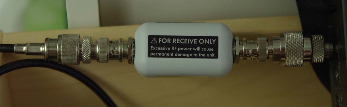
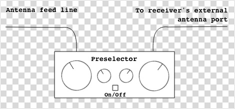
There is a catch with using an outdoor antenna described above — the signals coming into your radio will be a lot stronger than what would be picked up by the radio’s built-in “whip” antenna. This can overload the receiver and you will then hear many signals from different parts of the shortwave spectrum “mixing in” with the station you are trying to listen to. An antenna preselector solves this problem by allowing signals from a small yet adjustable part of the spectrum to reach your radio, while blocking the others. You can think of it as an additional tuner that helps your radio reject unwanted frequencies.
Fig.2 Schematic of a preselector inserted between the outdoor antenna and the receiver
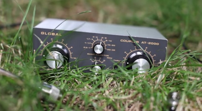
There are many antenna preselectors available on the market but I can particularly recommend Global AT-2000. Although no longer manufactured, many used units can be found on eBay.
Global AT-2000 antenna coupler and preselector
Risk of lightning
Any outdoor antenna presents the risk of a lightning strike reaching inside your home with devastating and potentially lethal consequences. Always disconnect the antenna from the receiver and leave the feed line cable outside when not listening to the radio or when there is a chance of a thunderstorm in your area.
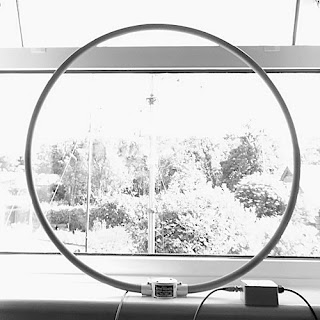
Get a magnetic loop antenna
A broadband loop antenna (image courtesy of wellbrook.uk.com)
The outdoor long wire antenna worked well for me when I stayed at a suburban property with access to the garden, but when I moved into an apartment well above the ground floor and without a balcony, I realised that I needed a different solution. Having googled around I found several amateur radio websites talking about the indoor use of magnetic loop receive-only active antennas (in this case, “active” means that the antenna requires an input voltage to work). The claim was that such antennas respond “primarily to the magnetic field and reject locally radiated electric field noise”[*] resulting in lower noise reception than other compact antenna designs suitable for indoor use.
Interlude: signal to noise ratio
In radio reception, the important thing is not the signal strength by itself but the signal to noise ratio, or SNR. A larger antenna (such as a longer copper wire) will pick up more of the desired signal but, if close to RFI sources, will also pick up disproportionately more of the local noise. This will reduce the SNR and make the overall signal reading poorer, which is why it is not advisable to use large antennas indoors.
The other advantage of a loop antenna is that it is directional. By rotating the loop about its vertical axis one can maximise the reception strength of one particular signal over the others, once the antenna is aligned with the direction from which the signal is coming (this is termed “peaking” the signal). Similarly, it is possible to reduce the strength of a particular local noise source, since the loop is minimally sensitive to a given signal once it is perpendicular the latter’s direction (also known as “nulling” the signal).
It is further possible to lower the effect of local noise sources by moving the antenna around. Because of the antenna’s design, the effect of radio signals is mostly confined to the loop itself as opposed to its feed line. Most local noise sources have irregular radiation patterns indoors, meaning that it is possible find a spot inside your property where their effects are minimised.
Many compact shortwave loop antennas require an additional tuning unit to be attached to the loop base (much like the preselector described above) but broadband loops do not. Wellbrook ALA1530S+ is one such antenna that is only 1m in diameter, and it was the one I chose for my current apartment. I was rather impressed with its performance, although I found that I need to use a preselector with it as the loop occasionally overloads some of my receivers when used on its own. Below is a demo video comparing using my Tecsun PL680’s built-in antenna to using the radio with the Wellbrook loop.
As you can hear, there is a significant improvement in the signal’s readability when the loop is used.
Experiment with a phaser
Although the loop antenna dramatically reduces the levels of ambient RFI getting into the radio, I also have one particular local noise source which is way too strong for the loop’s nulling capability. Ethernet Over Powerlines (PLT) transmits data across domestic electrical circuits using wall socket adapters, as an alternative to wireless networking. It uses the same frequencies as shortwave, which turns the circuits into powerful transmitting antennas, causing massive interference. One of my neighbours has PLT adapters installed at his property, which intermittently become active and transmit data. When this happens, it is not merely noise that is generated, but a very intense data signal that spreads across the entire shortwave spectrum, obliterating everything but the strongest stations underneath. Fortunately, a mature piece of radio technology called antenna phasing is available to deal with this problem.
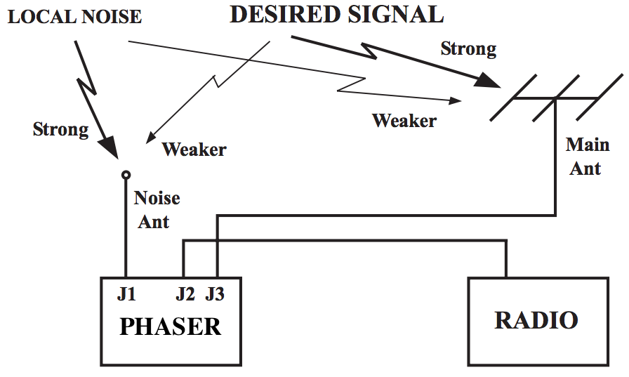
Fig.3 The principle of antenna phaser operation (adapted from an original illustration in Timewave ANC-4’s manual)
Signal cancellation using phase difference
A phaser unit has two separate antenna inputs and provides one output to be connected to the radio’s external antenna input. The theory of phase-based signal cancellation goes roughly as follows:
The same radio signal will arrive at two different, locally separated antennas at essentially the same time.
The phase of the signal received at the first antenna will be different to the phase of the same signal received at the second antenna.
This phase difference depends on the direction from which the signal is coming, relative to the two antennas.
The phaser unit can shift the phases of all signals received at one antenna by the same variable amount.
To get rid of a particular (noise) signal using the phaser unit:
the signal’s phase at the first antenna has to be shifted by 180° relative to the signal’s phase at the second antenna (thus producing a “mirror image” of the signal received at the second antenna)
its amplitude at the first antenna has to be adjusted so that it is the same as the signal’s amplitude at the second antenna
the currents from the two antennas are then combined by the unit, and the signal and its mirror image cancel each other out at the unit’s output, while the other signals are preserved.
Noise sampling antenna considerations
To prevent the possibility of the desired signal being cancelled out together with the noise signal — which can happen if they both come from the same direction relative to the antennas — one can use the set-up illustrated in Figure 3, where one antenna is dedicated to picking up the specific noise signal, while the other is geared towards receiving the desired broadcast. That way, even if the phases of both the noise and the desired signals are offset by the same amount, their relative amplitude differences will not be the same, and thus removing the noise signal will not completely cancel out the desired signal (though it will reduce the latter’s strength to some extent).
It is possible to use any antenna combination for phase-based noise signal cancellation. However, one has to be careful that, in the pursuit of removing a specific noise source, one does not introduce more ambient RFI into the radio system by using a poorly designed noise-sampling antenna. After all, the phaser can only cancel out one signal at a time and will pass through everything else picked up by both antennas. This is particularly relevant in urban settings.
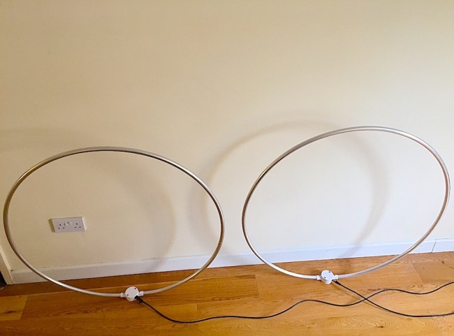
For this reason, I chose my noise sampling antenna to also be a Wellbrook ALA1530S+. The additional advantages of this set-up are:
It is possible to move both loops around to minimise the amount of ambient RFI.
By utilising the loops’ directionality property, one can rotate the noise sampling loop to maximise the strength of the noise signal relative to the desired signal picked up by the main antenna loop.
Two Wellbrook ALA1530S+ antennas combined through a phaser
And now onto the phaser units themselves.
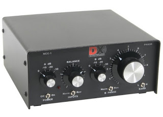
Phaser units
DX Engineering NCC-1 (image courtesy of dxengineering.com)
I have experimented at length with two phaser units: the MFJ 1026 (manual) and DX Engineering NCC-1 (manual). Both solve the problem of the PLT noise very well, but the NCC-1 offers amplitude and phase tuning controls that are much more precise, making it a lot easier to identify the right parameter settings. Unfortunately this comes at a price, as the NCC-1 is a lot more expensive than the MFJ unit. As before, a preselector is needed between the phaser and the radio to prevent overloading.
Below is a demo of DX Engineering NCC-1 at work on my neighbour’s PLT noise. I have chosen to use my SDR’s waterfall display to illustrate the nefarious effect of this type of radio interference and to show how well the NCC-1 copes with the challenge.
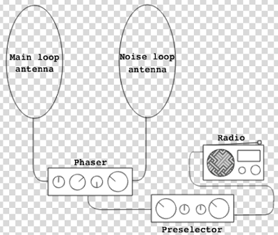
Cost considerations
Fig.4 Final urban noise mitigation schematic
It would be fair to say that my final urban noise mitigation set-up, shown in Figure 4, is quite expensive: the total cost of two Wellbrook antennas ($288.38 each), a DX Engineering phaser ($599.95) and a Global AT2000 preselector ($80) comes to $1257. That seems like an astronomical price to pay for enjoying shortwave radio in the inner city! However, at this point another old saying comes to mind, “your radio is only as good as your antenna”. There are many high-end shortwave receivers that cost at least this much (e.g. AOR AR7030), but on their own they won’t be of any use in such a noisy environment. Meanwhile, technological progress has brought about many much cheaper radios that rival the older benchmark rigs in terms of performance, with Software Defined Radios (SDRs) being a particularly good example. It seems fair, then, to invest these cost savings into what makes shortwave listening possible. You may also find that your RFI situation is not as dire as mine and you only need some of the above equipment to solve your noise problems.
Filter audio with DSP
If you have implemented the above noise reduction steps but would still like a less noisy listening experience, consider using a Digital Signal Processing (DSP) solution. There are a number of different approaches and products available on the market, and I shall be reviewing some of them in my next post. Meanwhile, below are two demo videos of using DSP while listening to shortwave. The first clip shows the BHI Compact In-Line Noise Elimination Module at work together with a vintage shortwave receiver (Lowe HF-150). The second video compares using a Tecsun PL-660 portable radio indoors on its own and using the entire RFI mitigation set-up shown in Figure 4 together with a DSP noise reduction feature available in the SDR# software package, while using it with a FunCube Dongle Pro+ SDR. As a side note, it is worth remembering that while DSP approaches can make your listening experience more pleasant, they can’t recover what has been lost due to interfering signals or inadequate antenna design.
Set up a wireless audio relay from your radio shack
The above RFI mitigation techniques can result in a rather clunky set-up that is not particularly portable, confining the listener to a specific location within their home. One way to get around this is by creating a wireless audio relay from your radio shack to the other parts of your house. I did this by combining the Nikkai AV sender/receiver pair and the TaoTronics BA01 portable Bluetooth transmitter:
Head for the outdoors!
So you have tried all of the above and none of it helps? As a last resort (for some, but personally I prefer it!), you can go outside to your nearest park with your portable radio. After all, if shortwave listening is causing you more frustration than joy it’s hardly worth it. On the other hand, you might be surprised by what you’ll be able to hear with a good receiver in a noise-free zone.
Acknowledgements
Many of the above tricks and techniques were taught to me by my Twitter contacts. I am particularly grateful to @marcabbiss, @SWLingDotCom, @K7al_L3afta and@sdrsharp for their advice and assistance over the years.
Thank you–!
What I love about my buddy, London Shortwave, is that he didn’t give up SWLing just because his home is inundated with radio interference–rather, he saw it as a challenge. As you can see, over the years, he has designed a system that effectively defeats radio interference.
I also love the fact that he uses an even more simple approach to defeating RFI: he takes his radio outdoors. A kindred spirit, indeed.
I encourage all SWLing Post readers to bookmark and search London Shortwave’s website. It’s a treasure trove for the urban SWL. We thank him for allow us to post this article in its entirety.
Many thanks to SWLing Post reader, Mike who notes that Radio France International’s program, The Sound Kitchen, is now available over shortwave radio.
The Sound Kitchen staff reported this news in the show notes of their latest episode, Pieces of Eight:
“Fabulous news! We have a shortwave frequency again! It’s 13725 kHz, on the 22m band; you can hear us between 6.00 and 7.00 UT every day! We’ve had reception reports from New Zealand, Japan, Bangladesh and the UK, and although the frequency is “aimed” (or however that works) towards the African continent, give it a try! You never know!”
Fabulous news, indeed! Though–as they state–North America is not the target of this broadcast frequency and time, I will certainly be listening as night time openings on the 22M band are certainly possible. I imagine those of you in Africa, Asia and the Pacific can receive The Sound Kitchen with relative ease.
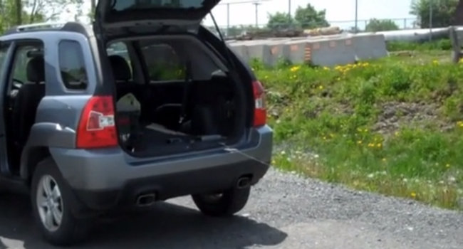
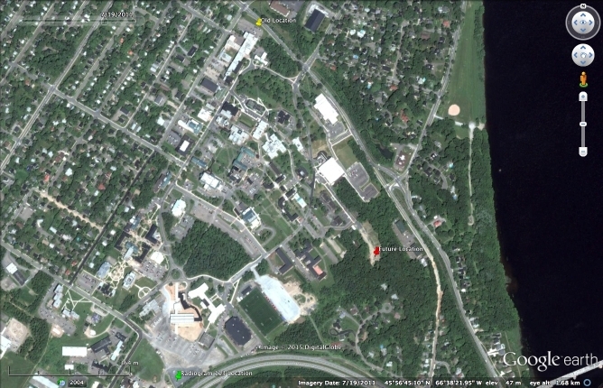
SWLing Post contributor, Richard Langley, has been seeking the perfect spot on the campus of the University of New Brunswick (UNB) to listen to shortwave. He recently shared the following:
Richard goes on to say that he’s found an even better location:
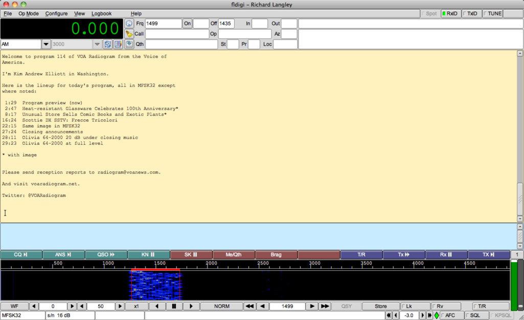
“That location on campus (green pin on attached image) turned out to not be noise-free on all bands. Found an even better location (red pin). Negligible power-line interference although still within Wi-Fi range of UNB’s system but no significant effects from that discovered yet. Got excellent reception of VOA’s Radiogram this past Saturday afternoon. Extremely clean waterfall in Fldigi. And virtually noise-free images [below]”
Richard’s decoded message. (Click to enlarge)
VOA Radiogram decoded image
Many thanks for sharing this with us, Richard!
Those of you who live or work in areas with significant radio noise should consider scouting out a listening spot like Richard has. Also, you might be inspired by LondonShortwave who takes his radios to public parks. Regardless, moving your receiver as far away from sources of radio interference as possible will always yield better listening results.
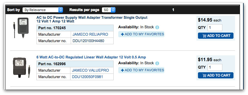
Over the years some of (but not all) these Jameco linear regulated power supplies are no longer clean for radio use.
Without changing the model number or description of the product, they have made changes with some (or much of ??) this “Linear Regulated” adapter line. Indeed they are still using a good old power transformer, but when it comes to the regulator part of the adapter, they have gone to switching type regulator device. So it produces a nice strong whine on a radio receiver just as a full fledged switching supply.
I had purchased a number of these so called linear supplies (sorry I no longer have the exact model number noted that I ordered) and experienced awful interference with any radio receiver. So I cracked open one of these to see what was up here and sure enough it was using a MC34063A inverting switching regulator .
Called Jameco and they flat out denied that they were using any switching devices in this Regulated LINEAR Jameco ReliaPro adapter. So I then sent a nasty gram email to the CEO of Jameco. I received an email back (was from the CEO too) and after some research they FINALLY did admit a change was made in some of the product line to use of a switching regulator . But he strongly made the point they would continue to still market these adapters as totally linear (yeah right ….nice guys).
I must add here that it does (or did not) NOT affect the entire line of these linear regulated adapters. About a year ago I ordered more (already had a few before) of the 12 volt 1 AMP model 170245 , and these are (or were anyway) totally clean and are excellent.
Also note that Jameco purchases up surplus “linear regulated” adapters from time to time. This 6 volt 500 ma one here is an example and is (or was anyway) nice clean one and uses no switching regulators. Our 2 tested samples of this adapter from about 5 years ago used a nice 7806 analog regulator. Perfect for use with many SW portables, (including the Sony ICF-SW7600GR with a plug change). But a warning again from experience , they are all subject to changes without any warning (and this one may have changed too for all we know ??)
They appear to stick the ReliaPro name as the manufacture on all adapters (if it was made by Jameco or not)
So Caveat Emptor.”
Duly noted, Dave! I’ve also noted that not all of the power supplies on their linear power supply page are listed as being a linear supply (see screen grab at top of page).
I may contact Jameco about this too and see if they can adjust their search results to properly reflect a selection of regulated linear supplies.