Hi there, I’m sure some of you will read the title of this post and conclude ‘that’s exactly that the Eton Satellit could never be’. I was of the same opinion, having read many reviews online suggesting this little radio on shortwave at least was essentially a bit ‘duff’ as we say in the UK. The fundamental flaws identified when it was first released included, but were not limited to – a general lack of sensitivity, poor AM SYNC stability and poor AM SYNC audio, poor filtering, particularly in SSB mode, muting whilst tuning, poor display visibility in sunlight, poor AGC timing…the list goes on.
On MW and FM there was a general consensus that this little radio performed very well, but with all the other flaws highlighted here, it certainly did not represent good value for money. A number of reviewers concluded that the Eton was an insult to the ‘Satellit’ brand. Oh dear, yet another shot in the foot for Eton then. User perception was confirmed when I posted my first reception video using this radio – a number of my Oxford Shortwave Log subscribers got in touch to say they were essentially scared off buying this radio at the time and that this was of course driven by the negative reviews that proliferated the internet.

Since the original launch, however, it would appear that firmware updates have improved this receiver immesurably, although I am quite certain this news hasn’t really filtered out into the market because there still appears to be a consensus that the newest Satellit is ‘not worthy’ so-to-speak. So, how did I come to buy a Satellit, a decision that could very well be perceived as risky to say the least, even foolhardy?! Well, one of my DXing fellows on YouTube (check out his YouTube channel – it’s full of amazing DX) posted a video of his recently purchased Satellit in a number of tests against the (largely) brilliant Tecsun PL-880. The Satellit equalled or bettered the PL-880 on MW and SW. I was very surprised at this outcome, for the same reasons as everyone else – it wasn’t supposed to be that good.
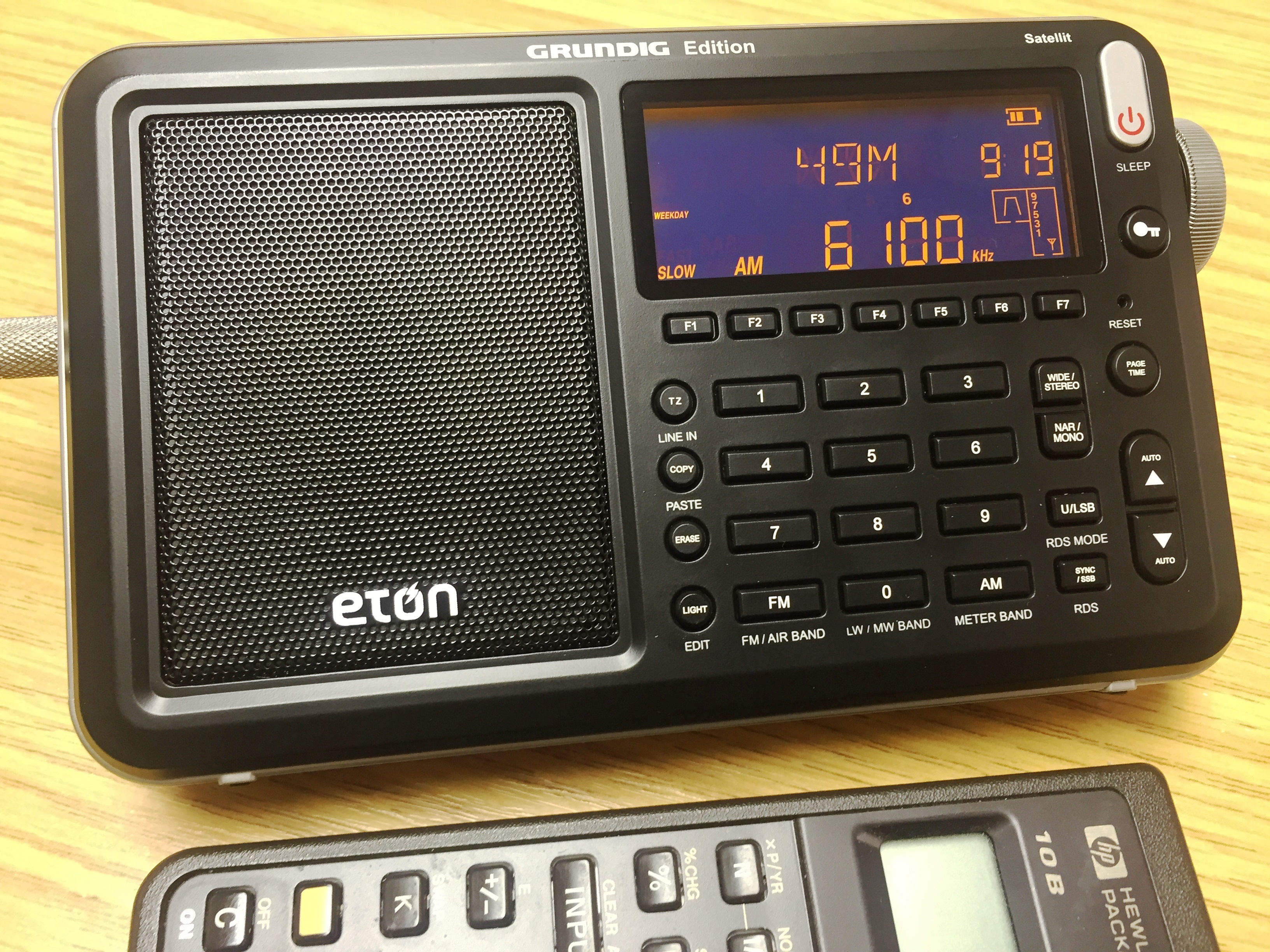
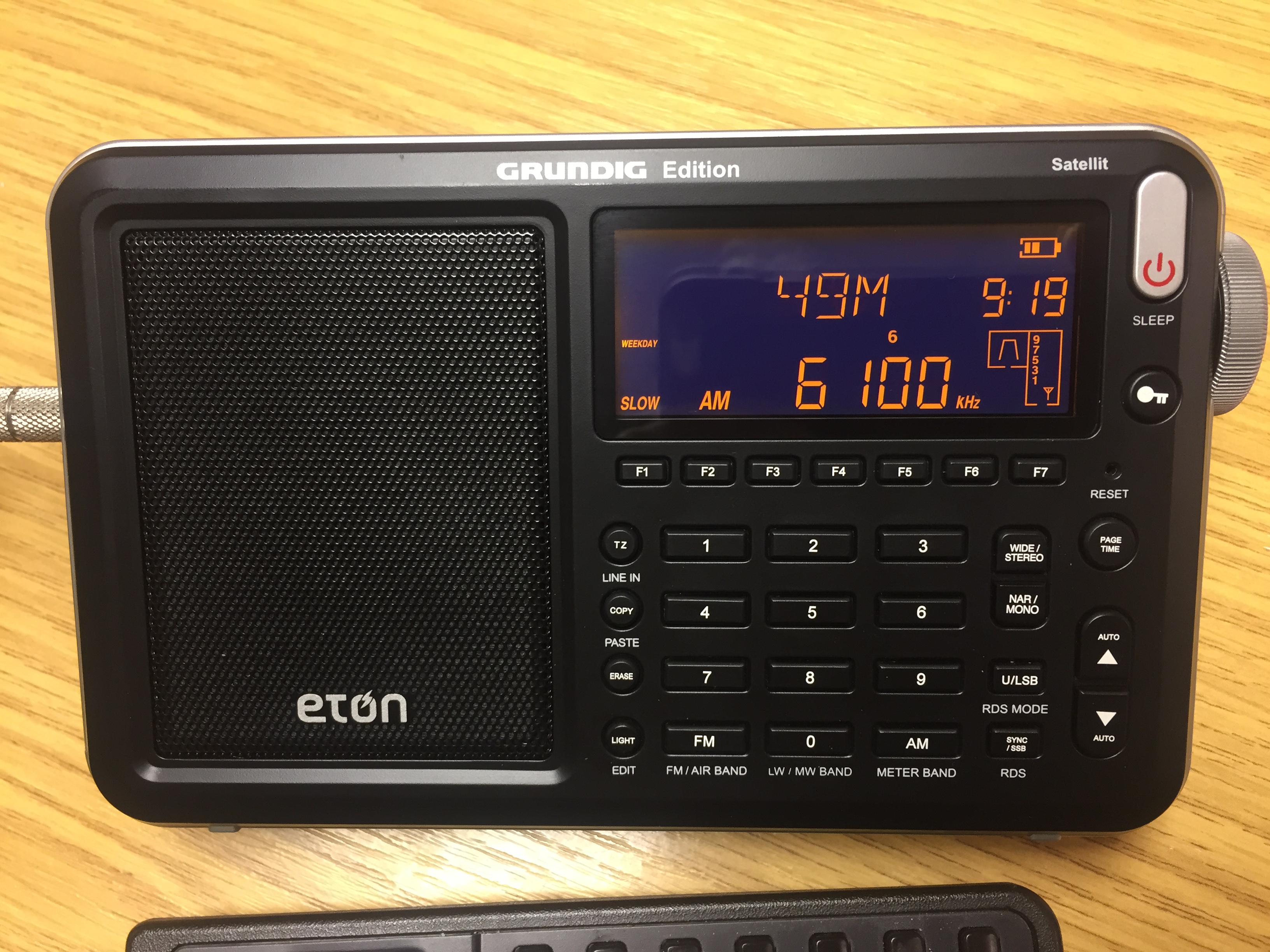
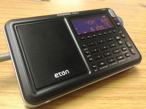
Even though the poster himself suggested the Eton might not be classified as a classic Satellit, it’s interesting to note that another DXer with three decades of experience and someone who’s owned the Satellit 400, 500 and 700 models concluded the opposite and that for various reasons, the newest Satellit is a far better performer with weak DX than those vintage receivers ever were. In his experience, the classic Satellit receivers always delivered excellent audio and thus were brilliant for listening to international broadcasters. However, for weak DX the Satellit 500 didn’t perform as well as the budget Sangean ATS-803A and the ICF-2001D wiped the floor with the 700. So, is the Eton worthy of the Satellit branding? Perhaps the problem is it’s just so small – I mean compared to the Satellit 800….you could confuse the Eton to be it’s remote control – if it had one! It is diminutive and I’ve purposely taken a picture of it with my calculator to demonstrate this. It’s actually not much bigger than the Tecsun PL-310ET, so in terms of form-factor, definitely a departure from Satellits of the past.
What about performance? I tested the Eton at the woods I use for DXing, with a 50 metre longwire. In the space of a couple of hours, I’d recorded ABC Northern Territories on 2325, 2485 and 4835 kHz, Pyongyang BS, North Korea on 3320 kHz, Angola on 4950 kHz, Guinea on 9650 kHz and a weak signal from the Solomon Islands on 5020 kHz. The signals from ABC on 2485 kHz, Angola and Guinea were stronger and clearer than I’d ever heard previously. Pyongyang on 3320 kHz and the Solomon Islands were personal firsts.
The Eton performed way beyond my expectations and I hope this post will go some way to restoring the repuation of this brilliant little radio, which in my opinion fully deserves to be called a Satellit. More testing is necssary, including direct comparisons with other receivers – all of that to come in due course. Text links and embedded reception videos follow. Thanks for reading/watching/listening and I wish you all great DX!
- The Eton Satellit; is it any good? Let’s start with ABC Northern Territories on 120 metres…
- The Eton Satellit; is it any good? Rádio Nacional de Angola 4950 kHz…wonderfully clear
- The Eton Satellit; is it any good? Moving on to ABC Northern Territories 2325 kHz…
- The Eton Satellit, First reception of Solomon Islands BC, 5020 kHz (requires headphones)
- The Eton Satellit; Radio Guinée 9650 kHz Conakry, Guinea, armchair copy
- The Eton Satellit: Pyongyang Broadcasting Station 3320 kHz, North Korea
Click here to view on YouTube.
Click here to view on YouTube.
Click here to view on YouTube.
Click here to view on YouTube.
Click here to view on YouTube.
Click here to view on YouTube.
Clint Gouveia is the author of this post and a regular contributor to the SWLing Post. Clint actively publishes videos of his shortwave radio excursions on his YouTube channel: Oxford Shortwave Log. Clint is based in Oxfordshire, England.