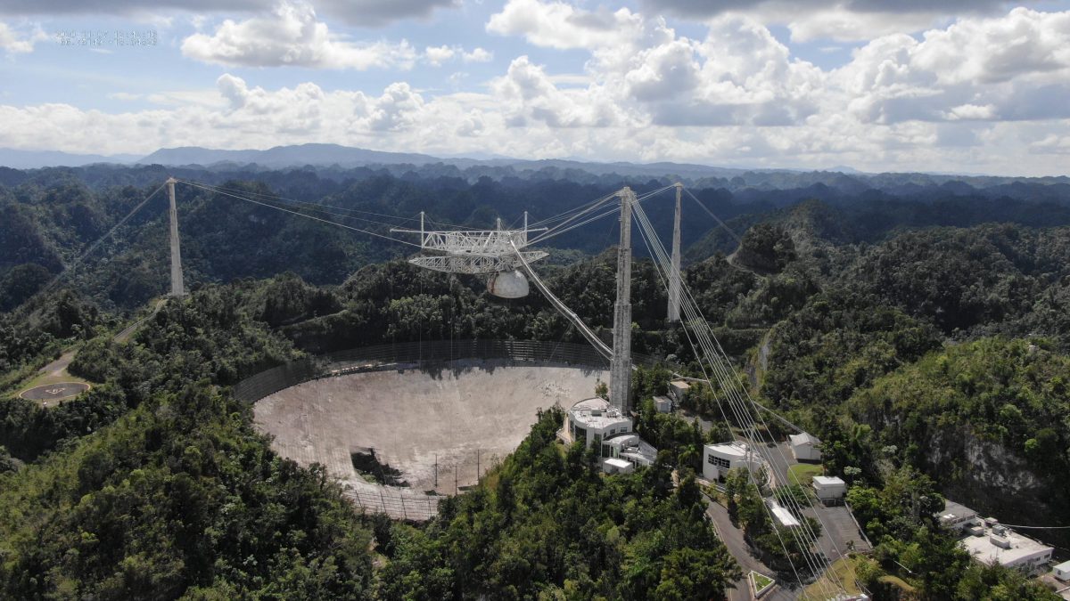
Category Archives: Ham Radio

How to properly install a Mini Whip antenna in an noisy urban environment

Many thanks to SWLing Post contributor, Grayhat, who shares the following guest post:


Setting up a Mini Whip antenna

by Grayhat

I’ve been fiddling with my “balcony antenna” experiment for quite a while now, and I settled with a Linear Loaded Dipole (LLD, also known as “Cobra”) which, in my case, due to self-imposed limitations was a short one (about 9m total).

Since I mentioned it, here is a pic of the antenna showing its installation:

Click images to enlarge.

In the above image you can see the overall setup of the LLD, the modification I did, by adding additional wires to the end of the arms and also the Mini Whip location

The LLD served me well, from LW up to around 200MHz allowing me to listen to broadcasters, hams, aircraft communications, time signals and then more, and it’s definitely a keeper, but I wanted to give a try to the “Mini Whip” antenna, even if a lot of people discard it saying it’s a noisy antenna and not worth it; keep in mind the Utwente SDR uses it and it seems to work fine, so I had to give it a try !

Anyhow, after searching the internet for a suitable whip, I finally found this one:

I bought the antenna on Amazon, but it’s also available on eBay and while the price isn’t the lowest one, I chose it since it uses BNC connectors only (some models use a mix of UHF/BNC or the like). This one had a top wing nut allowing to connect an additional (optional) external whip (may be useful on lower bands) and, last but not least, its color; being gray, it is quite stealth, which may be useful for some people (not my case, luckily). So I went on and ordered the antenna, the delivery took about 10 days and the package contents were exactly as shown above. The supplied coax is thin (RG-174 I believe) and it would be a good idea replacing it with some runs of RG-58, but for the sake of the experiment, I used the original wire.

So, having the antenna, I looked around for informations about the correct installation for the “Mini Whip” and found that in most cases, the reported poor performances of the Mini Whip are due to people installing it the wrong way. For reference and information about how the whip works and about how to properly install it, please refer to the information from PA3FWM found here and here.

Now, if you can place the whip in a garden or yard, using a pole, the correct installation of the whip is the one shown in this pic:

If you carefully look at the image you will notice that the whip sits above the supporting (metallic) pole and that the ground of the connector is electrically connected to the pole (through the clamp). Plus, the pole is then grounded (at the bottom) and the coax (which has chokes) runs away from the metallic pole.

What does the above mean ? Well, the Mini Whip antenna needs a “counterpoise” (ground) to work, and installing it as above, instead of using the coax braid as its counterpoise, the Mini Whip will use the supporting pole, this helps a lot minimizing the noise and it’s one of the tricks for a proper setup, the other one is placing the whip as far away from the “noise cloud” of your home as possible. In my case, I choose the far end of the balcony–also since I had a nice support there, the image below shows the whip installation using a piece of PVC pipe I bought at a nearby home improvement store:

At first, I just installed the antenna without the ground wire and with the coax coming down vertically from the connector. When I compared the whip to my LLD, the results were discouraging: the noise floor was much higher and a lot of signals, which the LLD received without problems, totally disappeared inside the noise floor.

Being the kind of hard-headed guy I am (and having read the documentation about proper setup) I went on and made further modifications.

Let me detail the installation a bit better with this first image (click to enlarge):

As you can see in the above image, the whip is supported by a piece of PVC pipe which keeps it above the metal fencing of the balcony (or a support pole if you’ll use it) and I also connected a short run of insulated wire to the ground of BNC plug at the bottom of the whip. This short run goes to a wire clamp which allows it to connect to the “counterpoise” (ground) wire.

In my case, since the balcony was at 2nd floor, I didn’t have a way to give to the antenna a real ground, so I decided to run a length of wire (AWG #11) down the pipe and then along my balcony fencing (10m total). An alternative, which will also work for roof installations, would be using chicken wire (fencing). In such a case, you may lay as much chicken wire as you can on the floor/roof and connect the wire coming down from the whip ground to it. I haven’t that that (yet!) but I think it may further lower the noise and improve performances.

Notice that in the case of the Utwente Mini Whip, the antenna support pole is connected to metallic roofing so it has plenty of (virtual) ground.

Later on, I improved the setup by raising the antenna a bit more and routing the wire (almost) horizontally from the feedpoint to reduce coupling with the vertical “counterpoise” wire.

The image below shows the final setup:

While not visible in the above image, I also wrapped the coax wire in a loop at the point where it’s held by the fencing and added some snap-on chokes to the coax at the point where it enters the building.

With all the modifications in place, the antenna started performing as it was designed to. The noise floor is still a bit higher than the one of the LLD, but given that it’s an active antenna, that’s to be expected

To give you an idea of the signals and noise floor, here are a couple of images taken from the screen of my laptop while running SDRuno. The first one shows the waterfall for the 40m band

While the second one, below, shows the one for the 80m band:

At any rate, my usual way of testing antenna performance (and modifications effects), aside from some band scanning/listening, is to run an FT8 session for some hours (and optionally repeat it over some days) and then check the received spots.

In the case of the Mini Whip, after all the modification to the setup, I ran an FT8 session using JTDX for some hours and the images below show the received spots. The first image shows the whole map of the received stations:

While the second one below is a zoom into the European region to show the various spots picked up there; the different colors indicate the 20m (yellow), 40m (blue/violet) and 80m (violet) bands:

As you can see, the Mini Whip performed quite well despite the “not exactly good” propagation.

While some time ago I’d have discarded the Mini Whip as a “noise magnet”, as of today, with a proper installation, I think it’s a keeper. While it can’t be compared to bigger antennas, I believe it may be a viable antenna for space-constrained situations. The only thing it needs is a bit of care when setting it up to allow it to work as it has been designed to.


Brilliant job, Grayhat! Thank you so much for sharing your experience setting up the Mini Whip antenna. As you stated, so many SWLs dismiss the Mini Whip as “noisy”–but with a proper ground, it seems to perform rather well. The benchmark example of a Mini Whip’s performance must be the U Twente Web SDR

Thank you again, Grayhat! 

Spread the radio love

Icom IC-705 blind audio tests: Let’s take a look at your choices!

Before I had even taken delivery of the new Icom IC-705 transceiver, a number of SWLing Post readers asked me to do a series of blind audio comparison tests like I’ve done in the past (click here for an example).

Last week, I published a series of five audio tests/surveys and asked for your vote and comments. The survey response far exceeded anything I would have anticipated.

We received a total of 931 survey entries/votes which only highlights how much you enjoy this sort of receiver test.

In this challenge, I didn’t even give you the luxury of knowing the other radios I used in each comparison, so let’s take a look…

The competition

Since the Icom IC-705 is essentially a tabletop SDR, I compared it with a couple dedicated PC-connected SDRs.

WinRadio Excalibur SDR

The WinRadio Excalibur

I consider the WinRadio Excalibur to be a benchmark sub $1000 HF, mediumwave, and longwave SDR.

It is still my staple receiver for making off-air audio and spectrum recordings, and is always hooked up to an antenna and ready to record.

In the tests where I employed the WinRadio Excalibur, I used its proprietary SDR application to directly make recordings. I used none of its advanced filters, AGC control, or synchronous detection.

Click here to read my original 2012 review of the WinRadio Excalibur.

Airspy HF+ SDR

The Airspy HF+ SDR

I also consider the Airspy HF+ SDR to be one of the finest sub-$200 HF SDRs on the market.

The HF+ is a choice SDR for DXing. Mine has not been modified in any way to increase its performance or sensitivity.

In the test where I employed the HF+ I used Airspy’s own SDR application, SDR#, to directly make recordings. I used none of its advanced filters, AGC control, noise reduction, or synchronous detection.

Belka-DSP portable receiver

The Belka-DSP

I recently acquired a Belka-DSP portable after reading 13dka’s superb review.

I thought it might be fun to include it in a comparison although, in truth, it’s hardly fair to compare a $160 receiver with a $1300 SDR transceiver.

The Belka, to me, is like a Lowe HF-150 in a tiny, pocket package.

Elecraft KX3 QRP transceiver

The Elecraft KX3

The KX3 is one of the best transceivers I’ve ever owned. Mine has the CW roofing filter installed (only recently) and is, without a doubt, a benchmark performer.

Click here to read my full review.

If you check out Rob Sherwood’s receiver test data table which is sorted by third-order dynamic range narrow spaced, you’ll see that the KX3 is one of the top performers on the list even when compared with radios many times its price. Due to my recording limitations (see below) the KX3 was the only other transceiver used in this comparison.

Herein lies a HUGE caveat:

The WinRadio application

As I’ve stated in SDR reviews in the past, it is incredibly difficult comparing anything with PC-connected SDRs because they can be configured on such a granular level.

When making a blind audio test with a stand-alone SDR radio like the IC-705–which has less configurability–you’re forced to take one of at least two paths:

  • Tweak the PC-connected SDR until you believe you’ve found the best possible reception audio scenario and use that configuration as a point of comparison, or
  • Attempt to keep the configuration as basic as possible, setting filters widths, AGC to be comparable and turning off all other optional enhancements (like synchronous detection, noise reduction, and advanced audio filtering to name a few).

I chose the latter path in this comparison which essentially undermines our PC-connected SDRs. Although flawed, I chose this approach to keep the comparison as simple as possible.

While the IC-705 has way more filter and audio adjustments than legacy transceivers, it only has a tiny fraction of those available to PC-connected SDRs. Indeed, the HF+ SDR, for example, can actually be used by multiple SDR applications, all with their own DSP and feature sets.

In short: don’t be fooled into thinking this is an apples-to-apples comparison. It is, at best, a decent attempt at giving future IC-705 owners a chance to hear how it compares in real-word live signals.

Recordings

The Zoom H2N connected to my Elecraft KX2.

Another limiting factor is that I only have one stand-alone digital audio recorder: the Zoom H2N. [Although inspired by Matt’s multi-track comparison reviews, I plan to upgrade my gear soon.]

The IC-705 has built-in digital audio recording and this is what I used in each test.

The WinRadio Excalibur and Airspy HF+ also have native audio recording via their PC-based applications.

With only one stand-alone recorder, I wasn’t able to simultaneously compare the IC-705 with more than one other stand-alone receiver/transceiver at a time.

As I mentioned in each test, the audio levels were not consistent and required the listener to adjust their volume control. Since the IC-705, Excalibur, and HF+ all have native recording features, the audio levels were set by their software. I didn’t post-process them.

Blind Audio Survey Results

With all of those caveats and disclaimers out of the way, let’s take a look at the survey results.

Blind audio test #1: 40 meters SSB

In this first test we listened to the IC-705, WinRadio Excalibur, and Belka-DSP tuned to a weak 40 meter station in lower sideband (LSB) mode. Specifically, this was ham radio operator W3JPH activating Shikellamy State Park in Pennsylvania for the Parks On The Air program. I chose this test because it included a weak station calling CQ and both weak and strong stations replying. There are also adjacent signals which (in some recordings) bleed over into the audio.

Radio A: The Belka-DSP

Radio B: The WinRadio Excalibur

Radio C: The Icom IC-705

Survey Results

The Icom IC-705 was the clear choice here.

Based on your comments, those who chose the IC-705 felt that the weak signal audio was more intelligible and that signals “popped out” a bit more. Many noted, however, that the audio sounded “tinny.”

A number of you felt it was a toss-up between The IC-705 and the Belka-DSP. And those who chose the WinRadio Excalibur were adamant that is was the best choice.

The WinRadio audio was popping in the recording, but it was how the application recorded it natively, so I didn’t attempt to change it.

Test #2: 40 meters CW

Icom IC-705In this second test we listened to the Icom IC-705 and the Elecraft KX3 tuned to a 40 meter CW station.

Radio A: Icom IC-705

Radio B: Elecraft KX3

Survey Results

The Elecraft KX3 was preferred by more than half of you.

Based on your comments, those who chose the KX3 felt the audio was clearer and signals had more “punch.” They felt the audio was easier on the ears as well, thus ideal for long contests.

Those who chose the IC-705, though, preferred the narrower sounding audio and felt the KX3 was too bass heavy.

Test #3: Shannon Volmet SSB

In this third test we listened to the Icom IC-705 and WinRadio Excalibur, tuned to Shannon Volmet on 8,957 kHz.

Radio A: WinRadio Excalibur

Radio B: Icom IC-705

Survey

The Icom-705 audio was preferred by a healthy margin. I believe, again, this was influenced by the audio pops heard in the WinRadio recording (based on your comments).

The IC-705 audio was very pleasant and smooth according to respondents and they felt the signal-to-noise ratio was better.

However, a number of comments noted that the female voice in the recording was actually stronger on the WinRadio Excalibur and more intelligible during moments of fading.

Test #4: Voice of Greece 9,420 kHz

In this fourth test we listen to the Icom IC-705, and the WinRadio Excalibur again, tuned to the Voice of Greece on 9,420 kHz.

Radio A: Icom IC-705

Radio B: WinRadio Excalibur

Survey

While the preference was for the IC-705’s audio (Radio A), this test was very interesting because those who chose the Excalibur had quite a strong preference for it, saying that it would be the best for DXing and had a more stable AGC response. In the end, 62.6% of 131 people felt the IC-705’s audio had slightly less background noise.

Test #5: Radio Exterior de España 9,690 kHz

In this fifth test we listened to the Icom IC-705, and AirSpy HF+, tuned to Radio Exterior de España on 9,690 kHz. I picked REE, in this case, because it is a blowtorch station and I could take advantage of the IC-705’s maximum AM filter width of 10 kHz.

Radio A: Icom IC-705

Radio B: Airspy HF+

Survey

The IC-705 was preferred by 79% of you in this test.

Again, very interesting comments, though. Those who preferred the IC-705 felt the audio simply sounded better and had “punch.” Those who preferred B felt it was more sensitive and could hear more nuances in the broadcaster voices.

So what’s the point of these blind audio tests?

Notice I never called any radio a “winner.”

The test here is flawed in that audio levels and EQ aren’t the same, the settings aren’t identical, and even the filters have slightly different shapes and characteristics.

In other words, these aren’t lab conditions.

I felt the most accurate comparison, in terms of performance, was the 40M CW test with the KX3 because both employed similar narrow filters and both, being QRP transceivers, are truly designed to perform well here.

I essentially crippled the WinRadio Excalibur and Airspy HF+ by turning off all all but the most basic filter and AGC settings. If I tweaked both of those SDRs for optimal performance and signal intelligibility, I’m positive they would have been the preferred choices (indeed, I might just do another blind audio test to prove my point here).

With that said, I think we can agree that the IC-705 has brilliant audio characteristics.

I’ve noticed this in the field as well. I’m incredibly pleased with the IC-705’s performance and versatility. I’ll be very interested to see how it soon rates among the other transceivers in Rob Sherwood’s test data.

The IC-705 can actually be tailored much further by adjusting filter shapes/skirts, employing twin passband tuning and even using its noise reduction feature.

If anything, my hope is that these blind audio tests give those who are considering the Icom IC-705 a good idea of how its audio and receiver performs in real-word listening conditions.


Do you enjoy the SWLing Post?

Please consider supporting us via Patreon or our Coffee Fund!

Your support makes articles like this one possible. Thank you!

Spread the radio love

Radio Waves: Free Download of Equinox E-book, Pop Shop Radio, Hamcation Postponed, and “Radio Ga Ga” Salutes Radio Pioneers

Radio Waves:  Stories Making Waves in the World of Radio

Because I keep my ear to the waves, as well as receive many tips from others who do the same, I find myself privy to radio-related stories that might interest SWLing Post readers.  To that end: Welcome to the SWLing Post’s Radio Waves, a collection of links to interesting stories making waves in the world of radio. Enjoy!

Many thanks to SWLing Post contributors DM Barrett, Tracy Wood, Mike Terry, and the Southgate ARC for the following tips:


EQUINOX – Free Download (D.M. Barrett)

EQUINOX, DM Barrett’s best seller that blends science fiction with amateur radio and shortwave, can be downloaded FREE in eBook format from Amazon on the following dates:

Thursday, October 22, 2020;
Thursday, November 5, 2020;
Thursday, November 12, 2020;
Thursday, November 26, 2020; and,
Thursday, December 10, 2020.

N4ECW’s EQUINOX, as well as his other novels, can be obtained at Amazon and Barnes & Noble.

The audiobook versions are available at audible.com and iTunes.

Broadcasting from Hope, on shortwave radio (Hope Standard)

Tony Pavick combines love for music and radio in weekly show, Pop Shop Radio

While he may not be jumping up and down in a radio booth throwing records on turntables, Tony Pavick is once again pumping out radio in the form of a weekly hour-long show from his home in Hope.

It’s been 20 years since radio was broadcast from Hope – former radio personality and now fire chief Tom DeSorcy confirmed that CKGO, Hope’s AM radio station, closed its doors in 2000. And while Pavick isn’t starting a new radio station, he’s broadcasting for an hour each week from Hope to the world via shortwave radio.

Shortwave, a band in between the AM and FM band, Pavick explained, was utilized right up until the 1990s by countries wanting to spread their news, propaganda and cultural content. Living in the U.S., Pavick got his first taste of Canada while listening to Radio Canada International on a shortwave radio his parents bought him in the late 1960s.

Since the end of the Cold War, Pavick explains, countries have turned their radio equipment over to different groups. One of those is Channel 292 at the University of Twente, where he broadcasts at a rate of 15 Euro for an hour of radio time. Those without the ability to pick up shortwave can listen to Pavick’s show online at websdr.ewi.utwente.nl:8901/?tune=6070am.

The show starts with radio static, followed by the sound of a pop being opened and poured. Then Pavick comes in with “from the town of Hope in super natural British Columbia, in Canada, I’m Tony and this is Pop Shop Radio.”

Pavick plays a wide range of pop music, for example his first show included a Czech language version of Heart of Glass recorded when Czechoslovakia was still a nation, and a 2006 Groovefinder remix of Nina Simone’s Ain’t Got No.

He draws inspiration from a time when you could hear, on a top 40 station, a line-up featuring Jefferson Airplane, followed by Johnny Cash and then the The Beatles. “There was a great variety of music played on the same station,” he said. “Popular music wasn’t just rock n’ roll, it was rock and pop and country and just a whole variety of things. So that’s where the idea for it being called the Pop Shop came about.”

Pavick doesn’t keep it a secret where he finds some of the more obscure plays. He uses music website 45cat.com, an extensive online music archive.[]

Orlando HamCation postponed (Southgate ARC)

As the world’s second largest hamfest, we pride ourselves on delivering a high-quality event to our attendees and would not want to put on a show that is anything less than what the ham radio community deserves.

After much deliberation, the difficult decision to postpone the 75th Orlando HamCation was made. It is with heavy hearts that we must make this decision. We had wished to see all of you next year in person, but the situation we face globally has made this challenging. Instead, HamCation will be moved to February 11-13th, 2022. We are looking to host some unique Webinars, a QSO Party and possibly Prize Drawings for 2021.

More information to come on our website soon.
For those who have already purchased tickets and spaces, we will be in contact with you shortly and will reach out to you directly. You will have the option to use your ticket for HamCation 2022, receive a refund or donate the funds to the Orlando Amateur Radio Club.

We thank all of you for your patience and understanding during these times and are excited to see you all again in 2022…

73, Michael Cauley, W4MCA
General Chairman
Orlando HamCation

For more details see: https://www.hamcation.com
http://www.arrl.org/news/arrl-national-convention-and-orlando-hamcation-postponed-to-february-2022
Also, check the ARRL Letter for October 8th, 2020:
http://www.arrl.org/arrlletter?issue=2020-10-08

Radio Ga Ga: Aberdeen author creates new work to salute the pioneers of the airwaves (The Press and Journal)

Gordon Bathgate can barely recall a time when he wasn’t in thrall to the radio and marvelling at all the different sounds which came out of a magic box in his living room when he was growing up in the north-east of Scotland.

A lot of snap, crackle and pop music has come and gone since these early days, but he is still Radio Ga Ga about an invention which has shaped all our lives and is celebrating its centenary in 2020.

This follows the innovation and imagination of so many pioneering figures, including his compatriot James Clerk Maxwell, Heinrich Hertz and Guglielmo Marconi, whose name has become inextricably linked with the device.

In so many different ways, Mr Bathgate, who has written a new book, Radio Broadcasting: A History of the Airwaves, has devoted decades to boosting its profile in many guises.

He was a founding member of Grampian Hospital Radio at Aberdeen Royal Infirmary – a service which does invaluable work and particularly in the current Covid-induced social isolation.

He also presented shows for North East Community Radio at Kintore and presents music programmes as far afield as Peterhead, The Netherlands and the fabled Radio Caroline.

He has created a series of witty little films, imparting his love for the Doric language, including pastiches of Star Trek and Dallas.

But it’s his passion for radio which shines through the pages of his new production.[]


Do you enjoy the SWLing Post?

Please consider supporting us via Patreon or our Coffee Fund!

Your support makes articles like this one possible. Thank you!

Spread the radio love

Steve builds a DC30B QRP Transceiver

DC30B QRP Transceiver ProjectMany thanks to SWLing Post contributor, Steve (KZ4TN), who shared the following guest post originally on QRPer.com, but I’ve posted it here as well because I’m sure it’ll resonate with those of us who love building kits!:


DC30B QRP Transceiver Project

by Steve Allen, KZ4TN

I wanted to build a lightweight backpackable transceiver I could take hiking and camping. I chose the 30 meter band as it is specific to CW and the digital modes. I am also in the process of building Dave Benson’s (K1SWL) Phaser Digital Mode QRP Transceiver kit for the 30 meter band. Also, a 30 meter antenna is a bit smaller than one for 40 meters and the band is open most anytime of the day.

I sourced the DC30B transceiver kit, designed by Steve Weber KD1JV, from Pacific Antennas, http://www.qrpkits.com. It appears that they are now (10-11-20) only offering the kit for the 40 meter band. The following information can be used for the assembly of most any kit that lacks an enclosure.

Lately I have been finding extruded aluminum enclosures on Amazon.com and eBay.com. They come in many sizes and configurations. I like to use the versions with the split case which allows you to access the internal enclosure with the front and rear panels attached to the lower half of the enclosure. Most of these enclosures have a slot cut into the sides that allow a PCB to slide into the slots keeping it above the bottom of the enclosure without having to use standoffs. The one requirement for assembly is that the PCB needs to be attached to either the front or rear panel to hold it in place.

DC30B QRP Transceiver Project

As the enclosure is anodized, I didn’t want to rely on the enclosure for common ground. I used a piece of copper clad board that I cut to fit the slot width of the enclosure and attached it to the back panel. I was then able to mount the transceiver PCB to the copper clad board with standoffs. This basic platform of the enclosure with the copper clad PCB provides a good foundation for any number of projects. All you have to do is mount the wired PCB on the board, install the components on the front and rear panel, then wire it up.

DC30B QRP Transceiver Project

I wanted to have the choice of a few frequencies to operate on so I searched eBay for 30 meter crystals and found a source for 4 different popular frequencies. I installed a rotary switch on the front panel and added a small auxiliary PCB with two, 4 pin machined IC sockets. This allowed me to plug the crystals into the sockets. I wired the bottom of the socket PCB first using wire pairs stripped from computer ribbon cable leaving extra length. I marked the wires with dots to indicate which sockets each wire pair went to so I could solder them onto the rotary switch in the correct order. It was tight but I always work with optical magnification so I can see exactly what I’m doing. I have used this crystal switching method in the past with good success.

DC30B QRP Transceiver Project

DC30B QRP Transceiver ProjectThe rest of the assembly was straight forward. I find that most kits are well designed and documented, and if you take your time and follow the directions carefully all should go well. The two most common speed bumps seem to be soldering in the wrong component or bad soldering technique. I double check all component values and placements prior to soldering, and I always use optical magnification while working. I inspect each solder joint and look for good flow through in the plated through holes, and make sure there are no solder bridges.

DC30B QRP Transceiver Project

DC30B QRP Transceiver ProjectThe finished product. I bought a Dymo label maker and it works very well for projects like this. I love using these enclosures and they are a leap forward from the old folded aluminum clam shells I used in the past. I could stand on this without causing any damage. Power out is 1-3 watts depending on the DC power in. The receiver is sensitive and the ability to choose from four frequencies is a real plus.

73 de KZ4TN

Steve Allen
Elizabethton, TN


Gorgeous work there, Steve! Thank you for sharing!

Spread the radio love

How to install a mechanical SSB filter on the Yaesu FRG-7

Many thanks to SWLing Post contributor, Kostas (SV3ORA), for sharing the following guest post which originally appeared on his radio website:


How to install a mechanical SSB filter on the Yaesu FRG-7

by Kostas (SV3ORA)

The Yaesu FRG-7 is a general coverage MW/SW receiver that uses the Wadley Loop system for stabilizing the frequency tuning. The receiver has a good sound on AM mode, that reminds me the tube receivers sound. However, on sideband mode, it is pretty much useless. The IF ceramic filter that is used, does not have enough selectivity to reject the opposite sideband. No matter if the front panel mode selector switch states USB/CW and LSB, these just shift the BFO, nothing more. The receiver is a DSB set not SSB. A cheap way you can accomplish single signal sideband reception with the FRG-7 is described in this link. Whereas it works, it increases the audio bandwidth of the signals to the high pitch.

A better approach is to install an additional mechanical filter to the receiver. This of course requires expensive 455KHz mechanical filters, but if you have one in hand or if you are willing to pay for the improvement in performance, then this is the recommended option. But you can’t just desolder the ceramic filter of the receiver and solder a mechanical filter in place. On AM mode, you need wider bandwidth, but on SSB mode you need narrower. So both filters must be in place and a selection must be done in each mode. Thankfully, this modification is pretty easy on the FRG-7 and it does not require any modification of the external appearance of the radio.

The schematic of the FRG-7 is shown above. Everything with red color, are part of the modification. The modification is pretty straight forward. You have to desolder the original ceramic filter from the FRG-7 PCB and install it on a separate PCB along with the new 455KHz mechanical filter. To select between the two filters, a 9-12v DPDT relay can be used and it must be connected as shown in the schematic. The power for the relay coil is derived from one section of the mode switch (S3d). On USB or LSB modes, the BFO is energized and this power is also used to energize the relay, which in turn switches to the narrow mechanical filter on these modes.

A good place for the new PCB that accommodates the filters, is just below the main tuning dial of the receiver. There is a hole there and three screws, which can be used to also hold this PCB in place. I needed to replace these screws in mine with longer ones, because I used spacers to prevent the PCB from touching the chassis. But this is optional.

Two small pieces of coaxial cables are used to connect the new PCB to the pads of the ceramic filter, that has been now removed from the original PCB of the receiver. Ground these cables on both ends.

The power cables for the relay coil (shown with red and black in the picture above), are passed below the PCB to the chassis opening and through a hole to the bottom of the original PCB of the receiver. The ground wire is soldered to the filter ground point and the red wire is soldered to the mode selector switch S3d. S3d is the outer wafer onto the switch. Use a multimeter to find the contact of the switch that has VCC when the mode is switched to USB or LSB. This is the point where you want to connect the red wire.

After installing everything, you should perform an alignment of the TC404 and the T406 in the BFO section as described in the manual. This requires a frequency counter, but I did my alignment by simply adjusting the two controls by ear, until I got roughly the same pitch on LSB and SSB audio bandpass. These controls interact, so you have to do a bit of back and forth in both of them. It is very easy.

After installing the modification and aligning the receiver, the result is pretty obvious. No more DSB reception, SSB signals are received just once in the dial and their bandwidth is limited as it should on SSB. The mechanical filter I had, was a bit narrow (2.1KHz) so I can also hear a bit os “seashell” sound on SSB, but SSB voice signals are perfectly understood. It is interesting that the audio volume between the ceramic filter and the mechanical filter was just about the same, which indicates that there is no additional loss in the newly installed filter. Another interesting thing is that there was no need for any impedance matching using active devices or transformers on the mechanical filter. It worked just by directly connecting it. Neither it’s loss, not it’s response seems to be affected by any possible impedance mismatches.

Note that Collins produced both symmetrical and asymmetrical mechanical filters (yes they used two filters, one for USB and one for SSB in some of their gear). My filter is a symmetrical one (same roll-off response curve on both sides of the filter passband). If you use an asymmetrical filter, expect a bit different pitch when switching from LSB to USB and vice versa. Not a huge problem, but just a note.

By performing this simple modification, you will end up with an FRG-7 receiver that is trully selective, allowing for real SSB reception. Most importantly you do not ruin the appearance of your precious FRG-7, but just improving it’s performance. This modification would probably be appreciated much when deciding to sell your FRG-7 to someone else.


Thank you for sharing this practical and affordable project with us, Kostas!

Post Readers: Check out this project and numerous others on Kostas’ excellent website.

Spread the radio love

Icom IC-705 Blind Receiver Test #5 (Final Test)

Test #5: Radio Exterior de España 9,690 kHz

In this test (click here for #1here for #2, here for #3, and here for #4) we’ll listen to the Icom IC-705, and one other comparable radio, tuned to Radio Exterior de España on 9,690 kHz. I picked REE, in this case, because it is a blowtorch station and I could take advantage of the IC-705’s maximum AM filter width of 10 kHz.

I’ve done my best to match these radios in terms of audio and receiver settings, but it’s certainly not perfect–these are essentially real world, not laboratory conditions.

Notes:

  • Both radios are using the same antenna via my ELAD ASA15 Antenna Splitter Amplifier
  • Both radios are set to the same bandwidth: 10 kHz
  • I’ve tried to match AGC settings on all radios
  • Both radios have different audio EQ characteristics–not all are fully adjustable
  • Both have separate recording devices and are not matched perfectly in terms of audio levels. In other words, you may need to adjust your volume a bit to compare.

My advice would be to focus on aspects like signal intelligibility, selectivity and signal to noise.

Please listen to each recording, then kindly answer and submit the survey below. Thank you!

Radio A

Radio B

Survey

Spread the radio love

Icom IC-705 Blind Receiver Test #4

Test #4: Voice of Greece 9,420 kHz

In this second test (click here for #1, here for #2, and here for #3) we’ll listen to the Icom IC-705, and one other comparable radio, tuned to the Voice of Greece on 9,420 kHz.

I’ve done my best to match these radios in terms of audio and receiver settings, but it’s certainly not perfect–these are essentially real world, not laboratory conditions.

Notes:

  • Both radios are using the same antenna via my ELAD ASA15 Antenna Splitter Amplifier
  • Both radios are set to the same bandwidth
  • I’ve tried to match AGC settings on all radios
  • Both radios have different audio EQ characteristics–not all are fully adjustable
  • Both have separate recording devices and are not matched perfectly in terms of audio levels. In other words, you may need to adjust your volume a bit to compare.

My advice would be to focus on aspects like signal intelligibility, selectivity and signal to noise.

Please listen to each recording, then kindly answer and submit the survey below. Thank you!

Radio A

Radio B

Survey

Spread the radio love