Shortwave listening and everything radio including reviews, broadcasting, ham radio, field operation, DXing, maker kits, travel, emergency gear, events, and more
Many thanks to SWLing Post contributor, Pedro Andrade, who writes:
Hi Thomas!
I’m a noob when it comes to DXing, I only got into the hobby late 2020, and I got to say: I’m hooked. So, sooner or later, I would hit your website/blog. For that, and the continued work in every aspect of the hobby (technical issues, tips, tricks, schedules, etc), I thank you from a noob perspective and from someone that believes the internet is beautiful when it comes to sharing and getting communities together.
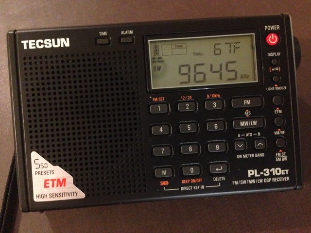
That said […]the reason for writing this email, is that I found out that the ETM scan could be very much improved on the Tecsun PL-310et (and I think others).
You simply change the filter sensitivity prior to the scan: the higher the filter the lower the sensitivity. The lower the filter (1 kHz) the higher the sensitivity and thus more stations caught by the scan.
I hope you find this useful and worth sharing for your readers.
Thanks again for the continued work on the radio side of things.
Regards, Pedro.
What a brilliant tip, Pedro! Thank you for sharing and also for demonstrating in your video! Also, thank you for the kind words about the SWLing Post–an amazing community of folks like you and a pure labor of love!
Many thanks to SWLing Post contributor, Jock Elliott (KB2GOM), who shares the following guest post:
Really cool trick the CCrane Skywave SSB will do — the “radio butler”?
To paraphrase Ratty from Wind in the Willows: ” “Believe me, my young friend, there is nothing–absolutely nothing–half so much worth doing as simply messing about with radios.”
That is precisely what I was doing . . . messing, simply messing about with the CCrane Skywave SSB.
Then I observed something. Just above the LIGHT button is some lettering: “ATS.” Not having taken notice of it before, I looked it up in the manual. It stands of Automatic Tuning System, and the manual says this about it:
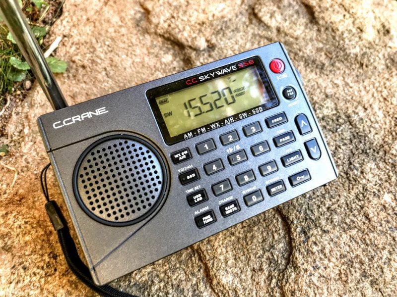
“This feature programs all receivable stations in the AM, FM, Air and Shortwave bands to memory buttons. To use ATS, select your desired band: AM, FM, Air or Shortwave, and press and hold the ATS button for two seconds. The CCrane Skywave SSB will scan the entire band and automatically set all available stations in sequence 1-20. If more than stations are available, then the remaining stations will be preset to the next memory page, and so on.”
So I tried it; I punched in a shortwave frequency — 9250 — and pressed and held the ATS button for two seconds. The Skywave then muted itself and went to the bottom of the shortwave bands — 2300 — and started silently scanning through all of the international shortwave bands, hopping from one shortwave band to the next. Occasionally it would stop and silently store a frequency. After a while it stopped, unmuted, and began playing the very first memory that it stored. I checked the other memories that were stored and — sonofagun! — there were stations stored in each memory. Some of them were really faint, and I had to mess with single sideband and bandwidths to make them fully copyable, but they were there, automatically scanned and stored by the CCrane Skywave SSB. Obviously, you might want to repeat the ATS scan as shortwave propagation changes, say, from day to night.
Well, I thought, would it do it also for Air frequencies? Short answer: it certainly will. And it will do the same for AM, FM, and — get this — if you put the Skywave SSB in single sideband mode, it will scan the ham bands, automatically changing sidebands appropriately as it hops from ham band to ham band. Note: when you check the memories stored during an ATS ham band search, you may not find anything there, simply because ham transmissions come and go much more often than international broadcasters.
There is one downside to the ATS function. When the Skywave scans and stores stations, it does so starting at Page 1, Memory 1 of the memory system . . . always. So, if you scan the Shortwave frequencies and store frequencies they will be stored starting at Page 1, Memory 1, wiping out anything that you have already stored there. If you then use ATS on the Air band, it will then write over whatever you stored from the Shortwave frequencies. I wish there were a way for the user to designate at which page in the memory system ATS will begin storing frequencies so that the information stored starting at Page 1, Memory 1 is not constantly overwritten.
However, there is another trick the Skywave will do: if you have used ATS to scan and store Air frequencies in Page 1 of the memory system (which it does automatically), you can then press and hold the UP and DOWN buttons at the same time, the Skywave will then scan through the Air frequencies that are stored there. Further, there is a squelch function on the Skywave that works only on the Air frequencies. So, with a little persuasion (very little), the CCrane Skywave turns itself into a civilian air scanner.
The ATS function on the CCrane Skywave SSB is a bit like having a radio butler: “I say, Jeeves, find me what’s on the air this evening.” A short while later, Jeeves reports back: “Here you are, sir, I found 10 shortwave stations you might like to listen to.”
Frankly, I don’t know if other modern shortwave portable radios offer a similar function, but if you have a CCrane Skywave SSB, give the ATS function a try; it’s pretty slick.
Many thanks to SWLing Post contributor, TomL, who shares the following guest post:
Recording Music on Shortwave Part 2 – Weak signal recovery
by TomL
The QRM noise cloud surrounding my condominium motivated my first foray into noise reduction software to find a little relief (Please refer to Part 1 posted here) using SDR recordings. I was able to use the freeware software Audacity to reduce some of that type of noise to tolerable levels on strong broadcasts. But what about non-condo noise, like out in the field??
NHK Japan
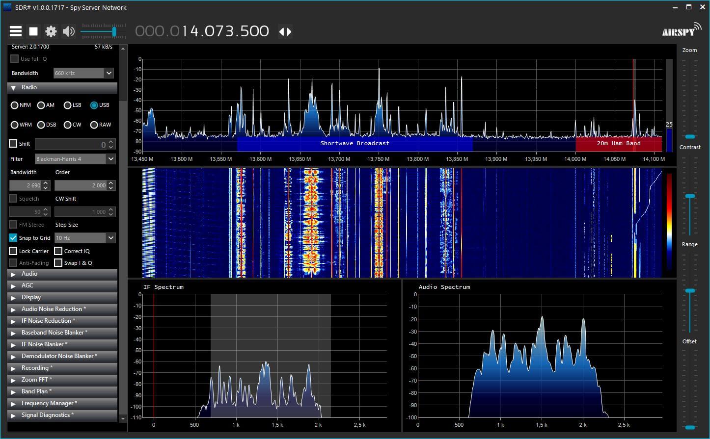
I took my trusty Loop On Ground antenna to the usual county park Forest Preserve which is relatively low in RF noise. I did some usual recording on 25 meters and poked around for something being captured by SDR Console. On 11910 kHz is NHK broadcasting daily from Koga, Japan. It is hearable at this location but is always an S7 or weaker signal despite its 300 KW of power no doubt due to being beamed away from the Midwest USA.
I recorded it using the SDR Console 10kHz bandwidth filter and created a separate noise recording from a nearby empty frequency. Here is the 2 minute portion of a Japanese music teacher. No noise reduction was applied:
I opened the noise and broadcast recordings in Audacity to see what I could do. Part 1 of my previously mentioned post details how I apply the Noise file. A big downside of using any kind of noise reduction software is that it is ridiculously easy to destroy the desirable characteristics of the original recording. Applying too much noise reduction, especially in the presence of constant, spiky lightning noises, will create both digital artifacts as well as very dull sounding results. So I used the Effect – Noise Reduction (NR) feature very carefully.
In this example, I used the Effect – Amplify feature on the one minute noise file. I applied just +1dB of Amplify to the whole file. Then I highlighted a 10 second section I thought was representative of the general background noise and chose Edit – Copy. Then, I opened the broadcast file, Pasted the 10 seconds of noise to the END of the file and highlighted just the 10 seconds of noise. Then I chose Effect – Noise Reduction – Get Noise Profile button. Amplifying the noise file by +1db does not sound like much but it seems to help according to my tests. Anymore than this and the Noise Profile would not recognize the noise without destroying the music.
I used the NR feature three times in succession using the following (NoiseReduction/Sensitivity/FrequencySmoothing) settings: Pass1 (3dB/0.79/1), Pass2 (2dB/1.28/1), Pass3 (1dB/2.05/0). Part of what I listened for was choosing the Residue circle and Preview button for any music or dialog that was being filtered out. If I heard something that came from the desired part of the recording in Residue, I knew that I hit the limit concerning the combination of Noise reduction and Sensitivity settings to engage. I used those Residue & Preview buttons over and over again with different settings to make sure I wasn’t getting rid of anything wanted. I also used the higher Noise reduction with lower Sensitivity to try to get rid of any momentary spiky type noise that is often associated with SWLing.
I messed around with a lot of test outputs of differing dB and Sensitivities and a lot seemed to depend on the strength of the broadcast signal compared to the noise. If the broadcast was weak, I could push the dB and Sensitivities a little harder. I also noted that with strong signal broadcasts, I could NOT use more than 1 dB of Noise reduction beyond a Sensitivity of about 0.85 without causing damage to the musical fidelity. This was a pretty low level of nuanced manipulation. Because of these minor level Audacity software settings, it dawned on me that it is very helpful to already be using a low-noise antenna design.
If the Sensitivity numbers look familiar, that is because I tried basing the series of Sensitivity on Fibonacci numbers 0.618 and 0.786. Don’t ask me why these type of numbers, they just ended up sounding better to me. I also needed a structured approach compared to just using random numbers! Probably any other similarly spaced Sensitivity numbers would work just fine, too.
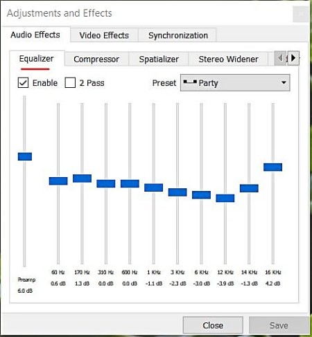
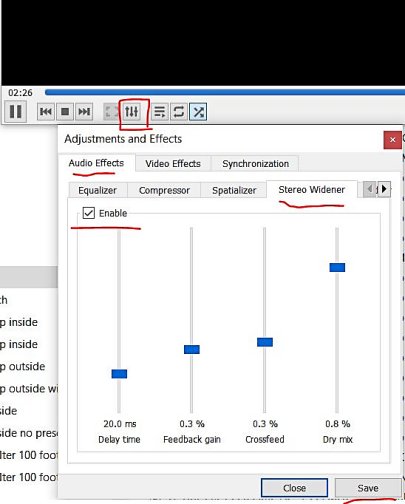
Now if you really want to go crazy with this, add Pseudo Stereo to your favorite version of this file (also detailed in Part 1) and playback the file using VLC Media Player. That software has a couple of interesting features such as an Equalizer and a Stereo Widener. You may or may not like using these features but sometimes it helps with intelligibility of the voice and/or music [VLC will also let you right-click a folder of music and choose to play all it finds there without having to import each MP3 file into a special “Library” of music tracks where they bombard you with advertisements].
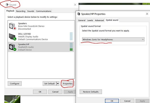
You can also turn on Windows Sonic for Headphones if you are using the Windows operating system. However, this can sometimes be too much audio manipulation for my tastes!
Here is the resulting NHK noise-reduced file with 9ms of delay with High & Low Filters:
Radio Thailand
Five days later I was out in the field again. This time I found Radio Thailand on 11920 kHz finishing up a Thai broadcast. It was a weaker S5 signal than the NHK example, so it would be a good test.
When I got home, I recorded the broadcast file at a Bandwidth filter of 8 kHz and using Slow AGC and the extra Noise file at 12kHz using Fast AGC. In a previous test I had noticed a very slight improvement in sound quality in the way noise seems to get out of the way quicker compared to Slow AGC (which is usually how I listen to shortwave broadcasters). I now try to remember to record the Noise file with Fast AGC.
Here is the original without any noise reduction:
This time the Noise file using Amplify +1dB did not help and I used it as-is for the 10 second Noise Profile. I then tried multiple passes of NR at higher and higher Sensitivities and ended up with these settings the best: Pass1 (1dB/0.79/0), Pass2 (1dB/1.27/0), Pass3 (1dB/2.05/0), Pass4 (1dB/3.33/0).
As a comparison, I tried recording only with SDR Console’s noise reduction NR1 set to 3dB and got this. I hear more noise and less of the music coming through:
Now for more crazy Pseudo Stereo to finish up the Audacity 4Pass version (nice Interval Signal of Buddhist bells ringing and station ID at the very end):
Summary
I do not understand why applying 3 or 4 separate 1dB Sensitivities of noise reduction is superior to just one Pass at 3dB Sensitivity (in Audacity) or the one 3dB noise reduction (in SDR Console). My guess is that doing 1 dB at different Sensitivities shaves off some spiky noise a little at a time, somehow allowing for more of the musical notes to poke through the noise cloud. Who knows but I can hear a difference in subtle musical notes and sharpness of voice and instruments. Probably the Fast AGC helps too.
Music is a Universal Language that we can share even when we don’t understand a word they are saying. And there is more music on the air than I thought. Some of these recordings sound surprisingly pleasing after noise reduction. The fake stereo is pumped through a CCrane FM Transmitter to a few radios in the home, or I can use the Beyerdynamic DT990 Pro headphones.
In addition to the loop inside the case with a 3-meter wire at one of the ends that join two telescoping style whips of one meter each short-circuited to take advantage of the entire length. At the other end of the loop, a cable that goes to the ground of the variable capacitor.
I can tune the whole range from 3 to 16 MHz with truly amazing results.
Thanks to you and all the friends of SWLing Post. Regards. 73. Giuseppe Morlè iz0gzw.
This is incredibly clever, Giuseppe! AS I mentioned before, I love how self-contained this makes the entire listening station and I especially love the built-in antenna options! This is truly a shack-in-a-case!
Many thanks to SWLing Post contributor, Jock Elliott, who shares the following guest post:
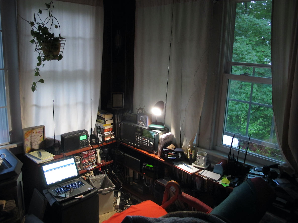
There’s a 50-foot antenna in this room. Can you spot it?
Got reception issues? An idea worth considering: the “Horizontal Room Loop.”
by Jock Elliott (KB2GOM)
When my radio room was in the front of the house (on the east side), it was easy to run a feedline to a large RF-hungry SWL dipole with various stubs and feeders.
Now, however, with my “shack” moved to the SW corner of the house, any attempt to mount an outdoor antenna of any significant length raised potential safety issues because of nearby electrical lines.
Monitoring VHF/UHF is no big deal because of high-performance scanner antennas. HF, however, presents challenges.
My main SWL receiver is a Satellit 800, which has the guts of a Drake R8 and also has a large telescoping vertical antenna. It works okay, but I wanted more signal. I had been looking at small loops and got some great recommendations on Radio Reference, but then I had a thought: what if I turned the 8′ x 12′ room into a giant horizontal passive loop?
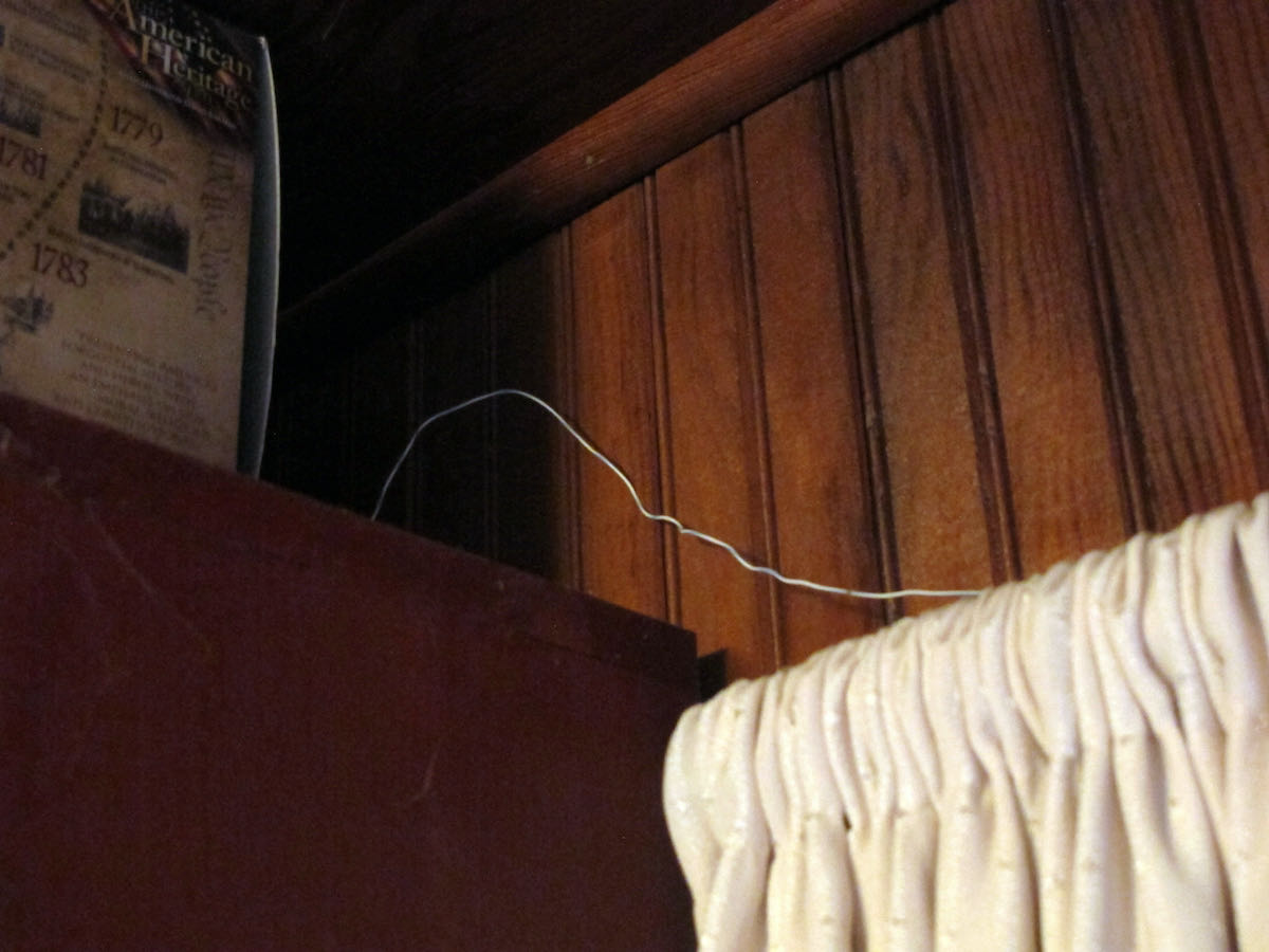
Here’s a hint.
So I called a ham friend and ran the idea by him. “Sure,” he said, “give it a try.” He gave me 25 feet of 4-conductor phone wire. Before I could use it, I had to strip off the outer insulation so I could get at the four separate insulated wires inside. The better half helped. Once I had the four wires, I connected two of them together and ran the resultant 50-foot strand around the perimeter of the room by taping the wire to the top of window frames and hiding the wire on the top shelves of book cases. As a result, the horizontal room loop is near the ceiling, about 7 feet in the air, and the room itself is on the first floor.
With the loop in place, I hooked the ends to the clip-in terminals on the back of the Satellit 800.
There’s a switch on the back of the 800 that allows me to quickly compare the loop with the radio’s built-in vertical antenna. And . . . it works! It pulls in more signal than the vertical (as measured on the signal strength meter), but I have not noticed a dramatic reduction in noise. On some stations, the horizontal room loop brings the signal up to full scale, and then the sound is very agreeable indeed.
In all, I am pleased with the results.
For anyone who wants squeeze more performance out of their shortwave receiver, I can recommend giving the horizontal room loop a try. It’s not expensive; it’s relatively easy to do (and undo if you don’t like the results), and just might improve your shortwave reception.
If you are not blessed with a bunch of window frames on which you could tape the wire for your room loop, you’ll have to get creative, but with lightweight wire, you don’t need a massive support structure. Tape, map tacks, or even self-adhesive Velcro segments might work for putting your room loop in place.
I don’t claim that this is the “ultimate” SWL DX antenna, but it certainly improved my situation. Perhaps others have suggestions for improving it.
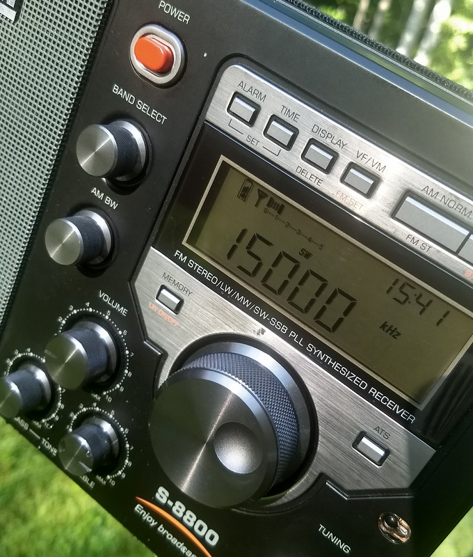
Many thanks to SWLing Post contributor, Giuseppe Morlè (IZ0GZW), who shares the following video and notes:
I recently bought a Tecsun S-8800 to be used mainly on shortwave. I carry it in an aluminum case to use it everywhere:
Many thanks for sharing this, Giuseppe! I love the integrated antenna–so clever!
Post readers: Giuseppe has had issues with the S-8800 accidently turning on in the case. Can anyone describe the button combo needed to lock the dial and controls during transport? I checked the manual but have found no reference. Please comment if you can help!