 Many thanks to SWLing Post contributor, Grayhat, who shares the following guest post:
Setting up a Mini Whip antenna
by Grayhat
I’ve been fiddling with my “balcony antenna” experiment for quite a while now, and I settled with a Linear Loaded Dipole (LLD, also known as “Cobra”) which, in my case, due to self-imposed limitations was a short one (about 9m total).
Since I mentioned it, here is a pic of the antenna showing its installation:

Click images to enlarge.
In the above image you can see the overall setup of the LLD, the modification I did, by adding additional wires to the end of the arms and also the Mini Whip location
The LLD served me well, from LW up to around 200MHz allowing me to listen to broadcasters, hams, aircraft communications, time signals and then more, and it’s definitely a keeper, but I wanted to give a try to the “Mini Whip” antenna, even if a lot of people discard it saying it’s a noisy antenna and not worth it; keep in mind the Utwente SDR uses it and it seems to work fine, so I had to give it a try !
Anyhow, after searching the internet for a suitable whip, I finally found this one:
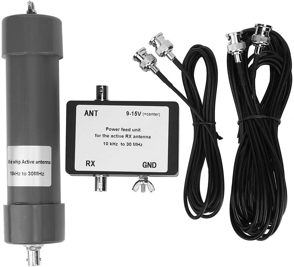
I bought the antenna on Amazon, but it’s also available on eBay and while the price isn’t the lowest one, I chose it since it uses BNC connectors only (some models use a mix of UHF/BNC or the like). This one had a top wing nut allowing to connect an additional (optional) external whip (may be useful on lower bands) and, last but not least, its color; being gray, it is quite stealth, which may be useful for some people (not my case, luckily). So I went on and ordered the antenna, the delivery took about 10 days and the package contents were exactly as shown above. The supplied coax is thin (RG-174 I believe) and it would be a good idea replacing it with some runs of RG-58, but for the sake of the experiment, I used the original wire.
So, having the antenna, I looked around for informations about the correct installation for the “Mini Whip” and found that in most cases, the reported poor performances of the Mini Whip are due to people installing it the wrong way. For reference and information about how the whip works and about how to properly install it, please refer to the information from PA3FWM found here and here.
Now, if you can place the whip in a garden or yard, using a pole, the correct installation of the whip is the one shown in this pic:
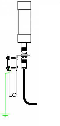
If you carefully look at the image you will notice that the whip sits above the supporting (metallic) pole and that the ground of the connector is electrically connected to the pole (through the clamp). Plus, the pole is then grounded (at the bottom) and the coax (which has chokes) runs away from the metallic pole.
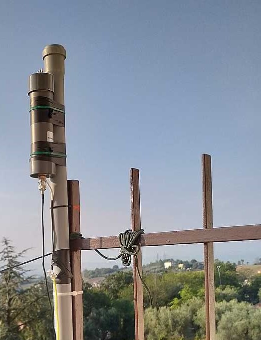
What does the above mean ? Well, the Mini Whip antenna needs a “counterpoise” (ground) to work, and installing it as above, instead of using the coax braid as its counterpoise, the Mini Whip will use the supporting pole, this helps a lot minimizing the noise and it’s one of the tricks for a proper setup, the other one is placing the whip as far away from the “noise cloud” of your home as possible. In my case, I choose the far end of the balcony–also since I had a nice support there, the image below shows the whip installation using a piece of PVC pipe I bought at a nearby home improvement store:

At first, I just installed the antenna without the ground wire and with the coax coming down vertically from the connector. When I compared the whip to my LLD, the results were discouraging: the noise floor was much higher and a lot of signals, which the LLD received without problems, totally disappeared inside the noise floor.
Being the kind of hard-headed guy I am (and having read the documentation about proper setup) I went on and made further modifications.
Let me detail the installation a bit better with this first image (click to enlarge):
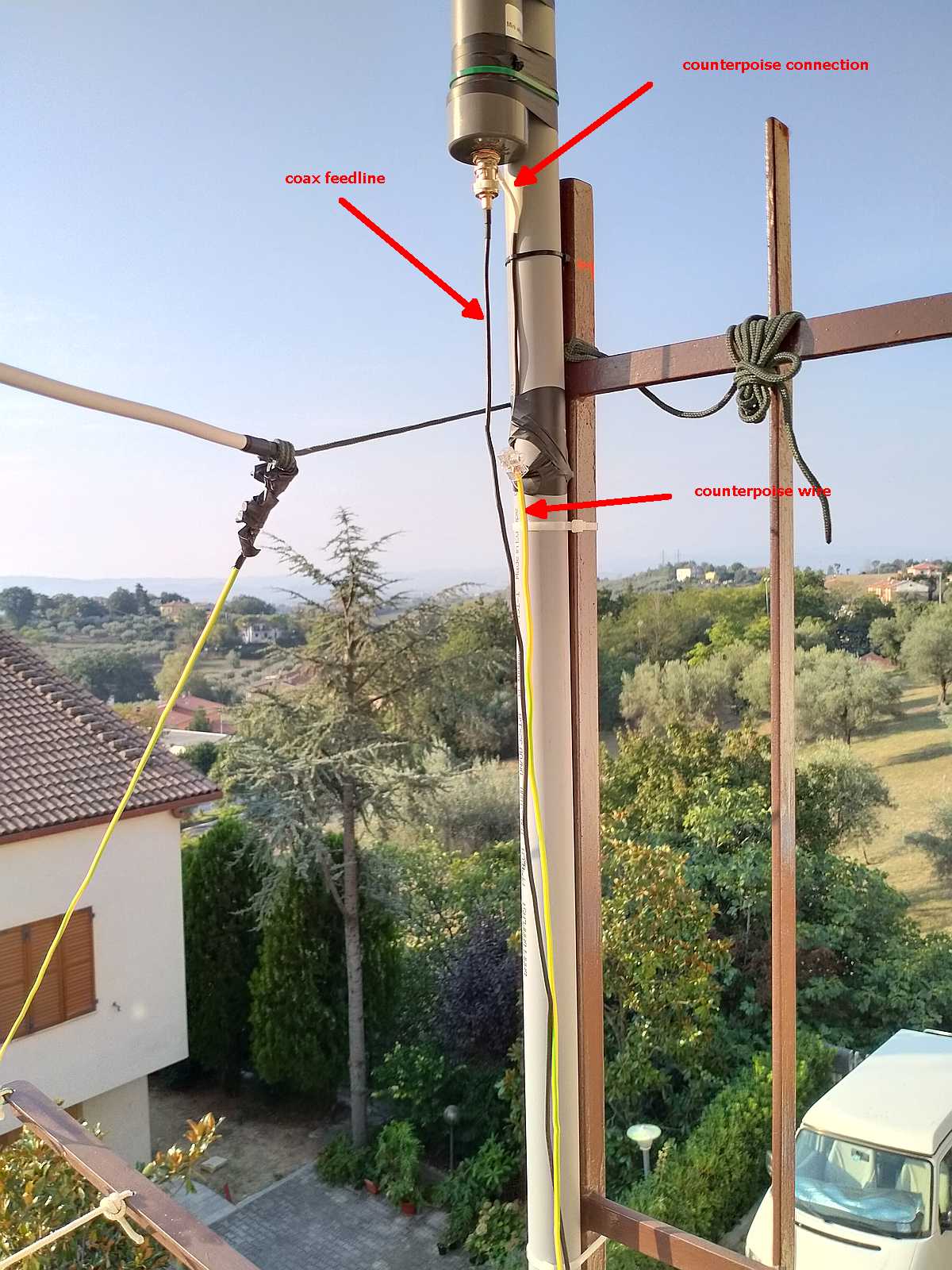
As you can see in the above image, the whip is supported by a piece of PVC pipe which keeps it above the metal fencing of the balcony (or a support pole if you’ll use it) and I also connected a short run of insulated wire to the ground of BNC plug at the bottom of the whip. This short run goes to a wire clamp which allows it to connect to the “counterpoise” (ground) wire.
In my case, since the balcony was at 2nd floor, I didn’t have a way to give to the antenna a real ground, so I decided to run a length of wire (AWG #11) down the pipe and then along my balcony fencing (10m total). An alternative, which will also work for roof installations, would be using chicken wire (fencing). In such a case, you may lay as much chicken wire as you can on the floor/roof and connect the wire coming down from the whip ground to it. I haven’t that that (yet!) but I think it may further lower the noise and improve performances.
Notice that in the case of the Utwente Mini Whip, the antenna support pole is connected to metallic roofing so it has plenty of (virtual) ground.
Later on, I improved the setup by raising the antenna a bit more and routing the wire (almost) horizontally from the feedpoint to reduce coupling with the vertical “counterpoise” wire.
The image below shows the final setup:
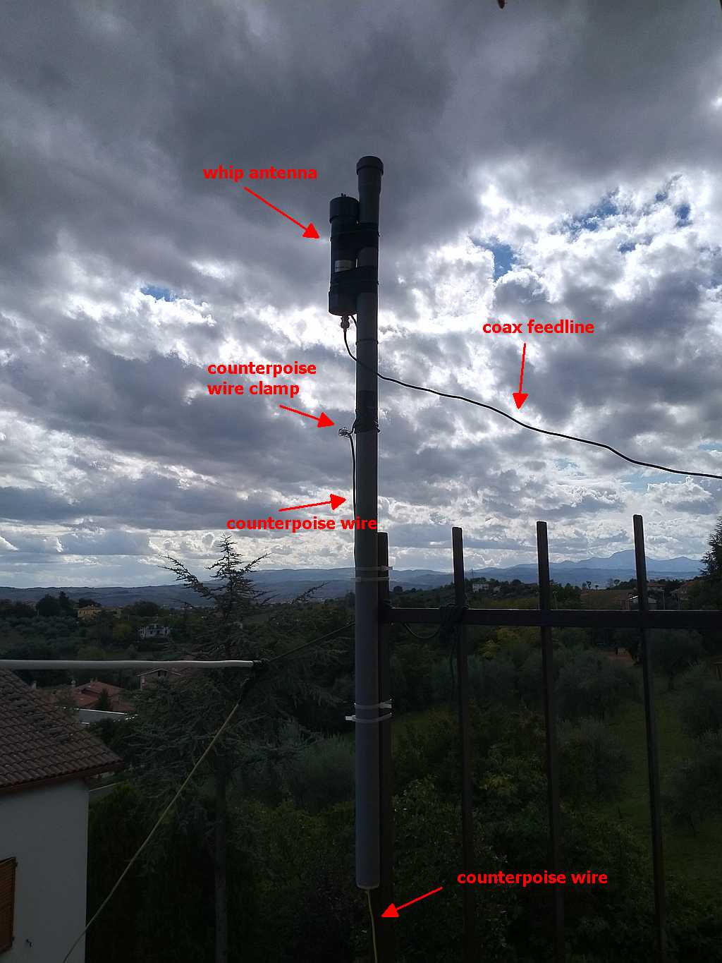
While not visible in the above image, I also wrapped the coax wire in a loop at the point where it’s held by the fencing and added some snap-on chokes to the coax at the point where it enters the building.
With all the modifications in place, the antenna started performing as it was designed to. The noise floor is still a bit higher than the one of the LLD, but given that it’s an active antenna, that’s to be expected
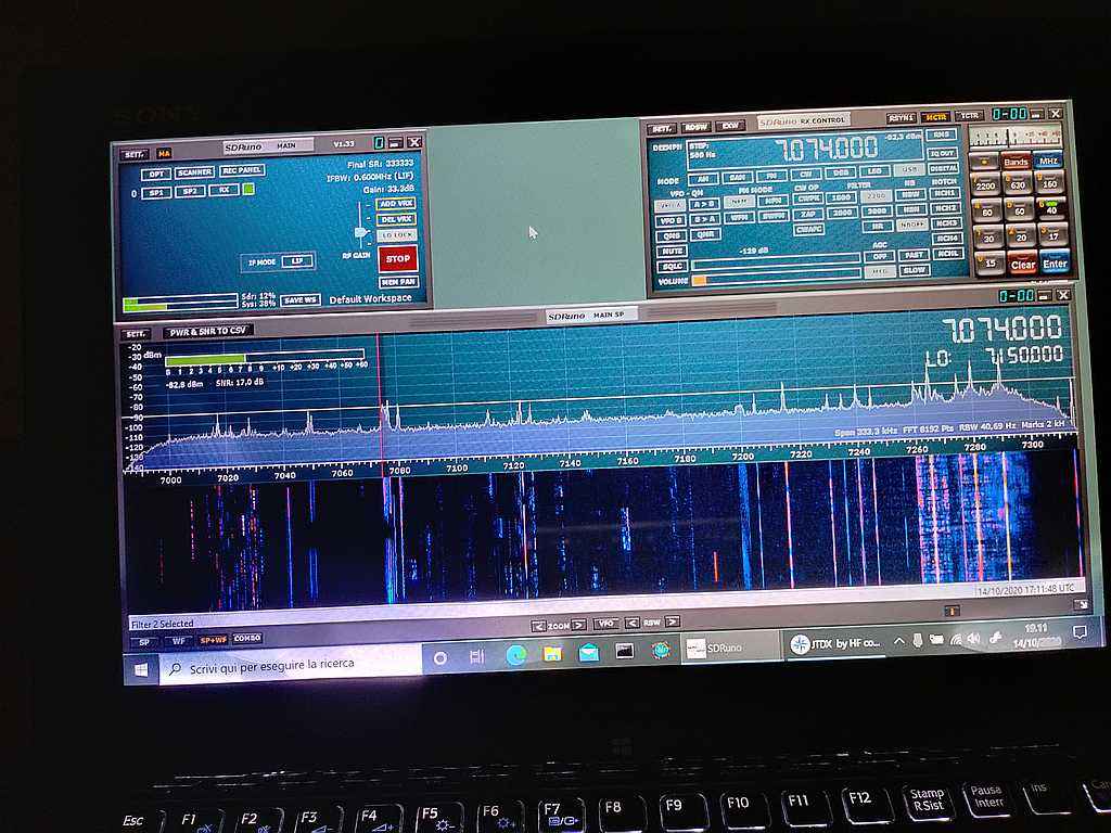
To give you an idea of the signals and noise floor, here are a couple of images taken from the screen of my laptop while running SDRuno. The first one shows the waterfall for the 40m band
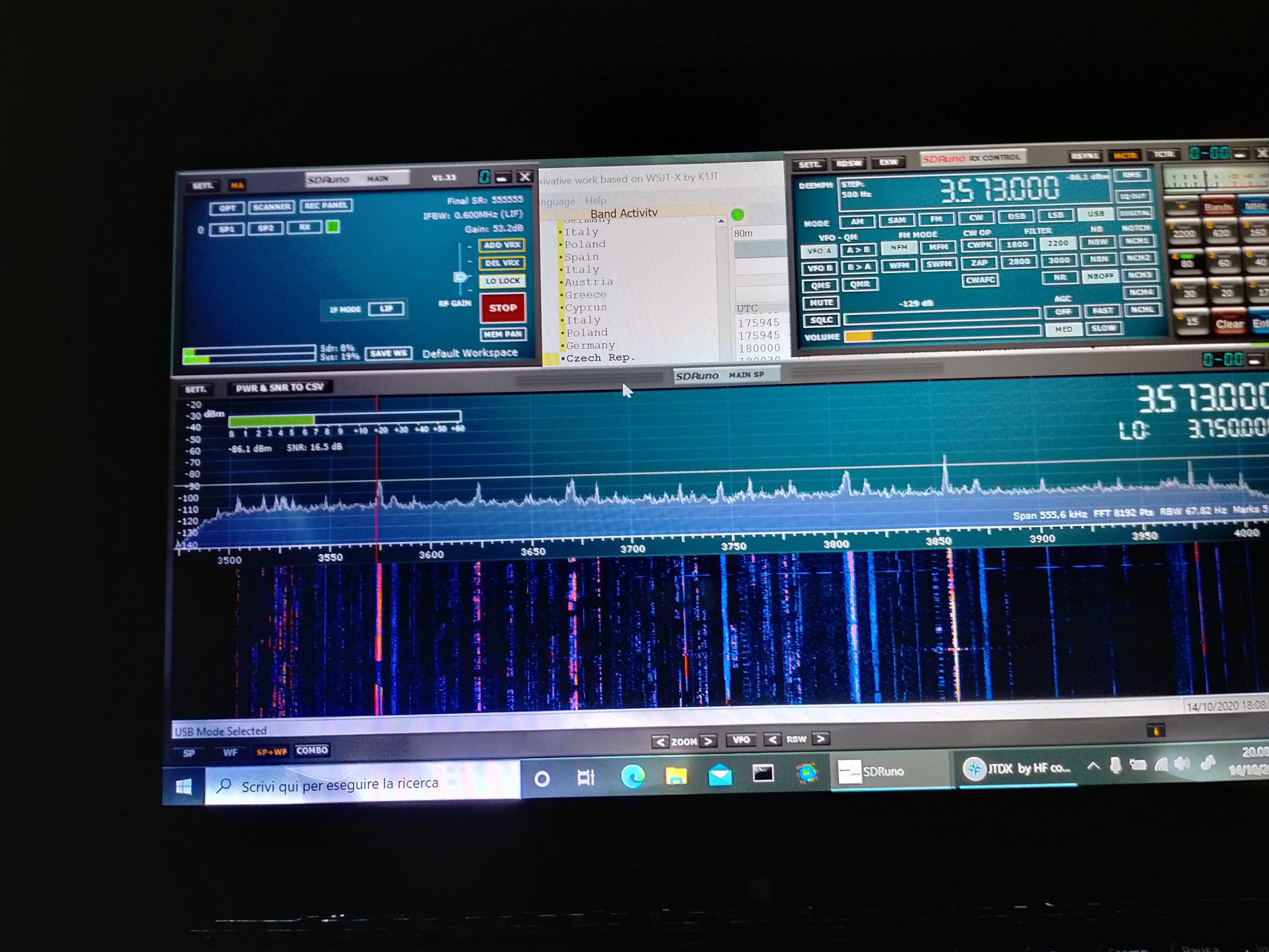
While the second one, below, shows the one for the 80m band:
At any rate, my usual way of testing antenna performance (and modifications effects), aside from some band scanning/listening, is to run an FT8 session for some hours (and optionally repeat it over some days) and then check the received spots.
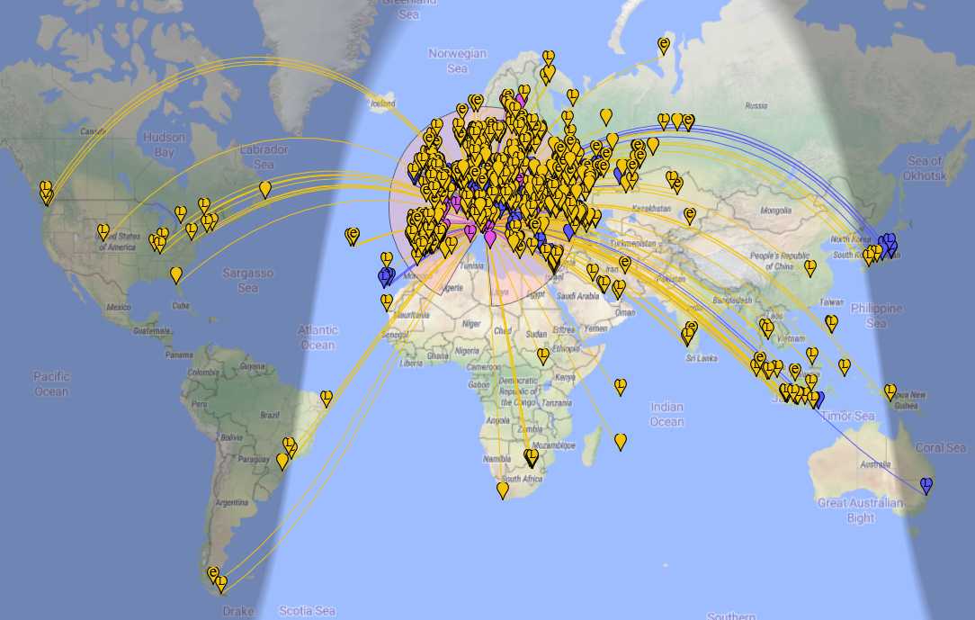
In the case of the Mini Whip, after all the modification to the setup, I ran an FT8 session using JTDX for some hours and the images below show the received spots. The first image shows the whole map of the received stations:
While the second one below is a zoom into the European region to show the various spots picked up there; the different colors indicate the 20m (yellow), 40m (blue/violet) and 80m (violet) bands:
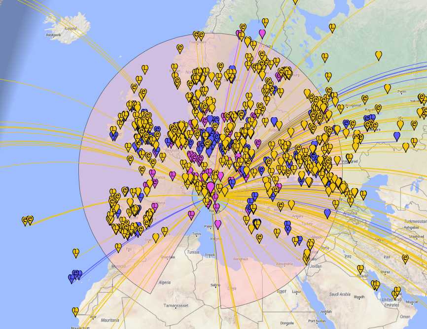
As you can see, the Mini Whip performed quite well despite the “not exactly good” propagation.
While some time ago I’d have discarded the Mini Whip as a “noise magnet”, as of today, with a proper installation, I think it’s a keeper. While it can’t be compared to bigger antennas, I believe it may be a viable antenna for space-constrained situations. The only thing it needs is a bit of care when setting it up to allow it to work as it has been designed to.
Brilliant job, Grayhat! Thank you so much for sharing your experience setting up the Mini Whip antenna. As you stated, so many SWLs dismiss the Mini Whip as “noisy”–but with a proper ground, it seems to perform rather well. The benchmark example of a Mini Whip’s performance must be the U Twente Web SDR.
Thank you again, Grayhat!

 Many thanks to SWLing Post contributor, Jaap de Goede, who shares the following note: