 The following article originally appeared in the November 2018 issue of The Spectrum Monitor magazine:
Shortwave Portables: Some of my favorites
Being a radio writer and blogger, I’m often asked, “Isn’t radio dying?” or “How long are you going to keep listening to radio when there are so many other options out there?”
My answer? It’s simple:
Radio is about the journey. And radios are the vehicles with which I explore our planet, albeit sonically. I’ll stop listening to radio when it stops transporting me to far-flung, fascinating places across our planet.
I’ll stop listening to radio when when it can no longer provide the kind of direct information and understated entertainment that is, for me (and a few others like me), a welcome relief from the overwhelming demands and distractions of the Internet.
And I’m perhaps a bit anachronistic in that I prefer radio’s subtler theatre of the mind over the mindless image consumption that television demands; thus, I’ll stop listening to radio when it too, tells me what I must think, what I must imagine, and what I must feel.
In short, radio is my tool for exploration, and I continue to enjoy tuning, listening, logging and learning from it. Very fortunately, I have the great pleasure of being in the middle of the world of radio technology in my reviews, evaluations, and alpha/beta testing.
This is why, over the years, I’ve made an effort to share some of my picks of the litter with others. So when TSM editor Ken Rietz asked if I would be interested in writing a feature about this, how could I resist?
What follows is a series of mini-reviews which focus primarily on the portable radio market. This is, by definition, a curated list, but I’ve done my best to include a variety of receivers I regularly recommend. The radios are listed roughly from least expensive ($25) to most expensive ($270), and I’ve only included models that are in production at the time of this publication.
Ever-popular portables
Portables are truly the most popular category of radio among shortwave radio enthusiasts, and it’s no wonder why! Among their other virtues, modern portables can pack a lot of performance into an affordable package, they’re great for travelling, and their all-in-one nature makes shortwave listening accessible to virtually everyone.
 Since I’m in the constant stream of correspondence and comments from radio enthusiasts, I know another reason some listeners consider portables simply invaluable: portables give us refuge from noise. Since many of us live in, and/or travel to, busy urban areas filled with radio interference, portables give us a means to head to the park, beach, or the countryside to escape the noise and increase our odds of working DX.
Fortunately for us, modern portables pack features of which, in former radio-listening days, we could have only dreamed.
What follows is a list of my favorite portables, listed by price in US dollars, with the least expensive first. Please note that retailer links include Amazon and eBay affiliate links that support the SWLing Post with your purchase.
Best Portable Shortwave Radios
$25 – $50 Range
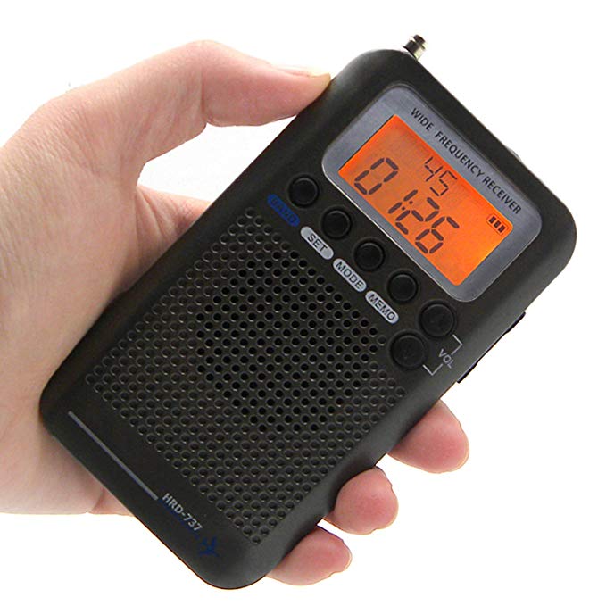
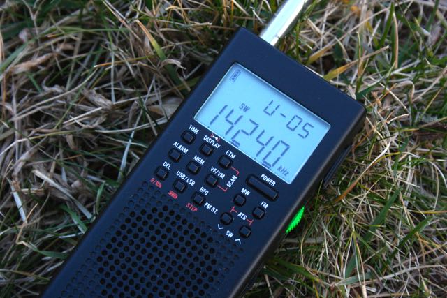
Tivdio V-115 / Retekess V115 / Audiomax SRW-710S
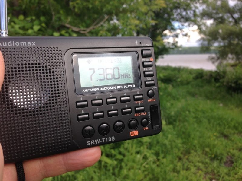
Listening to the BBC Midwinter Broadcast on June 21, 2017 in Québec.
Pros: Affordability, sensitivity, built-in recording and audio playback features, compact size, impressive audio from internal speaker
Cons: Mutes between frequencies, front panel buttons feel rather cheap, no SSB mode, sluggish response from controls, small telescoping whip
Summary: For about $25, it’s hard to complain about the V-115. Its performance and list of features exceeds expectations for radios in this price range, which are generally a disappointment. As for myself, I mainly use the V-115 as receiver to make off-air recordings and as an occasional backup radio. Unless your budget is very tight, don’t buy the V-115 as your main receiver; rather, buy it to keep in the glove compartment of your car or in your go-bag. Note that this radio carries a number of brand names and has been rebadged many times. Click here to read more reviews of the V-115 on the SWLing Post.
Retailers:
Grundig Mini
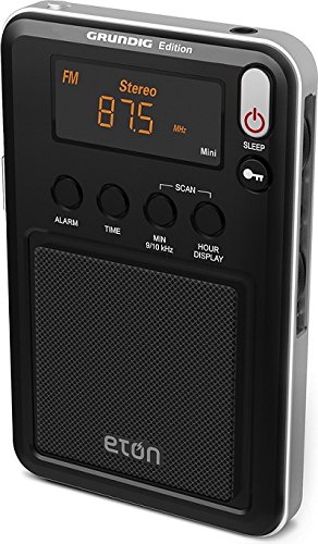
Pros: Compact, simple, adequate sensitivity and selectivity, clear backlight display, surprisingly decent audio from internal speaker
Cons: No direct frequency entry, no SSB mode, limited features compared with pricier receivers
Summary: The Grundig/Eton Mini is the latest in the lineage of the Mini series from Eton. The Mini has remained a popular radio because it delivers decent performance, with above average audio and makes for a nice broadcast listening companion. I recommend the Mini as a gift for those who want a simple pocket radio to operate with an easy-to-read display––great for the traveler or for elderly parents or grandparents who don’t like too many fussy buttons. Certainly a great value for the money.
Retailers:
Tecsun PL-380
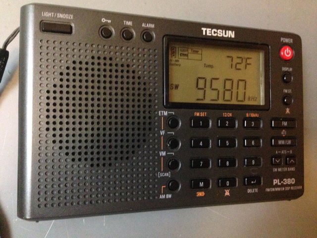
Pros: Excellent sensitivity and selectivity, excellent audio via headphones, multiple AM bandwidths, ETM auto-tuning, excellent ergonomics, responsive controls, direct frequency entry, excellent bang-for-buck
Cons: No SSB mode, slight muting between frequency changes
Summary: The venerable PL-380 was my first ultralight Tecsun radio. It’s been on the market for many years, no doubt due to its solid performance. The PL-380 has an excellent receiver with impressive sensitivity and selectivity. The ETM auto-tuning feature is ideal for those of us who like to travel. The PL-380 is durable, affordable, and in terms of performance, is very similar to the PL-310ET (below). The PL-310ET might have a slight edge in terms of sensitivity. But for just $45, you simply can’t go wrong with the PL-380.
Retailers:
Tecsun PL-310ET
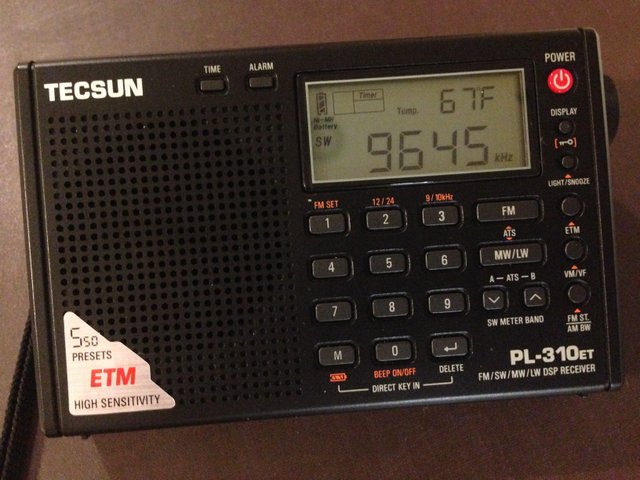
Pros: Excellent sensitivity and selectivity (perhaps slightly more sensitive than similarly-priced PL-380), excellent audio via headphones, multiple AM bandwidths, ETM auto-tuning, excellent ergonomics, responsive controls, direct frequency entry, excellent bang-for-buck
Cons: No SSB mode, slight muting between frequency changes
Summary: The PL-310ET, like its cousin the PL-380, is a classic ultralight radio and performs brilliantly for the price. The PL-310ET has long been the backup radio I’ve taken along on mini DXpeditions and field-listening sessions. The ETM auto-tuning feature is ideal for those of us who like to travel. The PL-310ET is reliable, and you’re hard-pressed to find a better performer under $50––indeed, it rivals some receivers twice its price. A solid choice for the budget-minded radio enthusiast and Ultralight DXer.
Retailers:
$50 – $100 Range
XHDATA D-808
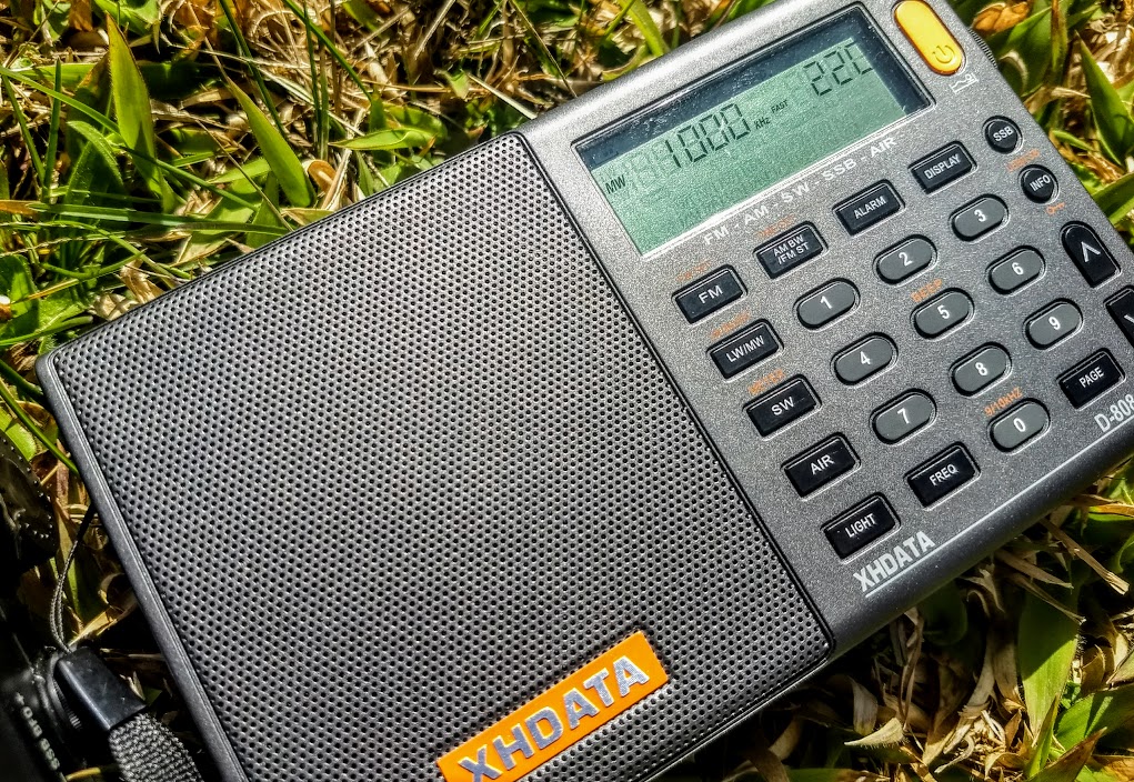
Pros: Impressive overall performance, SSB mode, multiple AM and SSB filter widths, above-average audio from internal speaker, RDS, dedicated fine-tuning control, decent battery life from four standard AA cells, includes AIR band
Cons: Mutes between frequency changes, sluggish response from controls
Summary: The XHDATA D-808 was, no doubt, the most surprising receiver to hit the market in 2017. It’s an impressively sensitive radio across the bands, and can be snagged for an affordable price (generally $75-80 US). I was very skeptical of the D-808, but when I put it on the air, I discovered it gave some of my full-featured portables a run for their money. It is, indeed, a budget workhorse. If you live in New Zealand or Australia, you might find the very similar Digitech AR-1780 a more accessible option. Internally, the D-808 and Digitech AR-1780 (see below) are very similar. Click here to read more D-808 reviews on the SWLing Post.
Retailers:
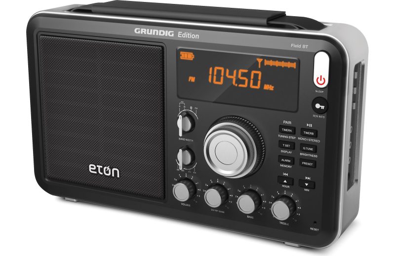
Eton Field BT

The Grundig Field BT
Pros: Impressive sensitivity, excellent audio fidelity, can be used as a Bluetooth speaker, intuitive display, dedicated RF gain, simple tactile controls, overall quality feel
Cons: Clunky/quirky tuning is painfully slow, no direct frequency keying, no SSB mode
Summary: Last year, my friend Troy Riedel and I met at Mount Mitchell State Park to compare the Eton Field BT with the benchmark ($270) Tecsun S-8800. We were impressed that the Field BT did an admirable job competing with the S-8800 (see below). Indeed, due to the Field BT’s excellent audio, some broadcasts were slightly more intelligible than on the S-8800 (noting the S-8800 also has excellent audio). The only negative that was quite obvious at the time was how cumbersome it was to tune the Field BT compared with the S-8800. One year ago, the Field BT was widely available for $129––lately I’ve seen the price as low as $80 shipped. If you’re looking for a lunchbox radio that packs serious performance, room-filling robust audio, and you don’t mind slow tuning, the Eton Field BT is an excellent choice.
Retailers:
CountyComm GP5-SSB (a.k.a. Tecsun PL-365)
Pros: Excellent sensitivity, audio fidelity quite good via headphones, effective SSB mode, multiple AM and SSB bandwidths, very good medium-wave reception with supplied external bar antenna, unique form factor for one-handed operation, uses three standard AA batteries
Cons: No direct frequency entry, audio tinny via internal speaker, AGC doesn’t cope with fading as well as other comparable portables, no back stand nor rotatable whip antenna; thus this radio is not ideal for tabletop listening, supplied belt clip feels flimsy––if you plan to use this in the field, consider purchasing the excellent CountyComm GP5 series rugged case.
Summary: The GP5-SSB was one of the first sub-$100 DSP portables with SSB mode. Since its release others have entered the market (see XHDATA D-808 above for example). The GP5-SSB has a unique form factor tailored for handheld operation, much like a handie talkie. I keep a GP5-SSB in my backpack to use while on hikes, and am always very pleased with its performance. If you’re looking for a bedside or tabletop portable, I would recommend other similarly-priced receivers like the XHDATA D-808 or Digitech AR-1780. Note that if you live outside North America, you might find it easier to purchase the Tecsun PL-365 which is identical to the GP5-SSB. Click here to read our full review of the CountyComm GP5-SSB.
Retailers:
C. Crane CC Skywave
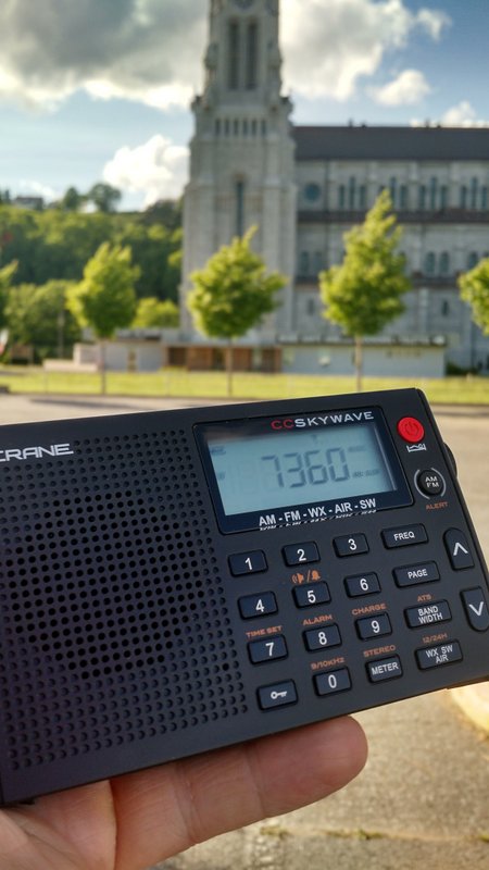
Listening to the 2016 BBC Midwinter Broadcast to Antarctica while traveling in Canada with the CC Skywave.
Pros: Overall great sensitivity and selectivity for a portable in this price class, considerate design, well-tailored for the traveler, AIR band is truly functional, NOAA Weather radio reception excellent, includes soft silicone earphones (in-ear type) actually worthy of AM/SW listening, auto scanning with the up/down buttons is very rapid, uses common micro USB port for power/charging
Cons: No SSB mode, internal speaker audio is somewhat tinny (use of the voice audio filter helps), no external antenna jack, mutes between frequency changes
Summary: I think the original CC Skywave is a brilliant little radio. Although it lacks SSB mode, it’s a fine broadcast receiver and one of the most sensitive travel portables on the market. For those of us living and traveling in North America, the CC Skywave is a veritable “Swiss Army Knife” receiver, as it not only covers AM, FM and shortwave, but is a capable AIR band and incredibly adept NOAA/Environment Canada weather radio receiver. At $90, I believe it’s the best radio value in the C. Crane product line. If the lack of SSB mode is a deal-breaker for you, consider the Skywave’s pricier brother, the CC Skywave SSB (below), also an excellent performer. Click here to read our full review of the CC Skywave.
Retailers:
$100 – 200 Range
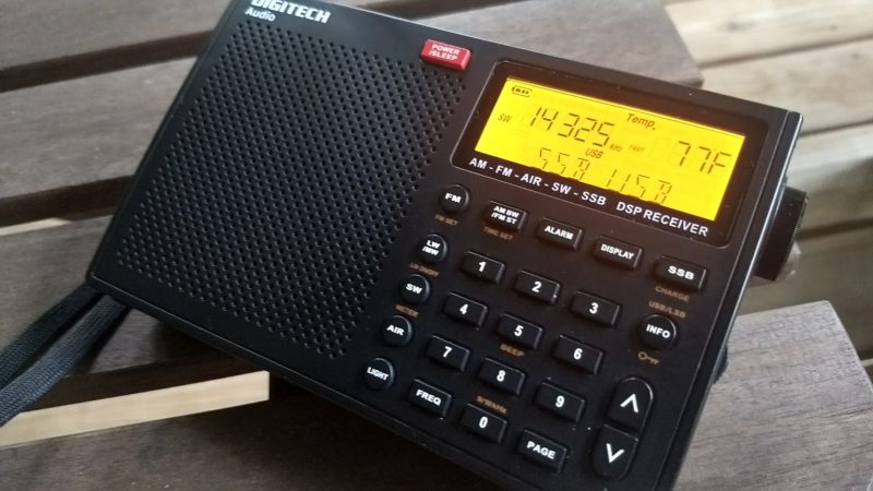
Digitech AR-1780

Pros: Impressive overall performance, SSB mode, multiple AM and SSB filter widths, above-average audio from internal speaker, RDS, dedicated fine-tuning control, decent on-air battery life from four standard AA cells, includes AIR band
Cons: Mutes between frequency changes, sluggish response from controls. Note that at least one user has reported quick battery discharge when the radio is turned off. This has not been the case with my unit–in fact, it’s often turned off for a couple months at a time and maintains a steady, healthy charge.
Summary: Digitech is not a brand known for delivering enthusiast-grade receivers to the Australian/New Zealand markets through retailer Jaycar.. While they’ve a number of portables on the market, so many are plagued with internal noise and quirky controls. The AR-1780 is an exception. For $129.00 AUD (roughly $103 USD), you’re getting a full-featured radio that is, by and large, a pleasure to operate. The AR-1780 has its quirks, but so do so many ultra-compact portables in this price bracket. As mentioned in the cons above, there have been reports of some units draining batteries rather quickly when turned off (essentially in standby)––I have not experienced this, but this issue has been reported by a number of AR-1780 owners. The AR-1780 is certainly worth considering if you live in Australia or New Zealand. Note that the Digitech AR1780 and previously mentioned XHDATA D-808 share a nearly identical receiver design although their outer dimensions are slightly different. Click here to read our full review of the Digitech AR-1780.
Retailers:
Tecsun PL-660
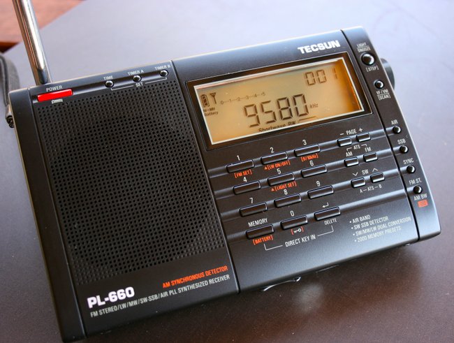
Pros: Smooth digital tuning with no muting between frequencies, excellent synchronous detector, functional SSB mode, direct frequency entry via keypad, brilliant ergonomics, excellent sensitivity and selectivity (a best-in-class!), excellent price point and value for benchmark portable performance
Cons: BFO knob instead instead of push-button SSB, only two filters (wide/narrow), lacks a line-out jack
Summary: I’ve owned a PL-660 since 2011 and still take it on DXpeditions and to use as a benchmark when evaluating new receivers. It has rock-solid performance all around with pleasant audio from the built-in speaker, and one of the best synchronous detectors on the portables market. The PL-660 is the radio I’ve recommended more than any other for newcomers to the hobby: it’s a very capable DX machine with an ergonomic, intuitive interface. Click here to read other SWLing Post reviews that include the PL-660.
Retailers:
Tecsun PL-680

The Tecsun PL-680
Pros: Excellent sensitivity and selectivity on the shortwave bands, improved weak signal stability over the PL-660, stable sync lock, proven form factor with good overall ergonomics, great internal speaker––an improvement over the PL-660, but not as good as the PL-880––in short, other than medium-wave performance (see con), a worthy replacement for the PL-660; also sports excellent audio from the PL-680 internal speaker: improved over the PL-660, but not matching the fidelity of the PL-880
Cons: Medium-wave performance is lackluster, marginal noise floor increase on the shortwave bands (compared with the PL-660), lacks a line-out jack, SSB frequency display on my unit is + 1 kHz, so slight BFO adjustment is needed
Summary: If you’re a shortwave radio listener, you’ll be pleased with the Tecsun PL-680. In all of my comparison tests between the Tecsun PL-660 and Tecsun PL-680, the PL-680 tends to edge out the PL-660 performance-wise. This coincides with blind user surveys I conducted on the SWLing Post. If you’re a medium-wave DXer, you might skip over the PL-680; the PL-660 is likely a better choice for you. If you’re a casual medium-wave listener on the other hand, you’ll probably be pleased with the PL-680. Click here to read our full review of the PL-680.
Retailers:
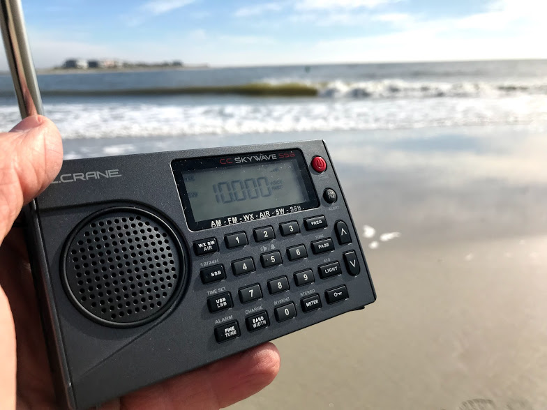
CC Skywave SSB
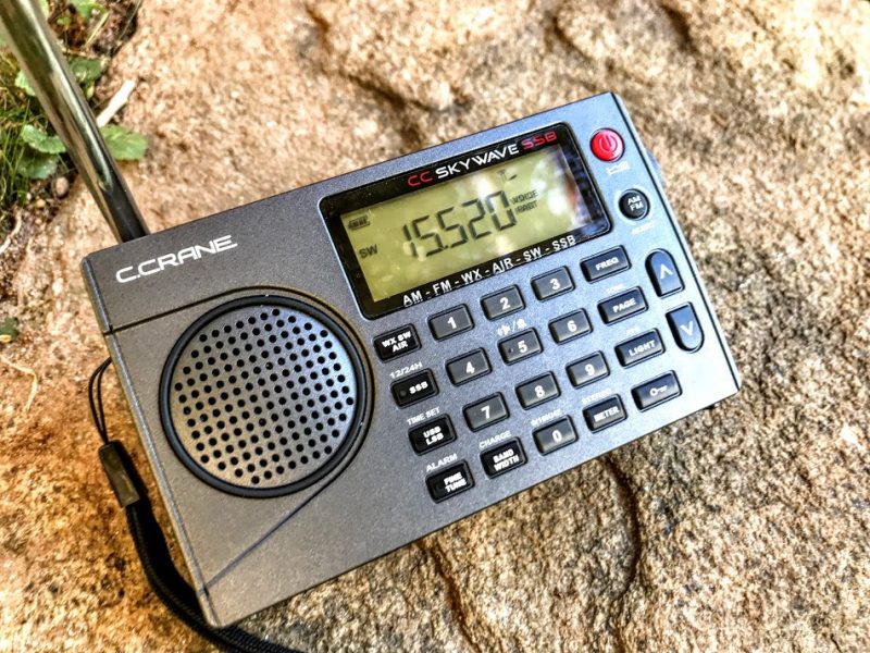
Pros: Considerate design and ergonomics, well-tailored for the traveler, excellent sensitivity and selectivity for a compact radio, faster AIR scanning compared with the original CC Skywave, better HF frequency coverage than the original Skywave (1.711-29.999 MHz, compared to 2.300-26.100 MHz), pleasant SSB audio, multiple bandwidths in both AM and SSB modes, no overloading noted, well-written operation manual, excellent weather band reception, nice red LED indication lamps for SSB and Fine Tune engagement, NOAA Weather radio reception excellent, includes soft silicone earphones (in-ear type) actually worthy of AM/SW listening, uses common micro USB port for power/charging, excellent battery life from two AA cells
Cons: At $169, US the CC Skywave SSB is certainly the priciest compact portable on the market, yet mutes between frequencies, engaging SSB mode requires 2-3 seconds of delay (common for this DSP chip), no RDS, no audio-out jack, no sync detector (a “con” in this price class), no long-wave reception, first production run had some quirks which have now been addressed by C. Crane (in case you shop for a used unit).
Summary: I love the CC Skywave SSB. Sure, I wish it had RDS, an audio-out jack, didn’t mute between frequencies, and was less expensive (the current price of $169 seems excessive). But overall, it’s a fantastic package. I’m impressed with the amount of performance the Skywave SSB provides with such a short telescoping antenna. Since first being introduced to the Skywave SSB last year, it has become my choice travel portable. Check out our initial review of the CC Skywave SSB and the important updated second production run review.
Retailers:
Tecsun PL-880
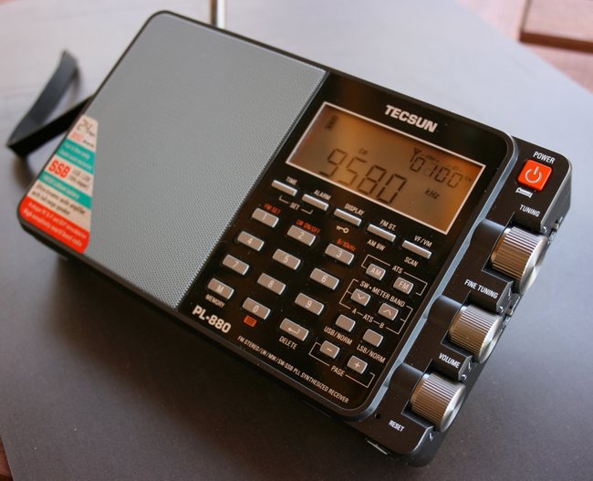
Pros: Excellent ergonomics, excellent sensitivity and selectivity, superb audio from internal speaker, wide array of filter options in both AM/SSB more than on any sub-$200 portable on the market!), absolutely no muting between frequencies even while using a .5 kHz filter in SSB, sturdy carrying case has dedicated pocket for English operation manual, single supplied rechargeable battery delivers a very long life
Cons: Two-second delay when changing modes (AM/SSB/AM sync), some audio splatter on peaks in weak signal DX, sync detector (hidden feature) delivers mediocre performance and substantially reduced audio fidelity, AM (medium wave) prone to imaging if strong AM broadcasters are nearby, supplied rechargeable battery is not as common as AA batteries
Summary: I’ve owned the Tecsun PL-880 for five years and it continues to impress. Tecsun has made iterative changes to the firmware over time, and now this radio is one of the best performers in the sub-$200 price bracket. The audio from the PL-880 internal speaker is simply unsurpassed in this size of radio. The PL-880 isn’t perfect, but it does an amazing job, pleasing DXers from every angle and even ham radio operators who appreciate the narrow filter settings in SSB mode. All in all, you can’t go wrong with the PL-880––it’s certainly a quality piece of radio kit! Click here to read our full review of the PL-880. Click here to read our list of PL-880 hidden features.
Retailers:
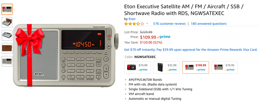
Eton (Grundig Edition) Executive Satellit
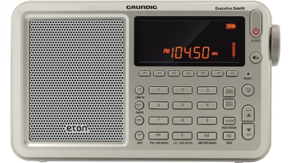
Pros: Excellent sensitivity, excellent audio from built-in speaker, ergonomic and intuitive interface, uses common AA batteries, multi-joint swivel antenna is best in class, excellent build quality, display is easy to read, effective station memory management
Cons: Mutes between frequencies, executive Satellit model typically costs more than previous non-executive model
Summary: The Satellit has a dedicated following among hard-core DXers, both the audio and superb sensitivity placing it well within the realm of benchmark receivers. It’s a fantastic field radio and feels like one that should serve you over the long haul. It’s not a perfect radio; I especially wish it didn’t mute between frequency changes, although Eton seem to have minimized this in the latest production runs. If you’re seeking a super-sensitive portable to sniff out weak DX, then the Satellit is worth serious consideration. Check out some of Oxford Shortwave’s previous posts which include the Executive Satellit.
Retailers:
$200+ Range
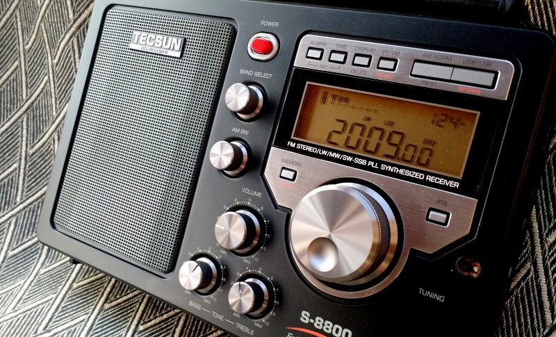
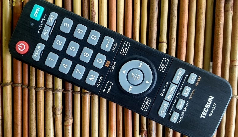
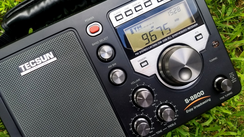
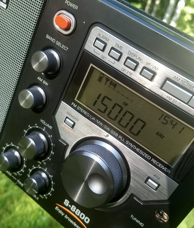
Tecsun S-8800
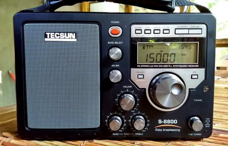
Pros: Brilliant audio fidelity from built-in speaker, dedicated AM bandwidth and fine tuning controls, excellent bespoke IR remote control, capable SSB mode, excellent shortwave sensitivity, excellent shortwave selectivity, excellent FM performance, easy-to-read backlit LCD digital display, remote control beautifully equipped for full radio functionality, included 18650 rechargeable lithium batteries power this radio for hours, BNC connection for external antennas, does not overload even when connected to large external antennas
Cons: Lackluster mediumwave performance, no synchronous detector, no direct keypad entry (pro: remote control, however, has excellent keypad entry), can’t charge and listen at the same time as is not designed for AC operation, no backstand, when in narrowest SSB filters AGC can’t reliably handle audio/signal changes, slight “warbling” sound while using fine-tuning control in SSB mode, no RDS display on the FM band
Summary: If your primary use of the S-8800 is for medium-wave or long-wave DXing, you should look elsewhere. While the S-8800 will serve you well with local AM stations, it will not dig signals out of the noise like other better-equipped AM receivers. But: if you’re primarily a shortwave radio listener, you’ll certainly be pleased with the S-8800! The S-8800 consistently outperforms my beloved Sony ICF-SW7600GR and my Tecsun PL-880. Indeed, it is the most sensitive and selective shortwave portable I own. On the flip side, it’s also the most expensive: $268 at time of publication. If you want top-class HF performance from a portable radio and you expect superb audio, I think you’ll find the S-8800 well worth your investment. Click the following links to read our full review of the S-8800, 13dka’s review which compares the S-8800 with the PL-660 and D-808 and Dan Robinson’s most recent S-8800 comparative review.
Retailers:
There’s a portable for everyone
You might have noticed that there’s a portable receiver on this list for everyone:
- The listener who wants turn-on-and-play functionality
- The casual listener
- The hiker
- The traveler
- The DXer
- The ham radio operator
Keep in mind that this is a curated list of some of my favorites that are widely available on the market new. There are a number of receivers on the market––the Degen DE1103 comes to mind––which would have made it to this list had they not been “updated” with a DSP chip. Manufacturers add DSP to reliable models in order to increase profit margin, since DSP chips cost a fraction of traditional receiver design. DSP chips have revolutionized the portable market in many positive ways, but if they’re not properly implemented in a set, they can produce higher noise floors, audio anomalies, shaky AGC, and other undesirable traits. The DSP receivers in the list above have properly implemented DSP technology and, save the cheapest models, are all what I would consider “enthusiast grade” radios.
What about other types of radios?
Of course, if you’ve become addicted to radio, you shouldn’t stop at portables! I would encourage you to check out the three-part Software Defined Radio Primer published in September (Part 1), October (Part 2), and November (Part 3). The SDRs I mention in the primer are essentially what I consider the best of the best.
Of course, there are still a handful of tabletop shortwave receivers like the Alinco DX-R8T HF receiver, the Elad FDM-DUOr SDR receiver, and the Icom IC-R8600 wideband receiver. All are top-notch performers and, when paired with an effective antenna, can pull out weak signals much better than a portable radio ever could.
If you’re a ham radio operator, take advantage of modern general-coverage transceivers. Only a couple decades ago, most transceivers were “ham band only” and the ones that were not compromised performance if they included the broadcast bands. This is no longer the case. Modern general coverage HF transceivers can rival dedicated tabletop receivers in many cases. I’m particularly fond of the Icom IC-7300, IC-7200, and Kenwood TS-590SG as home stations, and the Yaesu FT-818, Elecraft KX3, and the Elecraft KX2. This is a mere sampling of some of the excellent general-coverage transceivers on the market. Before you purchase a general-coverage transceiver, simply make sure it has AM mode and that the bandwidth is wide enough for pleasant audio. Ask current owners how their transceiver sounds on the broadcast bands.
In summary
As you select your next radio, take into consideration how and where you plan to use it, as well as what you’re willing to spend. The good news is, we live in an era with an extraordinary number of options covering all price ranges and uses. So, be assured: there’s a radio out there just waiting to sonically transport you to far-flung and fascinating regions, too.
Vive la radio! Long live radio!
Do you enjoy the SWLing Post?
Please consider supporting us via Patreon or our Coffee Fund!
Your support makes articles like this one possible. Thank you!