Category Archives: Shortwave Radio

Expectations after dusting off a radio that’s been in storage

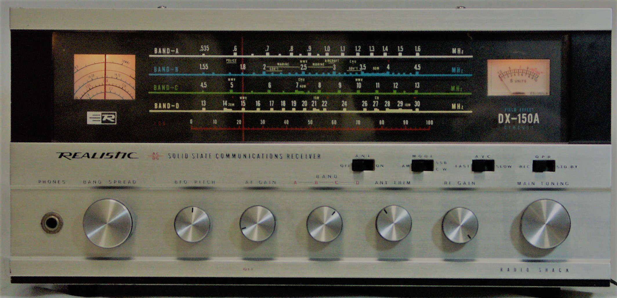
Realistic DX-150A (Source: Universal Radio)

Many thanks to SWLing Post reader, Alfred, who writes:

I purchased a Realistic DX150 radio when it was first introduced. I used it for many years and then stored it away for some time. A few years ago I decided to use it again. After the bandspread control was repaired at a local radio shop, I used it for a short time and then stored it away.

Yesterday, I took it off the shelf to see what was on the air waves. I did not have much success in getting any broadcasts to tune in strongly/clearly. I am writing to ask what my expectations should be – given the low performance of the radio and the state of shortwave transmissions these days. The mechanical aspect of the bandspread control needs attention again. My question is: Should I be able to pick up transmissions at some good level/ quality?

Thank you for your advice and recommendations.

Alfred, thank you for your inquiry and I hope you don’t mind that I’m sharing it here publicly because I’ve been receiving so many similar questions in the past few months.

I assume with so many people sheltering at home because of Covid-19 and, suddenly, having time available to catch up on projects and pastimes, they’re pulling solid-state receivers off of the shelf and putting them on the air again!

You asked: “Should I be able to pick up transmissions at some good level/ quality?”

A simple question, with a potentially complicated answer!

A simple answer first…

If your DX-150 is still electrically and mechanically functioning as it should, and you have it connected to an effective antenna, then yes, you should be able to receive transmissions!

Caveats…

As I’ve told numerous others who have resurrected solid-state gear from storage, there’s a good chance gear that’s a few decades old could have dead or leaky capacitors. Sometimes the symptom of this is a “hum” in the receiver’s audio, but bad capacitors (or “caps” as we like to call them) can also cause less obvious issues with the radio’s overall performance. If you’ve tried everything and suspect your radio needs repair, there are some great repair technicians out there. My friend Vlado is one of them, but I think he may have paused repairs during the Covid-19 pandemic.

Radios that have sat on a shelf or in a basement for years may also have built up oxidization on switch and knob contacts. Carefully applying a product like Deoxit on contacts can make a world of difference and bring your radio back to life.

In addition, if you haven’t hooked up your radio in a couple of decades, you may be surprised by the amount of radio interference and noise (RFI) our home electronics generate. A random wire or indoor antenna that worked well in the 1970s might not work at all if you have high levels of RFI where you live. RFI has the same effect on your radio as a noisy restaurant environment has on your ability to hear a friend who is speaking at a normal volume level across the table from you. RFI can deafen your receiver. There are antennas that can help mitigate RFI, and there are also techniques you can use to help mitigate it.

Depending on where you live in the world, you will find the shortwave landscape isn’t the same as it was, say, in the Cold War years. Fear not! There are still numerous broadcasters out there, so people who say shortwave is “dead” simply aren’t listening.  Check out ShortwaveSchedules.com and Prime Time Shortwave for what’s out there and where to find broadcasters on the bands. If you like music, I highly recommend Alan Roe’s guide to music on shortwave.

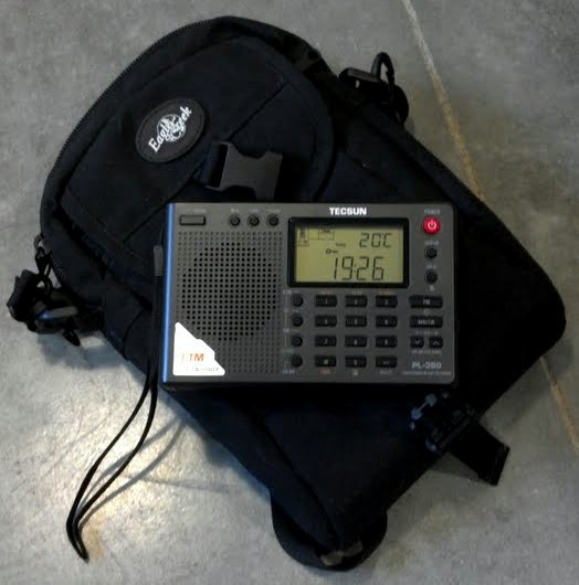
The Tecsun PL-380 is one of several compact portables that can be purchased for $50 or less.

If you find that you’re not hearing anything on your DX-150 (or other vintage radio)–even after following some of the advice above, yet you still want to explore the shortwaves–you might consider investing in a modern portable radio. Not only do modern portables sport a digital frequency display (which helps locate stations), but they allow you to take your listening to the field. You will be surprised what you can receive when you walk or drive to an area far away from man-made electronic noises. Tabletop radios like the DX-150 are not terribly portable. If you’re looking for some portable shortwave radio suggestions, check out this post. (Incidentally, if you found this post because you’re mainly seeking an AM/FM radio for local news and info, check out this post.)

Getting back on the air…

Alfred (and others who have recently contacted me) I hope this post gives you some helpful guidance. In truth, there are still many other issues that could affect your ability to get the most out of your vintage solid-state receiver. Let’s assume, though, that the solution is simple! Give it a go, and take your time tuning across the bands on different days and with your receiver in different locations.

My hope is that SWLing Post readers will also comment on this post with other suggestions to help you back into the world of SWLing!


Do you enjoy the SWLing Post?

Please consider supporting us via Patreon or our Coffee Fund!

Your support makes articles like this one possible. Thank you!

Free Radio Skybird: “One alternative to lockdown lunacy”

(Source: Pete Madtone)

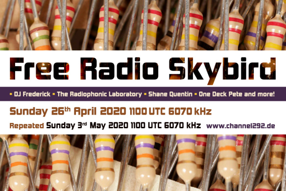
This Sunday coming 26th April 2020, DJ Frederick’s Free Radio Skybird will be broadcasting another show in its weekly spring run at 1100 UTC (1200 UK) on 6070 kHz via Channel 292. 

This week’s episode features Justin Patrick Moore’s Radiophonic Laboratory and One Deck Pete’s “Radio connects us all” mix featuring Patrick McGoohan, Sasskia, Mokka and Camille Murray. We’ve also the debut of Shane Quentin from the excellent Garden of Earthly Delights radio show who’s bringing us a bit of “Radio Re-flex-ology”.

Tune in using your shortwave radio in the 49 Metre band on 6070 kHz or by using the link here. It’s going to be one interesting hour!

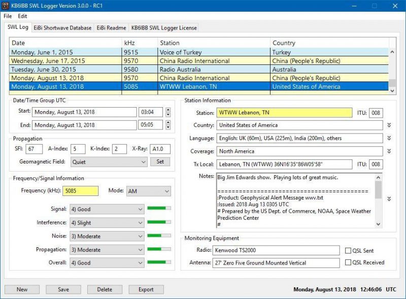
New KB6IBB SWL Logger version for MacOS

Many thanks to SWLing Post contributor, Valery Titievsky, who writes:

Good news from Jeff, KB6IBB.

I’ve waited a long time for this news and it has finally happened!

Jeff has published a new release of his “KB6IBB SWL Logger” now for Mac OS.

It is available as a free download here: https://sourceforge.net/projects/kb6ibbswllogger/

Excellent news!  Thank you for sharing this tip, Val!

Bruce’s passion for SWLing and single transistor regenerative receivers

Many thanks to SWLing Post contributor, Bruce (VE3EAR), who shares the following:

I live in the village of Saltford, ON, Canada, near the eastern shore of Lake Huron. It’s a quiet location signal wise, and I’m lucky that I have enough property to erect some big antennas. My two favourites are a 1200 foot long terminated Beverage, aimed at 50 degrees true, which targets Europe and the UK. The other is a 333 foot perimeter delta-loop, apex up and oriented north-south. Both antennas are fed with RG-6 coaxial cables and impedence-matching transformers.

I use the loop with a recently acquired Airspy HF+ Discovery SDR and the Gqrx SDR software, in my iMac. I like to listen to amateur activity on 160, 80, and 40 metres, along with the few shortwave broadcast station that are still on the air. I also like to listen to the trans-Atlantic air traffic control stations in Shannon, Ireland and Gander, Canada.

I once heard a U2 spy plane returning from a mission over Russia!

My other hobby is designing and building simple, one transistor regen receivers, most of which tune the AM broadcast band, although I have built a couple covering the lower portion of the HF broadcast bands as well, just for a challenge. All my receivers are built breadboard style.

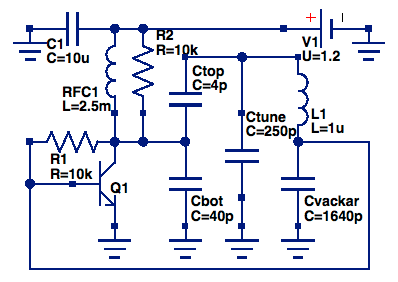
My favourite of them is one based upon the Vackar oscillator, with the addition of a diode detector and “Benny”, as is used in crystal radios.

Here is the schematic of the Vackar circuit:

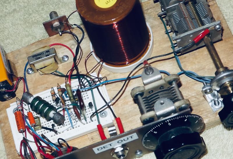
The diode and “Benny” connect to the collector of the transistor, then to a pair of home made headphones using two telephone earpiece elements installed in a pair of hearing protectors. The receiver is both very selective and very sensitive. Here is a pic:

Most of the electronics are on a proto-board, which allowed easy component substitutions during the build. When I had it optimized, I decided to leave it that way! The controls, left to right, are on-off switch, regen, fine tuning, main tuning, and range selector switch, hidden behind the reduction drive. Audio is taken from the DET OUT jack, to either the headphones described above, or to an audio amplifier for listening with a speaker.

Bruce, it sounds like you certainly have an excellent spot and excellent antennas for DXing! I love regen receivers as well and radio design can hardly be more simple.

Thank you for sharing!

Radio Waves: Burning 5G, WAUK Simulcasts C-19 Radio, Remote US Ham Exams, and Guardian’s Top 10 Radio Stations

Photo by Joshua Anderson Slate

Radio Waves:  Stories Making Waves in the World of Radio

Because I keep my ear to the waves, as well as receive many tips from others who do the same, I find myself privy to radio-related stories that might interest SWLing Post readers.  To that end: Welcome to the SWLing Post’s Radio Waves, a collection of links to interesting stories making waves in the world of radio. Enjoy!

Many thanks to SWLing Post contributors Tom Daly and the Southgate ARC for the following tips:


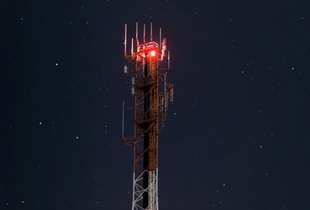
5G Conspiracy Theories Trigger Attacks On Cellphone Towers (NPR)

Dozens of cellphone towers and equipment boxes have been set aflame in Britain, apparently by people who believe 5G technology is helping to spread the coronavirus.

Milwaukee AM Station Temporarily Simulcasting SiriusXM Channel (North Pine)

Good Karma Brands has temporarily set aside the ESPN Radio lineup on WAUK/540 (Jackson-Milwaukee) and is simulcasting a COVID-19 information from a satellite radio channel.

The temporary programming is coming from SiriusXM’s Doctor Radio and coronavirus information channels. The simulcast on WAUK began Monday, April 20. It wasn’t announced how long it will continue.

WAUK operates in tandem with “ESPN Milwaukee” FM signal WKTI/94.5 (Milwaukee), with the AM station normally continuing to carry ESPN from 7 a.m. to 3 p.m. while the FM side is in local programming.

Locally, Good Karma also owns News/Talk outlet WTMJ/620 (Milwaukee).[…]

USA: Fully-Remote Amateur Radio License Exam Administration (Southgate ARC)

The USA’s Ham Study group have released the latest update on the Fully-Remote Amateur Radio Exam Process

On March 26th, 2020, the first-ever fully-remote amateur radio exam was held to demonstrate the capabilities of these technologies and align with the needs of the W5YI VEC that authorized the trial.

Several other VE Teams have begun administering fully-remote exams using ExamTools.org along with video conferencing systems.

Read the Press Release at
https://blog.hamstudy.org/2020/04/fully-remote-amateur-radio-license-exam-administration/ […]

10 of the best music radio stations around the world (The Guardian)

Thousands of radio DJs are employed around the globe to play Anglophone pop and rock. If there’s such a thing as “world music” to them, it’s REM and Queen.

But there are many more radio stations around the world that play music from their own cultures, past and present, mainstream and marginal. When it comes to virtual travel, music is arguably the easiest and most enjoyable way to transport your brain out of Covidland to places you’ve visited – or plan to – in person.

The net is pretty chaotic, with dozens of aggregators and formats. But here are 10 soundscapes to explore. Turn up the volume to Mexican cantina level.[…]


Do you enjoy the SWLing Post?

Please consider supporting us via Patreon or our Coffee Fund!

Your support makes articles like this one possible. Thank you!

More about hacking VGA cables to make binocular ferrite cores

A few days ago, we posted an a short article showing how Oscar hacked a VGA cable to make a binocular ferrite core for his homebrew NCPL/Youloop antenna. Many thanks to SWLing Post contributor, Grayhat, who explored this clever hack a little further:

Hi Thomas, Having some time in my hands Sunday afternoon I decided to try pulling out the ferrite chokes from a VGA cable I had around, and while doing so, I decided to coarsely document the process with some pics.

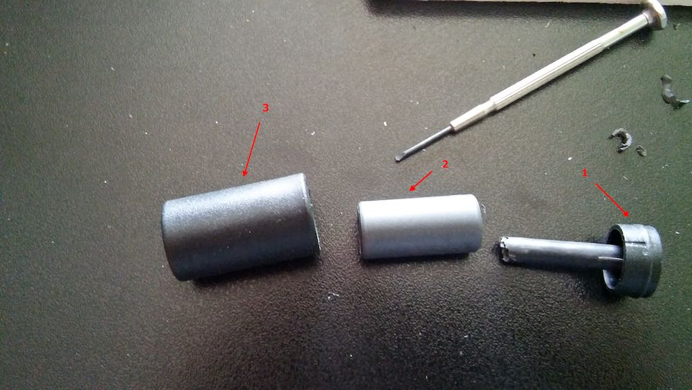
Figure 1

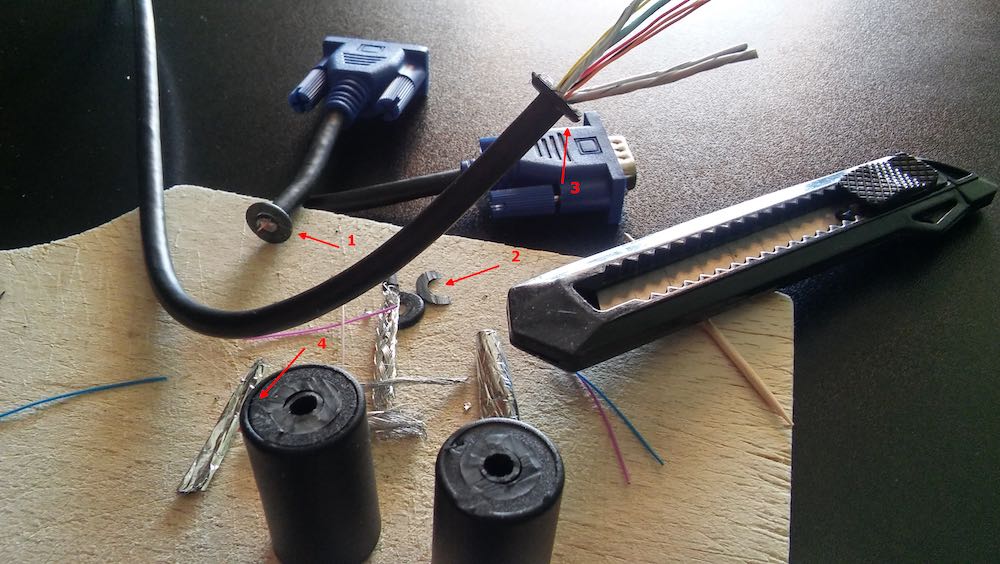
The first thing to do is use a cutter to carefully cut around the “washer” shaped plastic at the connector end of the choke (fig.1, #1,#2, #3 above), then on the same side, after cutting the plastic also cut the inner conductors (fig.1, #1).

Move to the other side of the choke, gently cut around the “washer” w/o cutting the inner conductors, now pull the cable to extract it from the choke (fig.1, #3), repeat the process for the other choke.

Now look at the “cans” containing the chokes, one side of those will show a “cap” (fig.1, #4), insert a small screwdriver into the center hole and gently ply to one side to raise the cap and extract it (fig.2, #1).

Figure 2

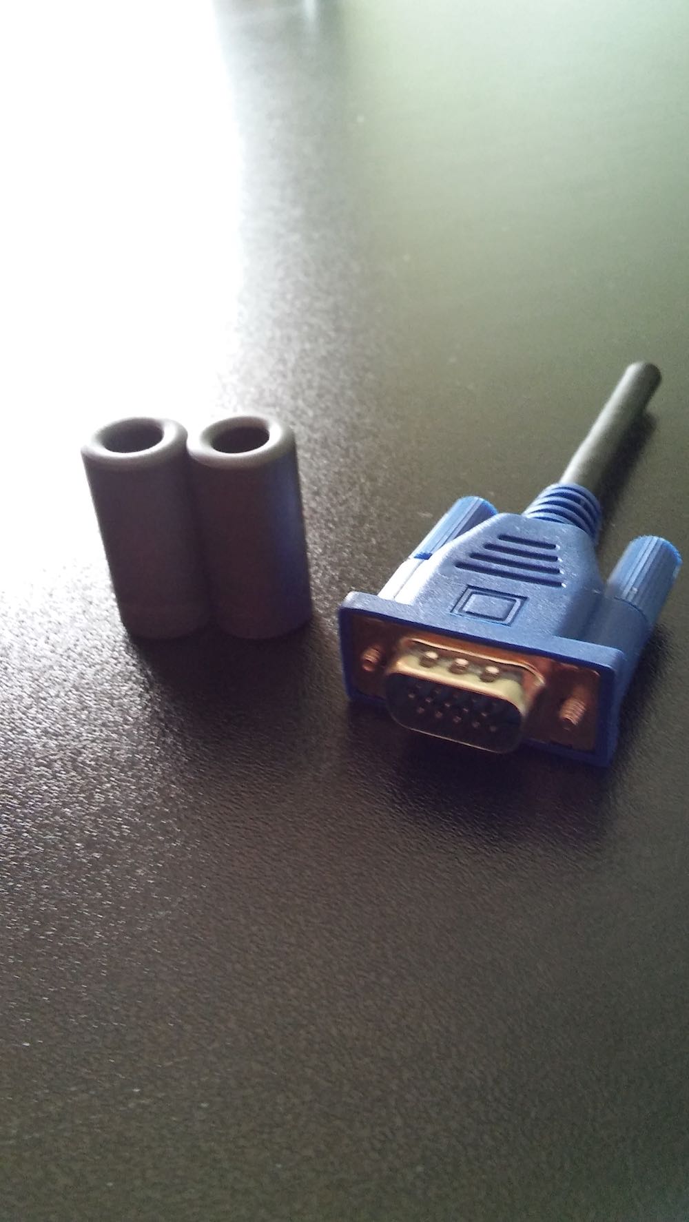
The result will be as in fig.2, where #1 is the closing cap, #2 is the ferrite choke and #3 is the “can” containing the choke. Repeat the process and you’ll have two ferrite chokes as shown in fig.3 (the VGA connector is there to give an idea of the dimensions):

Figure 3

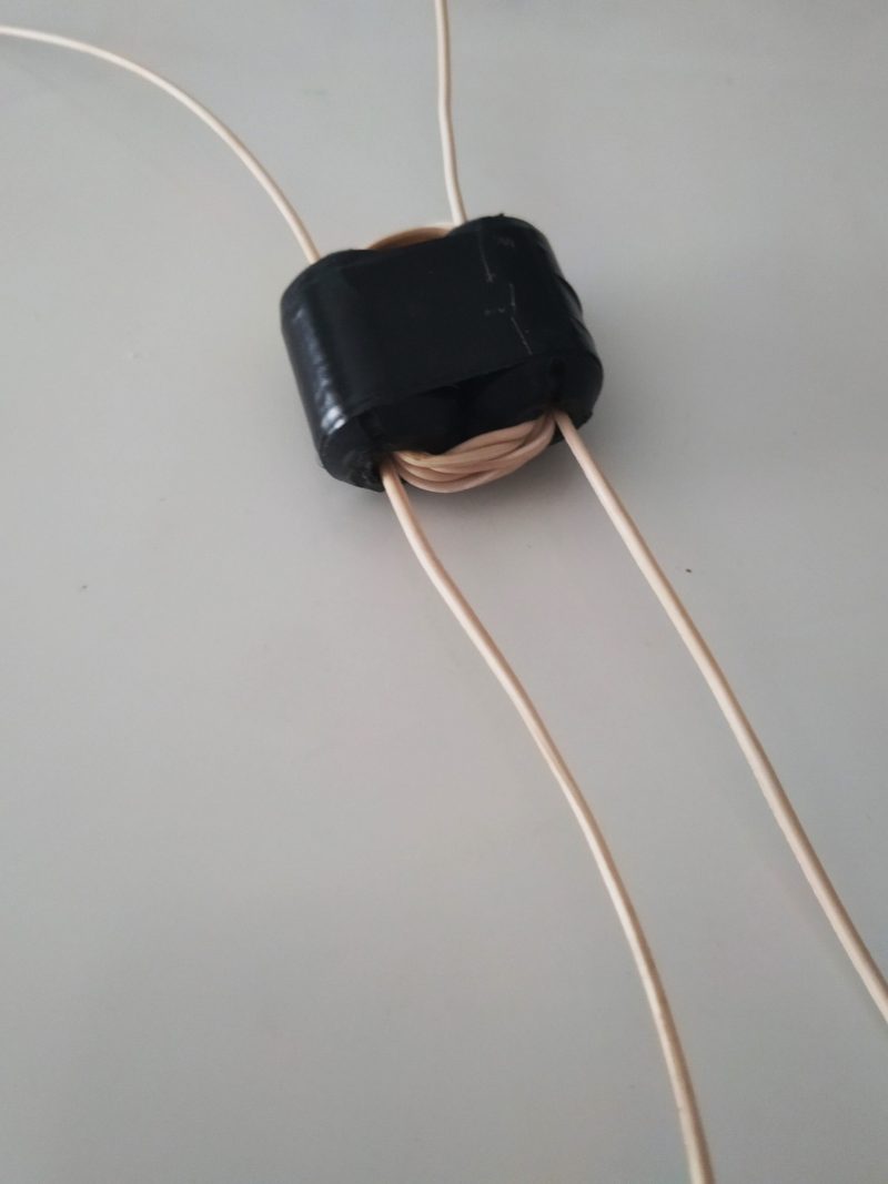
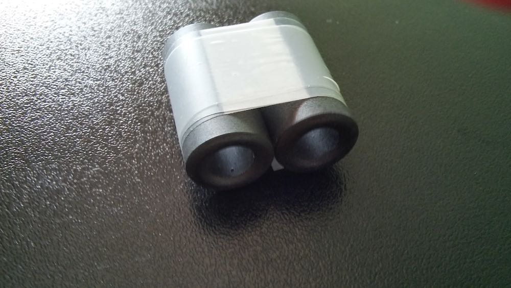
At this point, use some tape (duct tape will be a better idea, I used clear tape just to make an example) to tie the two ferrites together as in fig.4 and you’ll have your “binocular ferrite”:

Figure 4

Willing to use whatever you have there to wind the transformer, you may now extract the tiny insulated wires from the VGA cable (fig.1, #3, see wires) and use them for the windings.

Notice that other cables may use different choke “cans” which may need to cut a larger portion around the flat faces at the ends. But remember that in any case, those are just “snap-in” cans containing the ferrites, so with a bit of attention and patience, it shouldn’t be difficult extracting the ferrites.

Based on a little online research, it sounds like the ferrites used to choke the VGA cables (HDMI ones too) are generally type #31.

Looking at some #31 datasheets it appears that while #73 is works fine at frequencies below 50MHz, the #31 is best suited for the 1-300MHz range.

This means that #31 won’t be the best pick for mediumwave, although if one doesn’t have another choice… well, go for that! Also notice that the ferrite permeability is different:1500 for #31 and 2500 for #73. This means that we’ll need to increase the number of windings to achieve acceptable signal transfer, otherwise the transformer loss will make our antenna deaf.

One might try increasing the number of windings to say 8:8 or 16:16; as long as the winding
ratio will remain the same, there won’t be problems (although the resulting bandwidth will become narrower).

Thanks for documenting and sharing this, Grayhat! Since most of us have more time on our hands at home, I think it would be worth experimenting with the number of windings to see how it affects the antenna performance. That’s a clever thought, too, to use the VGA wires to wind the Balun. As long as the cable is long enough for the amount of turns, it’s certainly the most efficient use of resources!

DIY: How to build a Passive Resonant Transformer-Coupled Loop Antenna for HF reception

We recently posted a tutorial on building a simple Noise-Cancelling Passive Loop (NCPL) antenna. This prompted SWLing Post contributor, Bob Colegrove, to share his excellent article on building a Passive, Resonant, Transformer-Coupled Loop (PRTCL) Antenna:


A Passive, Resonant, Transformer-Coupled Loop Antenna for Shortwave

By Bob Colegrove

Over the years I have resisted the level-of-effort necessary to construct and maintain outdoor antennas.  Rather, I have focused on squeezing out all of the microvolts I could get inside the house. Many years ago I had access to a well-stocked engineering library, and used my advantage to gather information about the theory and development of loop antennas – a daunting undertaking for an English major.  Ultimately, by adhering to a few basic rules, some of them dating back 100 years, I found quite acceptable performance can be had with an indoor passive antenna intersecting just a few square feet of electromagnetic energy.

Theory

There are a couple of advantages of resonant loops as opposed to non-resonant ones.  The first is the fact that the signal dramatically increases when you reach the point of resonance.  The second follows from the first in that resonance provides a natural bandpass which suppresses higher and lower frequencies.  This gives the receiver a head start reducing intermodulation or other spurious responses. The downside of all this is that the resonant loop is, by design, a narrow-band antenna, which must be retuned every time the receiver frequency is changed by a few kHz.  On the other hand, there is nothing quite as rewarding as the sight (S-meter) and sound you get when you peak up one of these antennas – you know when you are tuned in.

There is nothing new about the loop antenna described here.  It’s just the distillation of the information I was able to collect and apply.  There are a number of recurring points throughout the literature, one of which is the equation for “effective height” of a loop antenna.  It basically comes down to the “NA product,” where N is the number of turns in the loop and A is the area they bound. In other words, provide the coil with as much inductance as possible.  Unfortunately, for resonant loops, the maximum coil size diminishes with frequency.

With this limitation on inductance, the challenge becomes minimizing unusable capacitance in the resonant frequency formula in order to get the highest inductance-to-capacitance (L/C) ratio possible.  Some of the unusable capacitance is built into the coil itself in the form of distributed capacitance, or self-capacitance between the coil turns. This cannot be totally eliminated, but can be minimized by winding the coil as a flat spiral rather than a solenoid, and keeping the turns well separated.

The second trick is with the variable capacitor.  Even with the plates fully open, there is residual capacitance on the order of 10 to 20 picofarads which can’t be used for tuning purposes.  A simple solution is to insert a capacitor in series, about ¼ the maximum value of the variable capacitor. This effectively decreases the minimum capacity and extends the upper frequency range.  In order to restore the full operating range of the variable capacitor, the fixed capacitor can be bypassed with a ‘band switch.’ With the series capacitor shorted, the variable capacitor operates at its normal range and extends coverage to the lower frequencies.

Construction

I have constructed similar loops covering long wave, medium wave, and shortwave all the way up to about 23 MHz.  I wanted to optimize this loop for the most active portion of the shortwave spectrum. Consequently, it covers approximately 2.6 to 12.3 MHz.  See Figure 1.
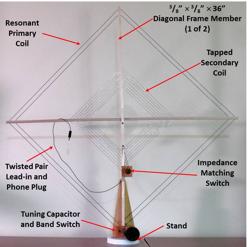
Figure 1.  A Passive, Resonant, Transformer-Coupled Loop Antenna for Shortwave

Figure 2 is a schematic diagram of the antenna.  Cd (in red) is the distributed capacitance of the primary coil, L1.  This is not tunable capacitance, but it still contributes to the resonance; likewise, the 15 pf minimum capacitance of C1.  By adding C2, the minimum total capacitance can be lowered to greatly increase the upper range of the antenna. S1 is the ‘band switch.’  It shorts out the series capacitor, restoring the maximum low frequency.
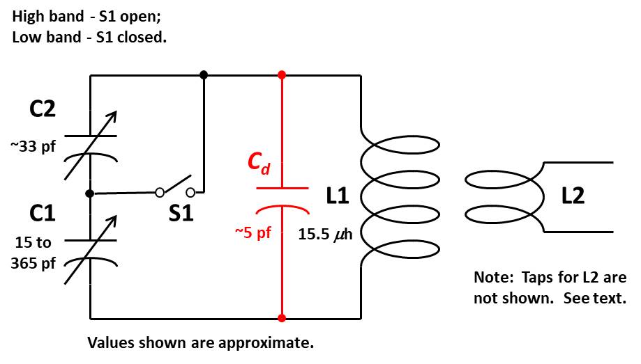
Figure 2.  Schematic Diagram

Frame – The frame is made from 3/8”-square basswood or poplar dowel (see Specialized Parts).  Two pieces, each 36” long, have been predrilled at ½” intervals to accommodate the primary and secondary coil wire (think of a tennis racket).  It is a good idea to drill holes along the length of each dowel – more than you will need. You may decide to change things later on, and drilling holes in an assembled antenna is not easy.  Also the two dowels are notched in their centers to fit together. See Figure 3 and Figure 4. The clear plastic disk in Figure 4 is a packing disk from a spindle of CDs; it is cemented to the square dowels, and used to hold them at right angles.  Any rigid, light-weight material will do.
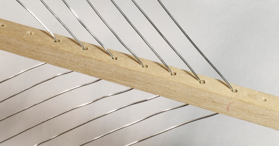
Figure 3. Square Dowel Showing 1?2” Hole Spacing and Lacing of Secondary Coil
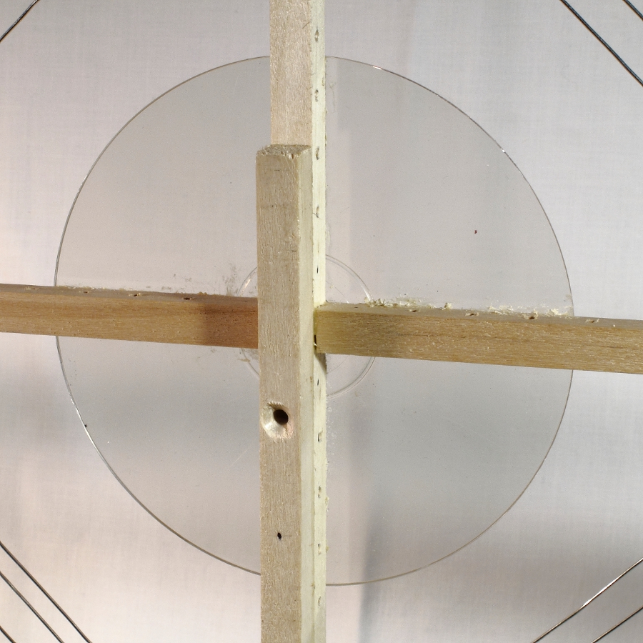

Figure 4. Cross Members Notched and Square Dowel Reinforcement

Primary Coil – With a coil size 36” in diameter, you likely won’t be able to get more than two turns of wire to resonate at frequencies up to 12 MHz.  This takes into account the precautions described above to minimize unusable capacitance.  AWG 22 stranded, insulated wire was used to lace this coil; ensure the dowels remain at right angles with one another.  Note that one set of holes in the dowel is skipped between the first and second turn.

Tuning Capacitor – Almost any salvaged variable capacitor can be made to work.  For a typical 2-gang unit, the gangs can be connected in series through the common rotor sections and metal frame with the stator terminals of each gang used as the outer terminals.  This will create a lower minimum capacitance as described above.

For the antenna described here, a single-gang, 365-pf capacitor (see Specialized Parts) was used with a fixed mica capacitor in series.  The minimum capacitance of the variable capacitor is nominally 15 pf. Figure 5 shows the capacitor assembly for the primary circuit. Components are mounted on a perforated circuit board, which, in turn, is mounted to the bottom of the vertical square dowel.  A portion of the base can be seen at the rear. A large diameter tuning knob is suggested, as the peak tuning for a properly constructed loop will be very sharp and require a delicate touch. As an option, I have used a planetary reduction mechanism on other antennas to give an 8:1 ratio with the capacitor shaft.

You may notice at high frequencies that the antenna is somewhat unstable with body contact of the knob or around the tuning capacitor.  This is because the resonant circuit is operating at a very high L/C ratio with capacitance at just a few picofarads. Body capacitance will tend to detune the antenna.  It may be useful to extend the knob 2 or 3 inches from the tuning capacitor with an insulated shaft.

Figure 5.  Capacitor Assembly

Secondary Coil – The secondary coil operates at low impedance to feed the lead-in.  There are two extremes governing the size of the secondary coil. A coil which is too small will not pick up much of the magnetic field generated by the primary circuit at resonance.  On the other hand, a secondary coil which is too large will overcouple or load the primary circuit. This will reduce the Q, or sharpness of the tuning.

The secondary coil is 16” diagonal at the largest turn and consists of 7 turns of AWG 20 buss wire.  Buss wire was used so the coil can easily be tapped after the 1st, 2nd, 3rd, 4th, and 6th turn.  The 7th turn is not currently used.  A tapped coil will provide better impedance matches to the lead-in when the antenna is used through a wide frequency range.  The taps are selected with a rotary switch. The taps are connected so that the outer turns are used first, and inner turns connected as needed.  It is important that unused turns remain unconnected (free) rather than shorted. See Figure 6.
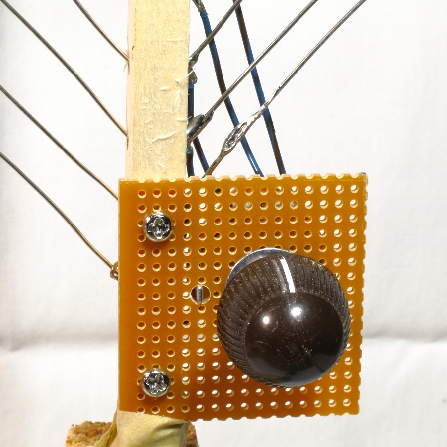
Figure 6.  Secondary Coil Switch

Lead-in – A twisted pair of AWG 22 stranded wire is used as the lead-in.  This will be more flexible than coax. The lead-in should be kept as short as possible and twisted tightly so it will not pick up any signal by itself.  This is important at shortwave frequencies. A twisted pair can be fabricated from two lengths of wire with one set of ends anchored in a vise, while the remaining ends are twisted in the chuck of a hand drill.  Most portable radios are equipped with a standard 1/8” phone jack at the external antenna connection point.  So, this antenna is terminated with a 1/8” phone plug.

Base – There is nothing special about the base.  Your only guidance should be to make it as stable as possible.  Since the frame is light, most of the weight will be at the bottom with the capacitor assembly and other parts.  That helps stability. This antenna uses a 5” plastic jar lid for the bottom. Keep the base small, as the antenna will likely be operated on a desk or table.

Operation

The antenna is intended to operate in close proximity to the radio, such as on a desk or table.  There must be sufficient space to rotate the loop laterally. As described, this antenna has a range of 2.6 MHz through 12.3 MHz with a band overlap around 8 MHz.  Depending on your selection of capacitors, your range and overlap may be slightly different.

  1. Tune the receiver to a desired frequency.
  2. Set the band switch on the antenna to the corresponding band.
  3. Tune the antenna capacitor to resonance (peak signal).
  4. Rotate the secondary switch to the position of maximum signal strength.  Begin with the fewest turns (generally one) in the secondary.
  5. It may be necessary to repeak the primary circuit.

Repeat the procedure to test operation of the upper or lower band.

Unlike similar loops for long and medium wave reception, this antenna is not especially responsive to direction for peak or null signal reception.  However, you will find it very useful to reduce or possibly eliminate locally produced noise. Simply rotate the antenna on its base.

Modification

The basic concept for this antenna can easily be extended to higher or lower frequencies.  Removal of the inner turn of the primary will significantly raise the upper frequency; whereas, adding turns will increase the lower range.  Note that the lacing of the primary coil skips one set of holes in the square dowels between the first and second turn. This minimizes distributed capacitance between turns.  This separation should be maintained if additional turns are added to lower the operational frequency.

Specialized Parts

Some sources for square wood dowel and single-gang 365 pf variable capacitors are listed below.  The author does not endorse any of them. Prices for similar capacitors vary widely.

Square wood dowel:

Variable capacitor (365 pf):


Bob, thank you so much for sharing this excellent, detailed tutorial. Although I don’t have the exact same variable capacitor, I have all of the other components to make this antenna. I will have to put this on my Social DX bucket list! Thank you again!


Do you enjoy the SWLing Post?

Please consider supporting us via Patreon or our Coffee Fund!

Your support makes articles like this one possible. Thank you!