Shortwave listening and everything radio including reviews, broadcasting, ham radio, field operation, DXing, maker kits, travel, emergency gear, events, and more
Many thanks to SWLing Post contributor, Dave Gahimer (K9ZCE) for the following guest post:
Small Magnetic Loop Antenna with Broadband Amplifier for SDR Reception
by Dave Gahimer (K9ZCE)
Those with limited space, or antenna restrictions, might find a small 1 meter loop antenna a solution.
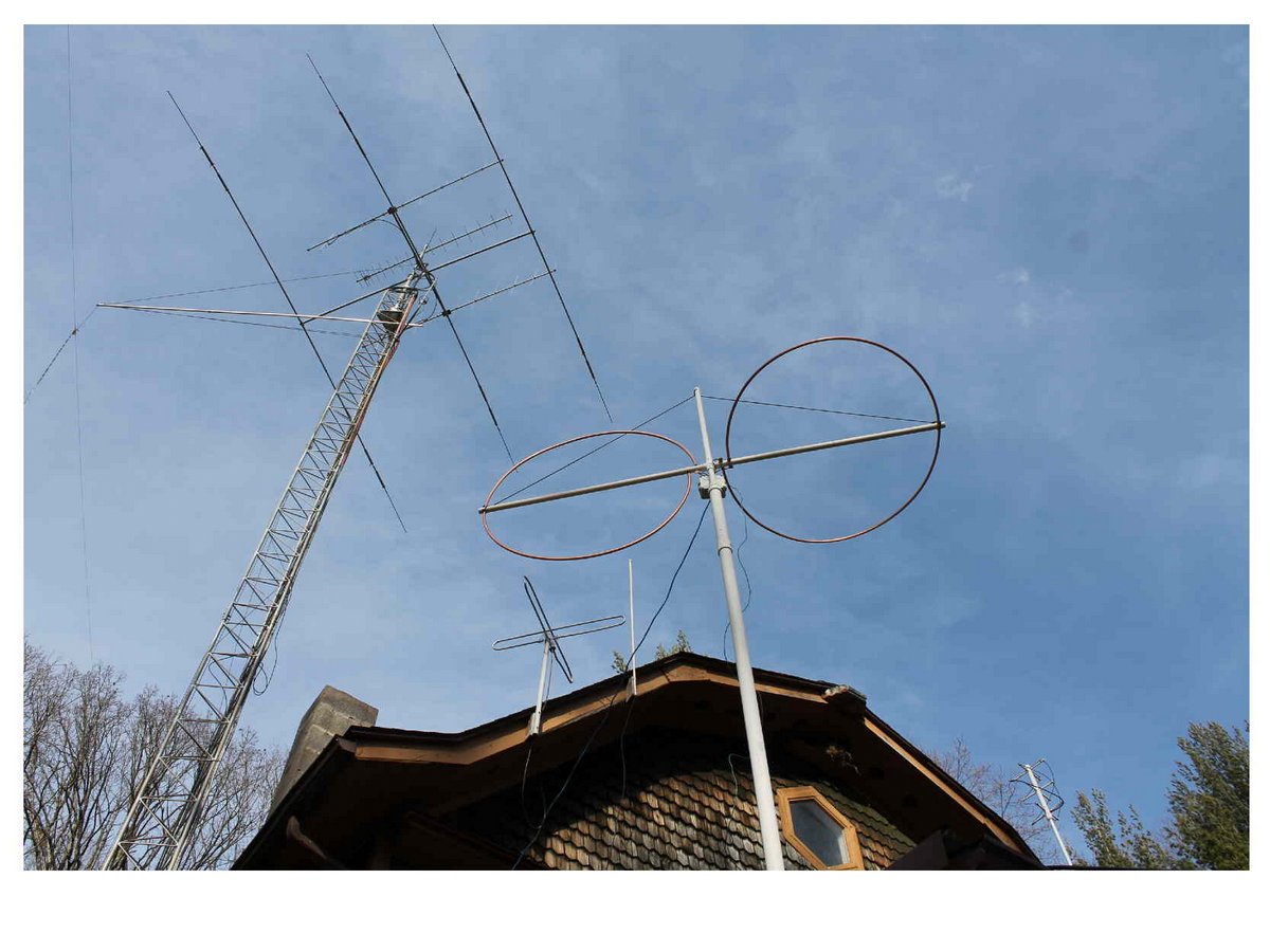
My son lives in an apartment. One Loop leaning against a wall gives him acceptable reception with the SDRPlay RSP on the ground floor–2nd or 3rd level flats should have very good reception.
Ten meters off the ground outside should give reception equal to any SWL antenna. We all with SDRs fight the image problem. Normal resonate ham band antennas show too strong reception of unwanted bands/stations. Did I mention noise? Loops are well known for –6 db noise reduction.
Then there is the possibility of SDR chip damage from your 1.5 KW station! In researching Loops we came across LZ1AQ. A Brilliant design /engineer (http://www.lz1aq.signacor.com/). Deep reading sometimes, but a great understanding of what makes a good receiving loop antenna.
Those who chase DX know that sometimes fading is caused by the signals’ polarization changing in the Ionosphere. Having both vertical and horizontal loops, and the ability to combine both signals diminishes this fading problem. Being able to filter the powerful, commercial FM transmitters diminishes image problems. Clipping strong signals at the antenna from very near powerful antennas/transmitters could save the SDR receiver from damage.
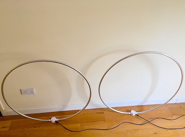
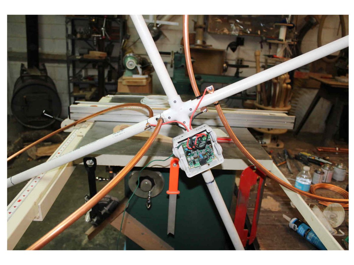
My son Ted and I built three, one meter loops from soft ½ inch copper plumbing tubing. One for his apartment, two for my crossed loops antenna. We weather proofed the Copper from corrosion by coating with outdoor clear spar varnish. We shaped the circle by drawing the tubing around a round glass top patio table.
The soft copper loop in held by white PCV plastic plumbing pipe. 1” or 1.25 inch schedule 40. Be careful to check that the PVC is schedule 40, thick wall. The thin wall pipe is not strong in the wind and will crack when you try to drill it.
Drill up to a 3/8 hole for the ½” copper tube to go through, then file out to fit. Here are some photos (click to enlarge):
Check out these links (all courtesy of LZ1AQ) to acquaint yourself with the loop construction and amplifier installation:
Many SDR receiver owners have seen improved noise and Image reduction by placing the plastic cased SDR unit on a small shielded/ grounded case.
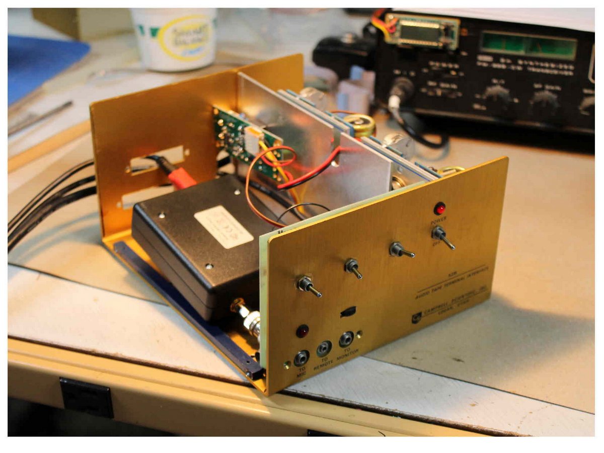
The Amp needs 12VDC from in the shack. The Amp has two relays that you can switch, from in the shack, to select Vertical or Horizontal loops, or a dipole. The loop amp connects back to the shack via a shielded Cat 5 cable, Make sure you get shielded CAT 5 to reduce noise pickup. Make sure you provide an adequate good Ground below the antenna, less noise pickup and lightening protection.
Have fun!
Dave, K9ZCE
Retired from EE Dept @ Rose-Hulman Institute of Technology
Terre Haute, Indiana
Thank you so much, Dave!
Readers: yesterday I saw Dave’s loop antenna photos on the SDRplay RSP Facebook page. I was fascinated by his horizontally/vertically oriented loops and asked if he would write up a short guest post. He kindly obliged in a matter of hours!
If you have an antenna project you’d like to share, please contact me. So many SWLs and ham radio operators live in areas with restrictions and pervasive RFI–projects like Dave’s can revive one’s radio life!
Many thanks to SWLing Post contributor, Jerry Popiel, for the following guest post:
A MW DXing Powerhouse Mini FSL Antenna
by Jerry Popiel
In late February 2016 I completed construction of a modified version of Gary DeBock’s excellent 3 inch Mini FSL design (click here to view).
This new antenna is nothing short of a AM DXing powerhouse with unbelievable sensitivity for receiving stations across the entire AM Bandwidth both day and night. The tuning of stations is razor sharp and it has stunning nulling qualities. Consultation assistance was provided from DXing experts Steve Ratzlaff and Gary DeBock on the project.
Construction Details:
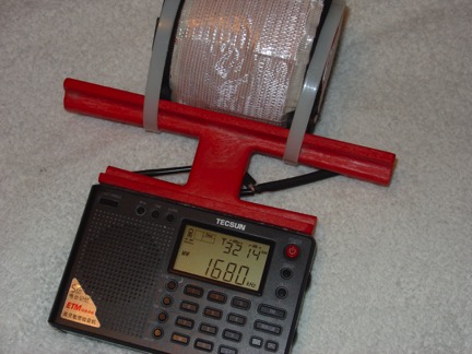
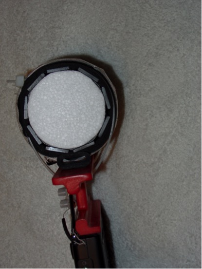
The Antenna was constructed using 9 – 100 mm Ferrite Bars wound on a 2.75 inch diameter x 4 inch styrofoam cake dummy form custom made by in Vancouver, B.C. Canada – ([email protected]) for $3.50 plus shipping.
The Coil wire consisted of 38 turns of high gain 660/46 Litz Wire. (Note: As can be seen 38 turns of the thicker Litz Wire left only 5/8” of room on each side of the Styrofoam Form to wire wrap the coil to the ruler frame. A longer Form ie 5” long would work much better for this build).
The insulation spacer used was 2 layers of 1/8 inch Aerotape self adhesive tape which also helped hold the 100 mm Ferrite Bars onto the Styrofoam Coil Form. Inductance measured 356 uH using a DM 4070 Meter which is well within the requirement of over 300 uH for AM Band Reception.
Side View Of 9-Bar FSL Antenna with 2.75” Diameter Styrofoam Cake Dummy.
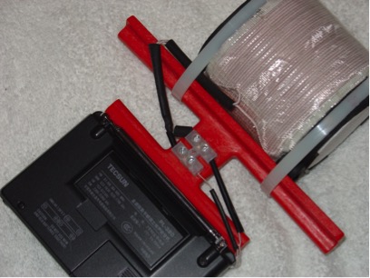
Because of the extra thickness of high gain 660/46 Litz Wire which is a bit too big to solder to the inside terminals of the Tecsun PL-380 Radio, a 2 Position Terminal Block was superglued to the outside of the Ruler Frame to act as an interface connection point.
2 Position Terminal Block Superglued To Back Of Antenna Frame
Testing Results:
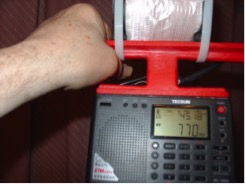
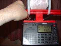
Both daytime and evening AM station captures have been spectacular. Stations as far away as KKOB / 770 kHz Alberquerque, New Mexico 1130 Miles from here in Winnipeg, Manitoba, Canada have been received. Country music station WSM / 650 kHz in Nashville, Tennessee 1082 miles distant is a daily evening pickup.
Station KKOB / 770 kHz Alberquerque, New Mexico 1130 Miles distance.
Station WSM / 650 kHz in Nashville, Tennessee 1082 miles distance.
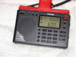
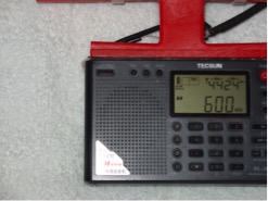
Two Stations Received At 600 kHz 90 Degrees apart at the same time:
The amazing Nulling and Razor Sharp Tuning quality of this FSL was demonstrated when 2 stations at 600 kHz were received at the same time by rotating the Radio with attached FSL 90 degrees. In the North / South direction Station KSJB / Jamestown, North Dakota (219 miles distant) was received with a strong signal strength of 50 / 23. Then by rotating the Radio 90 degrees to the East / West direction Saskatoon, Saskatchewan station CJWW (442 miles distance) was captured with a similar strong signal strength of 44 / 24.
600 kHz Station KSJB / Jamestown, North Dakota.
600 kHz Station CJWW / Saskatoon, Saskatchewan.
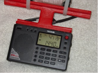
Daytime Reception of 600 Watt Station 137 Miles Distant:
A major daily AM reception capture during the afternoon illustrating the amazing sensitivity of this antenna is 600 Watt station KKXL Sports Radio 1440 kHz (137 miles).
All Indoor Reception – For Now!
Due to winter conditions here in Winnipeg, all of the amazing station reception captures in this report were done inside the House facing towards the South window. Fortunately the red ruler platform sides can he used as handles when pointing the radio in the direction of best reception. Exciting times are ahead to see how well this mini 3” FSL will perform outdoors for likely even better AM DXing.
Summarizing:
The design of this new FSL Antenna attached to the Tecsun PL-380 Ultralite radio by Gary DeBock is a major breakthrough in AM DXing since the Radio is attached to the FSL. This new FSL Antenna needs to be constructed to be really appreciated. The application described here requires a bit more skill to construct and is also heavier than the original construction – but at least it is portable. For beginners Gary’s original 3” FSL Heathkit Design is highly recommended and can be reviewed in his You Tube Video posted at: https://www.youtube.com/watch?v=VY9u8MReGjk
Thanks,
Jerry Popiel
Winnipeg, Manitoba, Canada
Thank you, Jerry! It’s amazing what performance you and Gary DeBock have gotten out of these homebrew FSL antennas! Thank you so much for taking the time to share your construction details and performance notes!
Many thanks to SWLing Post contributor, Mario Filippi (N2HUN) for the following guest post:
Maritime Broadcasts in RTTY, Sitor B, and NAVTEX.
By Mario Filippi, N2HUN
(All photos below are courtesy of the author. Click each image to enlarge.)
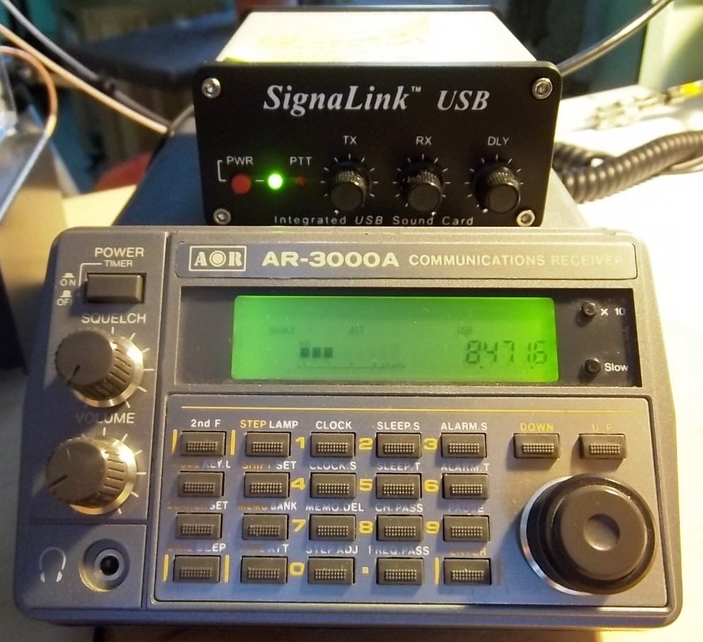
Non-voice high seas weather broadcasts and safety messages to mariners can be found by spinning your VFO dial to 8.472 MHz USB courtesy of WLO from Mobile, AL, which provides these transmissions continuously. Here on the East Coast it is received with regularity due to it’s strong signal.
Those of you who are neophytes to RTTY or just want to dabble then this is the place to be to try your hand at an old and venerable digital mode. The RTTY (RadioTeleTYpe) parameters used by WLO transmissions are 45.45 bauds, 170Hz shift. These are most commonly used by amateur radio ops too. If you’ve roamed the bands for RTTY signals you’ll find that most are encrypted with a few exceptions, one of which is WLO which is transmitting continuously.
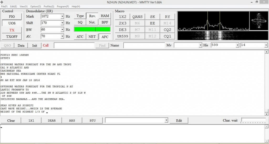
Tabletop SW radio set to WLO; SignaLink USB links radio to computer for decoding.
On 8.472 MHz you’ll receive weather information from different latitude/longitudes, along with other pertinent information to mariners such as high seas pirates (not radio pirates!) and naval maneuver areas that are important for ships to avoid. It makes for interesting copy.
To decode RTTY signals you’ll need a shortwave receiver with a BFO (Beat Frequency Oscillator), a way to pipe your radio’s audio into your computer’s sound card, and decoding software. There are several RTTY software packages out there, free, and my favorite is MMTTY. More info on MMTTY is at: http://hamsoft.ca/pages/mmtty.php . Old timers will find this software a snap to use, but newcomers will have to fiddle with the controls to get the decoding going. Below is a snapshot of MMTTY decoding a typical weather broadcast.
MMTTY dashboard with WX info. Cross-like indicator on upper right aids in tuning signal.
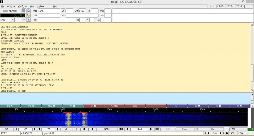
Another software available for decoding RTTY is Fldigi. Again, you’ll have to input the correct RTTY parameters such as baud rate and shift into the program along with adjusting your VFO carefully. It takes practice, but when the decoding is successful you’ll see Fldigi doing it’s thing as shown below. Both MMTTY and Fldigi have waterfalls displaying a visual image of the received signal. With practice you’ll be able to distinguish the different common RTTY shifts just by looking at the waterfall.
Fldigi in action with split screen; RTTY text above, waterfall below.
Now to Sitor B (Simplex Teletype Over Radio Mode B), another non-voice mode we can use to decode WLO transmissions. Sitor B sounds a lot like RTTY to the human ear, but requires different decoding software. WLO transmits weather information via Sitor B immediately after RTTY transmissions, switching back and forth, which makes for even more fun! Software that decodes Sitor B is available on the ‘Net as free downloads. One is MultiPSK, the other is YaND.
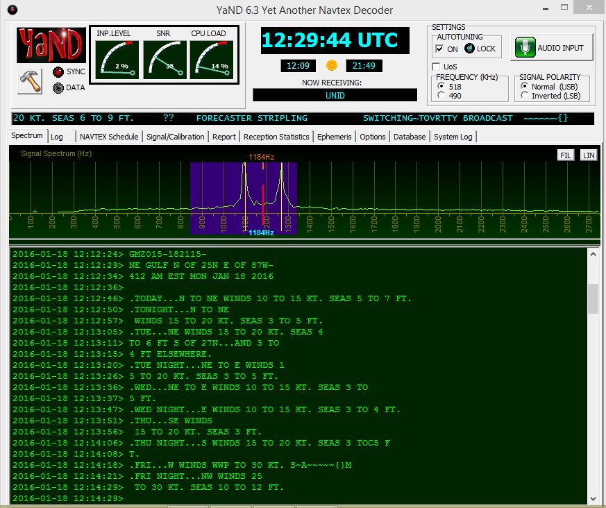
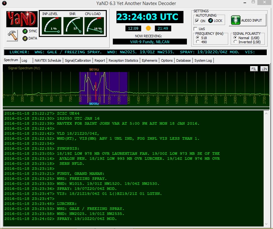
I like YaND (Yet another Navtex Decoder) which is used to decode NAVTEX (Navigational Telex) transmissions commonly found on 490 KHz and 518 KHz, but it works well for decoding Sitor B. There is a difference in the way messages are processed in NAVTEX versus Sitor B and for further information perform a Google search. But the fastest and easiest way to decode Sitor B transmissions from WLO is to fire up YaND. Below is a recent NAVTEX HF broadcast capture.
WLO HF WX broadcast for NE Gulf on 1/18/16 .
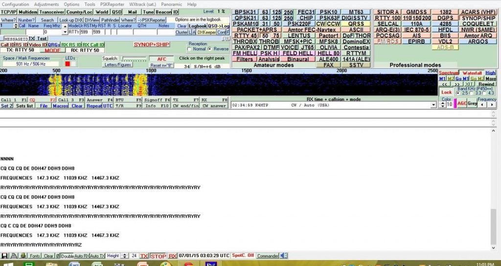
Well, hopefully some of you will be inspired to check out maritime weather/safety information found on WLO using RTTY/Sitor B/NAVTEX software. However, RTTY can also be found on the ham bands and on shortwave frequencies. Several RTTY stations from Germany are found on frequencies such as 11.039MHz and 14.467MHz. Their weather information format is quite different and will give you an idea of European weather conditions and allow you to practice your German. When not sending weather info they run a RTTY message loop below at 50bauds/425Hz shift.
German RTTY station with message loop. Deciphered via MultiPSK.
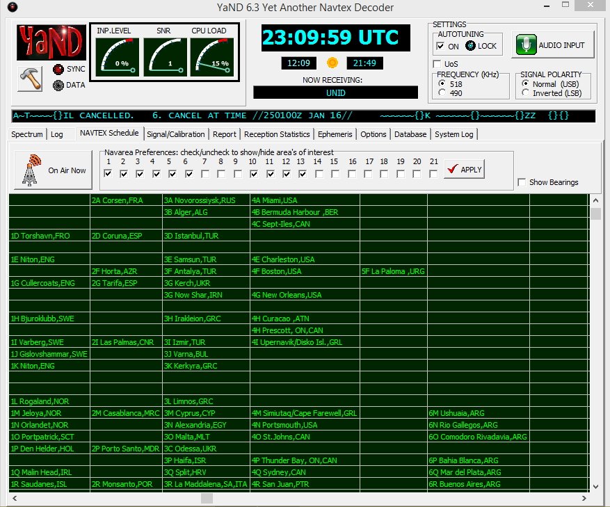
In closing, make sure to also check out the NAVTEX broadcasts found just below the AM broadcast band on 490 and 518 KHz; using YaND or MultiPSK you’ll be able to receive these transmissions, but remember you’re not on HF, you are on MW (medium wave), where signal distances are shorter and present a greater reception challenge. YaND software has a NAVTEX broadcast schedule built in as seen below; you have to identify your specific NAVAREA or navigational area, then look at the times and frequencies to determine when to listen in. My QTH is in NAVAREA 4. Lots of interesting information is passed in these NAVTEX transmissions so listen in and have fun!
YaND NAVTEX schedule for various NAVAREAS.
NAVTEX on 518 KHz from station VAR-9, New Brunswick, CAN. Messages begin with “ZCZC.
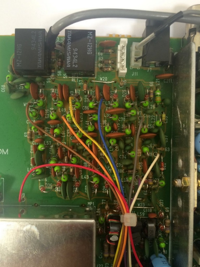
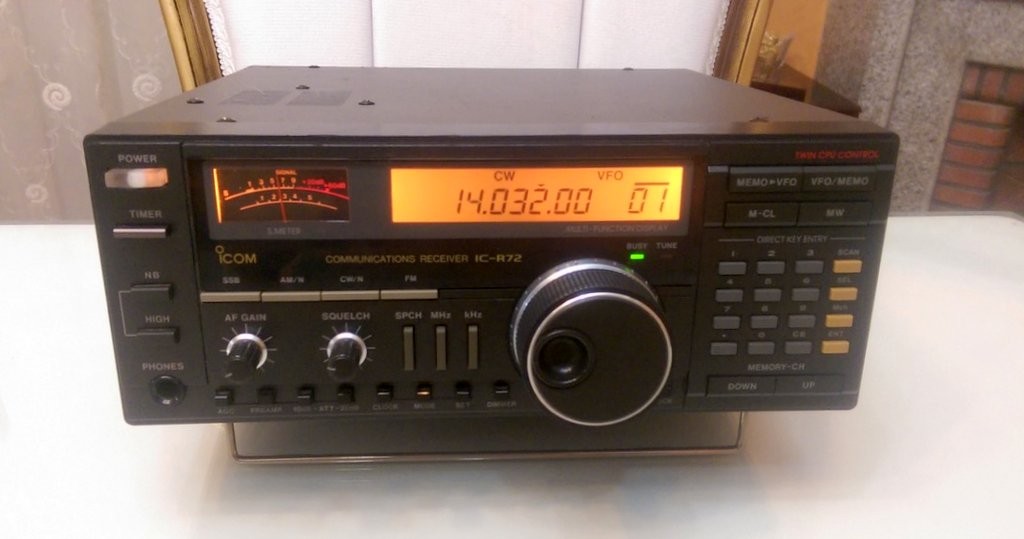
In this post I’m going to tell you how I repaired my Icom IC-R72 receiver. Although it’s about a specific device, the logic and methodology applies to all radios.
I bought an Icom R72 from a friend for about $200. At first, I just checked 7.0MHZ (40 meter band) and 21.0MHZ (15 meter band) and it was OK. After some time, I tried to listen to some ham radio on 20 meters (14.0MHZ) and it was deaf! I checked everything: antenna connectors, balun…everything.
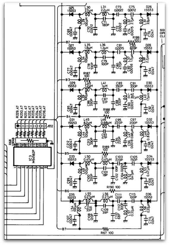
With some trial and error, I found out that it was deaf from 11-15 MHz. With the help of the members of “Icom R72” Yahoo Group, I found one of the usual suspects: bandpass filters’ switching diodes.
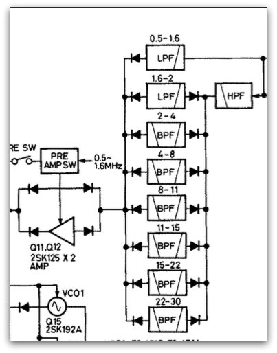
I took a look at the service manual and apparently this radio uses multiple bandpass filters for different frequency ranges.
As you see in the above picture (grabbed from service manual), one of the bandpass filters is for 11-15 MHz range–that’s the range where my radio was deaf.
Note that there are multiple ways to test that a radio is deaf at a frequency. One of the simplest ways: connect an antenna or even a long wire to the antenna socket of radio. The noise level should increase; if not, there’s a problem.
After testing diodes with a multimeter, I found out that D31 is faulty. Almost all multimeters have a diode-test functionality.
I replaced it. The original diode was 1SS53, but I used a 1N4148 which is very common and found everywhere. Now I have a working radio! 🙂
If you have a radio that’s deaf at a frequency range, there is probably a problem in bandpass filters.
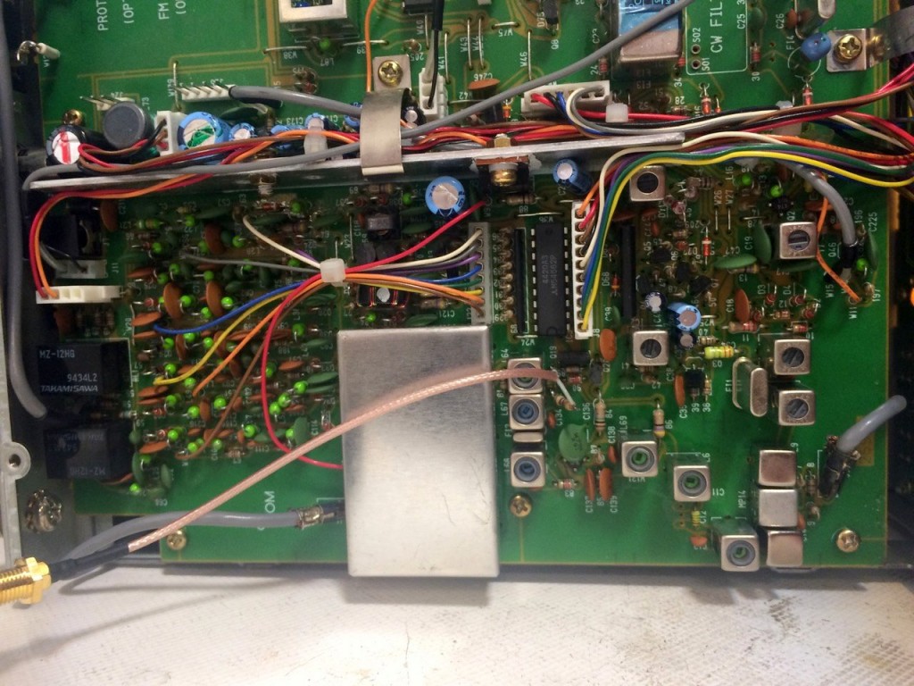
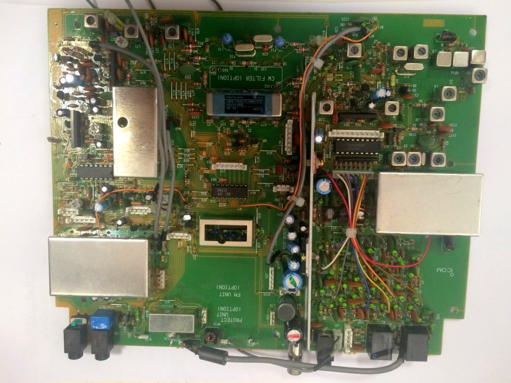
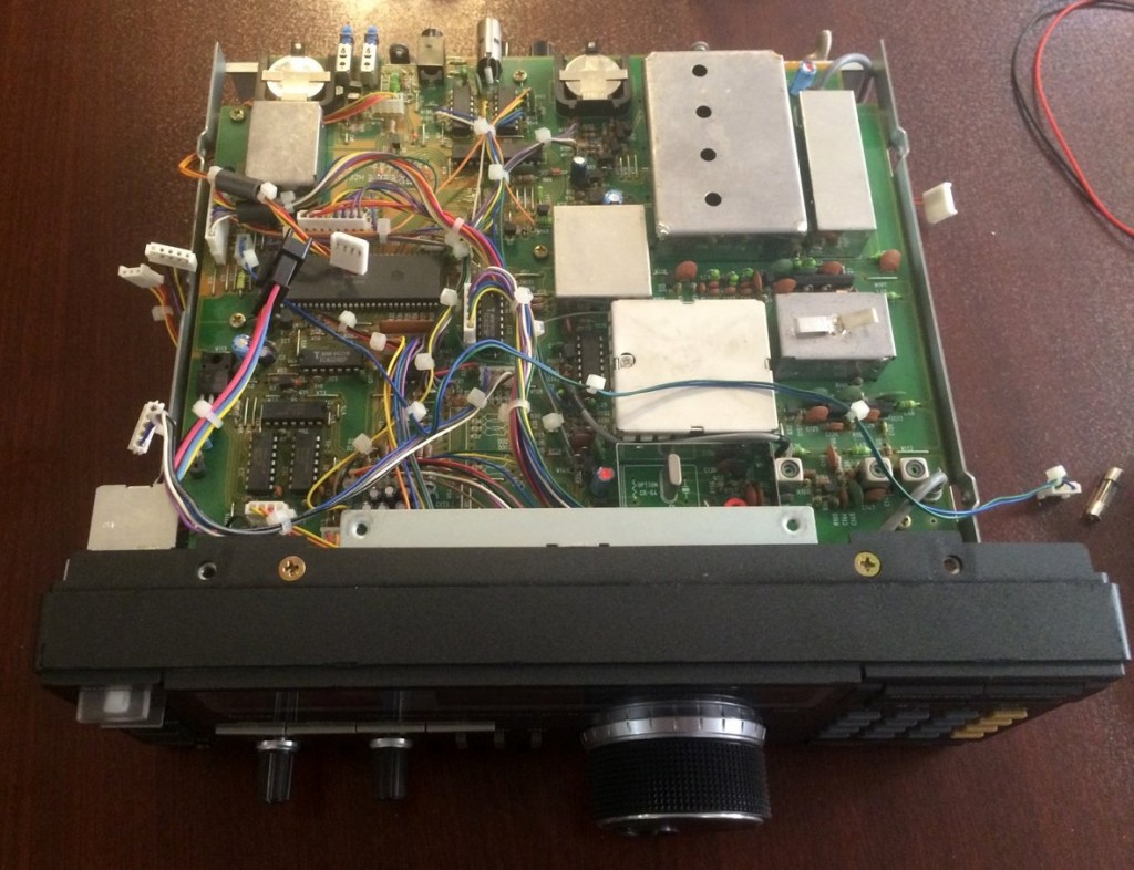
Here are some internal pictures of my Icom IC-R72:
I should thank my friend and electronics mentor, Saeed (EP2LSH) who always helps me in my electronics adventures.
Mehdi Asgari, the author of this post, is a regular contributor to the SWLing Post. Mehdi lives in Tehran and is an active member of the EP2C amateur radio club.
Dave’s beacon is located on 13,558 kHz–he would love your reception reports. Dave notes in his post:
“If you hear the SPT beacon on 13,558 kHz, please send a report – either to the e-mail address listed on my QRZ account [look up call AA7EE], or as a comment underneath this post. Reception reports will be very eagerly received. One gentleman in Seminole County, FL, reported that the area around the SPT frequency was a cacophony of noise in his area, and he stood no chance of hearing it. Those kinds of reports are useful too. If you put your own HiFER beacon on the air, do introduce yourself on the LWCA message board, and John can include you on the list of known active HiFER beacons.“
Readers: let’s give Dave some reception reports! Though I live on the opposite side of North America, I will certainly be listening!
Dave, thanks again for publishing such an informative and detailed post! You’ve inspired me to build my own beacon.
Many thanks to SWLing Post contributor, London Shortwave, who is kindly sharing this guest post–a brilliant article he recently posted on his own website.
I’m very grateful: one of the most common questions I’m asked by readers is how to cope with the radio interference so many listeners and amateur radio operators experience in high-density, urban areas. If this is you, you’re in for a treat–just keep reading:
Dealing with Urban Radio Interference on Shortwave
Shortwave radio listening is an exciting hobby, but for many of us city dwellers who either got back into it recently or tried it out for the first time not long ago, the first experience was a disappointing one: we could barely hear anything! Station signals, even the supposedly stronger ones, were buried in many different types of static and humming sounds. Why does this happen? The levels of urban radio frequency interference, or RFI, have increased dramatically in the last two decades and the proliferation of poorly engineered electronic gadgets is largely to blame. Plasma televisions, WiFi routers, badly designed switching power adapters and Ethernet Over Powerlines (also known as powerline network technology, or PLT) all severely pollute the shortwave part of the radio spectrum.
Does this mean we should give up trying to enjoy this fascinating medium and revert to using the TuneIn app on our smartphones? Certainly not! There are many angles from which we can attack this problem, and I shall outline a few of them below.
Get a good radio
The old adage “you get what you pay for” certainly holds true even when it comes to such “vintage” technologies as shortwave radio. Believe it or not, a poorly designed receiver can itself be the biggest source of noise on the bands. That is because many modern radios use embedded microprocessors and microcontrollers, which, if poorly installed, can generate interference. If the receiver comes with a badly designed power supply, that too can generate a lot of noise.
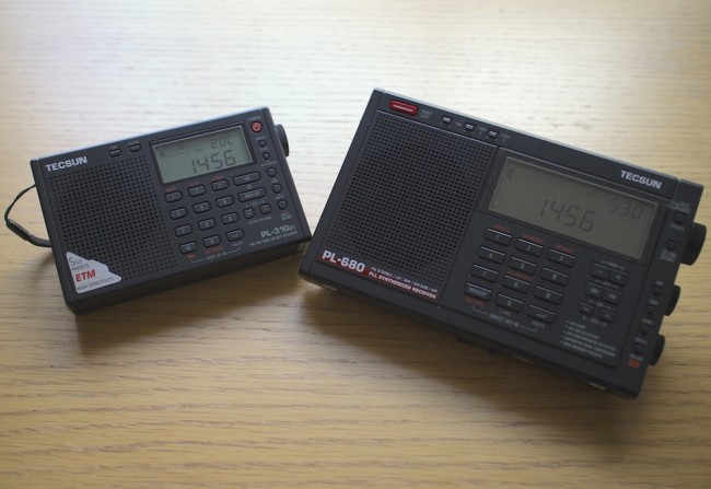
So how does one go about choosing a good radio? SWLing.com and eHam.net have fantastic radio review sections, which will help you choose a robust receiver that has withstood the test of time. My personal favourites in the portable category are Tecsun PL310-ET and Tecsun PL680. If you want a desktop radio, investigate the type of power supply it needs and find out whether you can get one that generates a minimal amount of noise.
It is also worth noting that indoor shortwave reception is usually best near windows with at least a partial view of the sky.
Tecsun PL310-ET and Tecsun PL680, my two favourite portable shortwave radios.
Identify and switch off noisy appliances
Many indoor electrical appliances generate significant RFI on the shortwave bands. Examples include:
Plasma televisions
Laptop, and other switching-type power supplies
Mobile phone chargers
Dimmer switches
Washing machines / dishwashers
Amplified television antennas
Halogen lighting
LED lighting
Badly constructed electrical heaters
Mains extension leads with LED lights
Identify as many of these as you can and switch them all off. Then turn them back on one by one and monitor the noise situation with your shortwave radio. You will most likely find at least a few offending devices within your home.
Install an outdoor antenna
If you have searched your home for everything you can possibly turn off to make reception less noisy but aren’t satisfied with the results, you might want to look into installing and outdoor antenna. That will be particularly effective if you live in a detached or a semi-detached property and have a garden of some sort. Of course, you will need a radio that has an external antenna input, but as for the antenna itself, a simple copper wire of several metres will do. An important trick is making sure that the noise from inside your home doesn’t travel along your antenna, thus negating the advantage of having the latter installed outside. There are many ways of achieving this, but I will suggest a configuration that has worked well for me in the past.
Fig.1 Schematic for an outdoor dipole antenna.
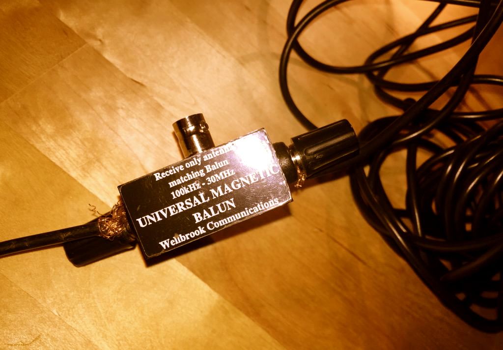
I have used a three-terminal balun (positioned outdoors), and connected two 6 metre copper wires to its antenna terminals to create a dipole. I then connected the balun to the radio indoors through the feed line terminal using a 50? coaxial cable. In the most general terms, the current that is generated in the antenna wires by the radio waves flows from one end of the dipole into the other, and a portion of this current flows down the feed line into your radio. The balun I have used (Wellbrook UMB130) is engineered in a way that prevents the radio noise current from inside your house flowing into the receiving part of the antenna.
Wellbrook UMB130 balun with the feed line terminal disconnected
Antenna preselectors
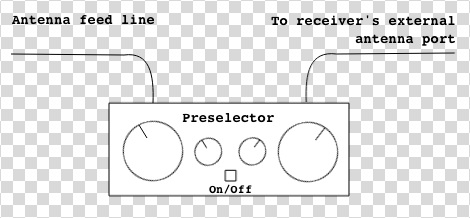
There is a catch with using an outdoor antenna described above — the signals coming into your radio will be a lot stronger than what would be picked up by the radio’s built-in “whip” antenna. This can overload the receiver and you will then hear many signals from different parts of the shortwave spectrum “mixing in” with the station you are trying to listen to. An antenna preselector solves this problem by allowing signals from a small yet adjustable part of the spectrum to reach your radio, while blocking the others. You can think of it as an additional tuner that helps your radio reject unwanted frequencies.
Fig.2 Schematic of a preselector inserted between the outdoor antenna and the receiver
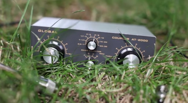
There are many antenna preselectors available on the market but I can particularly recommend Global AT-2000. Although no longer manufactured, many used units can be found on eBay.
Global AT-2000 antenna coupler and preselector
Risk of lightning
Any outdoor antenna presents the risk of a lightning strike reaching inside your home with devastating and potentially lethal consequences. Always disconnect the antenna from the receiver and leave the feed line cable outside when not listening to the radio or when there is a chance of a thunderstorm in your area.
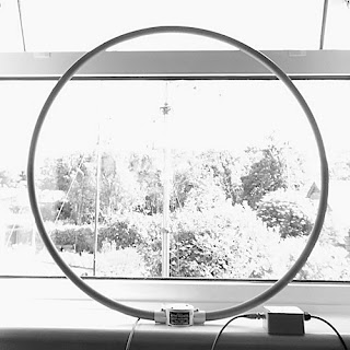
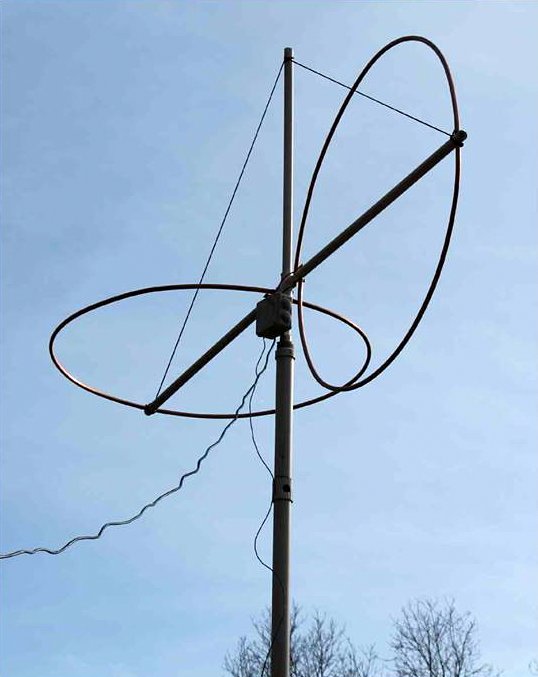
Get a magnetic loop antenna
A broadband loop antenna (image courtesy of wellbrook.uk.com)
The outdoor long wire antenna worked well for me when I stayed at a suburban property with access to the garden, but when I moved into an apartment well above the ground floor and without a balcony, I realised that I needed a different solution. Having googled around I found several amateur radio websites talking about the indoor use of magnetic loop receive-only active antennas (in this case, “active” means that the antenna requires an input voltage to work). The claim was that such antennas respond “primarily to the magnetic field and reject locally radiated electric field noise”[*] resulting in lower noise reception than other compact antenna designs suitable for indoor use.
Interlude: signal to noise ratio
In radio reception, the important thing is not the signal strength by itself but the signal to noise ratio, or SNR. A larger antenna (such as a longer copper wire) will pick up more of the desired signal but, if close to RFI sources, will also pick up disproportionately more of the local noise. This will reduce the SNR and make the overall signal reading poorer, which is why it is not advisable to use large antennas indoors.
The other advantage of a loop antenna is that it is directional. By rotating the loop about its vertical axis one can maximise the reception strength of one particular signal over the others, once the antenna is aligned with the direction from which the signal is coming (this is termed “peaking” the signal). Similarly, it is possible to reduce the strength of a particular local noise source, since the loop is minimally sensitive to a given signal once it is perpendicular the latter’s direction (also known as “nulling” the signal).
It is further possible to lower the effect of local noise sources by moving the antenna around. Because of the antenna’s design, the effect of radio signals is mostly confined to the loop itself as opposed to its feed line. Most local noise sources have irregular radiation patterns indoors, meaning that it is possible find a spot inside your property where their effects are minimised.
Many compact shortwave loop antennas require an additional tuning unit to be attached to the loop base (much like the preselector described above) but broadband loops do not. Wellbrook ALA1530S+ is one such antenna that is only 1m in diameter, and it was the one I chose for my current apartment. I was rather impressed with its performance, although I found that I need to use a preselector with it as the loop occasionally overloads some of my receivers when used on its own. Below is a demo video comparing using my Tecsun PL680’s built-in antenna to using the radio with the Wellbrook loop.
As you can hear, there is a significant improvement in the signal’s readability when the loop is used.
Experiment with a phaser
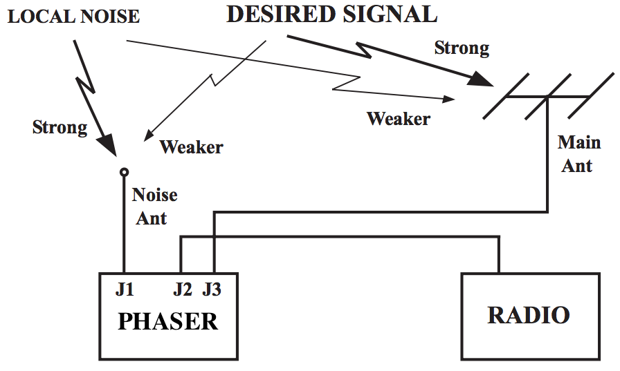
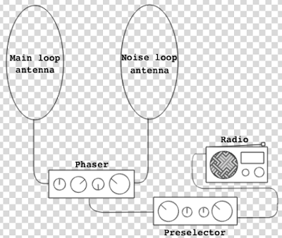
Although the loop antenna dramatically reduces the levels of ambient RFI getting into the radio, I also have one particular local noise source which is way too strong for the loop’s nulling capability. Ethernet Over Powerlines (PLT) transmits data across domestic electrical circuits using wall socket adapters, as an alternative to wireless networking. It uses the same frequencies as shortwave, which turns the circuits into powerful transmitting antennas, causing massive interference. One of my neighbours has PLT adapters installed at his property, which intermittently become active and transmit data. When this happens, it is not merely noise that is generated, but a very intense data signal that spreads across the entire shortwave spectrum, obliterating everything but the strongest stations underneath. Fortunately, a mature piece of radio technology called antenna phasing is available to deal with this problem.
Fig.3 The principle of antenna phaser operation (adapted from an original illustration in Timewave ANC-4’s manual)
Signal cancellation using phase difference
A phaser unit has two separate antenna inputs and provides one output to be connected to the radio’s external antenna input. The theory of phase-based signal cancellation goes roughly as follows:
The same radio signal will arrive at two different, locally separated antennas at essentially the same time.
The phase of the signal received at the first antenna will be different to the phase of the same signal received at the second antenna.
This phase difference depends on the direction from which the signal is coming, relative to the two antennas.
The phaser unit can shift the phases of all signals received at one antenna by the same variable amount.
To get rid of a particular (noise) signal using the phaser unit:
the signal’s phase at the first antenna has to be shifted by 180° relative to the signal’s phase at the second antenna (thus producing a “mirror image” of the signal received at the second antenna)
its amplitude at the first antenna has to be adjusted so that it is the same as the signal’s amplitude at the second antenna
the currents from the two antennas are then combined by the unit, and the signal and its mirror image cancel each other out at the unit’s output, while the other signals are preserved.
Noise sampling antenna considerations
To prevent the possibility of the desired signal being cancelled out together with the noise signal — which can happen if they both come from the same direction relative to the antennas — one can use the set-up illustrated in Figure 3, where one antenna is dedicated to picking up the specific noise signal, while the other is geared towards receiving the desired broadcast. That way, even if the phases of both the noise and the desired signals are offset by the same amount, their relative amplitude differences will not be the same, and thus removing the noise signal will not completely cancel out the desired signal (though it will reduce the latter’s strength to some extent).
It is possible to use any antenna combination for phase-based noise signal cancellation. However, one has to be careful that, in the pursuit of removing a specific noise source, one does not introduce more ambient RFI into the radio system by using a poorly designed noise-sampling antenna. After all, the phaser can only cancel out one signal at a time and will pass through everything else picked up by both antennas. This is particularly relevant in urban settings.
For this reason, I chose my noise sampling antenna to also be a Wellbrook ALA1530S+. The additional advantages of this set-up are:
It is possible to move both loops around to minimise the amount of ambient RFI.
By utilising the loops’ directionality property, one can rotate the noise sampling loop to maximise the strength of the noise signal relative to the desired signal picked up by the main antenna loop.
Two Wellbrook ALA1530S+ antennas combined through a phaser
And now onto the phaser units themselves.
Phaser units
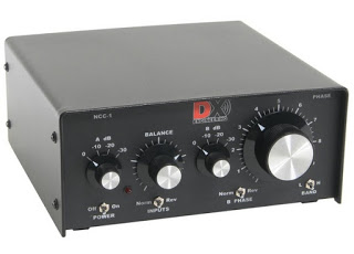
DX Engineering NCC-1 (image courtesy of dxengineering.com)
I have experimented at length with two phaser units: the MFJ 1026 (manual) and DX Engineering NCC-1 (manual). Both solve the problem of the PLT noise very well, but the NCC-1 offers amplitude and phase tuning controls that are much more precise, making it a lot easier to identify the right parameter settings. Unfortunately this comes at a price, as the NCC-1 is a lot more expensive than the MFJ unit. As before, a preselector is needed between the phaser and the radio to prevent overloading.
Below is a demo of DX Engineering NCC-1 at work on my neighbour’s PLT noise. I have chosen to use my SDR’s waterfall display to illustrate the nefarious effect of this type of radio interference and to show how well the NCC-1 copes with the challenge.
Cost considerations
Fig.4 Final urban noise mitigation schematic
It would be fair to say that my final urban noise mitigation set-up, shown in Figure 4, is quite expensive: the total cost of two Wellbrook antennas ($288.38 each), a DX Engineering phaser ($599.95) and a Global AT2000 preselector ($80) comes to $1257. That seems like an astronomical price to pay for enjoying shortwave radio in the inner city! However, at this point another old saying comes to mind, “your radio is only as good as your antenna”. There are many high-end shortwave receivers that cost at least this much (e.g. AOR AR7030), but on their own they won’t be of any use in such a noisy environment. Meanwhile, technological progress has brought about many much cheaper radios that rival the older benchmark rigs in terms of performance, with Software Defined Radios (SDRs) being a particularly good example. It seems fair, then, to invest these cost savings into what makes shortwave listening possible. You may also find that your RFI situation is not as dire as mine and you only need some of the above equipment to solve your noise problems.
Filter audio with DSP
If you have implemented the above noise reduction steps but would still like a less noisy listening experience, consider using a Digital Signal Processing (DSP) solution. There are a number of different approaches and products available on the market, and I shall be reviewing some of them in my next post. Meanwhile, below are two demo videos of using DSP while listening to shortwave. The first clip shows the BHI Compact In-Line Noise Elimination Module at work together with a vintage shortwave receiver (Lowe HF-150). The second video compares using a Tecsun PL-660 portable radio indoors on its own and using the entire RFI mitigation set-up shown in Figure 4 together with a DSP noise reduction feature available in the SDR# software package, while using it with a FunCube Dongle Pro+ SDR. As a side note, it is worth remembering that while DSP approaches can make your listening experience more pleasant, they can’t recover what has been lost due to interfering signals or inadequate antenna design.
Set up a wireless audio relay from your radio shack
The above RFI mitigation techniques can result in a rather clunky set-up that is not particularly portable, confining the listener to a specific location within their home. One way to get around this is by creating a wireless audio relay from your radio shack to the other parts of your house. I did this by combining the Nikkai AV sender/receiver pair and the TaoTronics BA01 portable Bluetooth transmitter:
Head for the outdoors!
So you have tried all of the above and none of it helps? As a last resort (for some, but personally I prefer it!), you can go outside to your nearest park with your portable radio. After all, if shortwave listening is causing you more frustration than joy it’s hardly worth it. On the other hand, you might be surprised by what you’ll be able to hear with a good receiver in a noise-free zone.
Acknowledgements
Many of the above tricks and techniques were taught to me by my Twitter contacts. I am particularly grateful to @marcabbiss, @SWLingDotCom, @K7al_L3afta and@sdrsharp for their advice and assistance over the years.
Thank you–!
What I love about my buddy, London Shortwave, is that he didn’t give up SWLing just because his home is inundated with radio interference–rather, he saw it as a challenge. As you can see, over the years, he has designed a system that effectively defeats radio interference.
I also love the fact that he uses an even more simple approach to defeating RFI: he takes his radio outdoors. A kindred spirit, indeed.
I encourage all SWLing Post readers to bookmark and search London Shortwave’s website. It’s a treasure trove for the urban SWL. We thank him for allow us to post this article in its entirety.
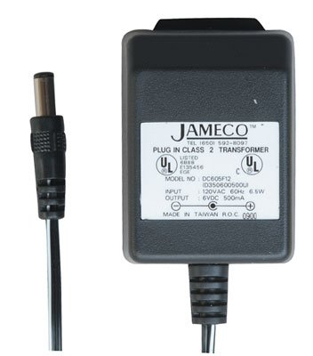
“Google the following: “Jameco linear wall transformer”, and you’ll find a suitable non-switching replacement.
Jameco still has a number of linear transformers in their catalog at reasonable prices. I haven’t bought anything from them in many years but when I dealt with them frequently a number of years back they were always reputable.”
When you purchase a replacement power supply, you must make sure that several properties match that of the device it will power, else you could cause damage.
There are four properties you need to match: voltage, rated current, polarity and tip size.
Voltage
Most consumer electronics are powered by and rated for 4.5, 5, 9, 12, or 13.8 volts DC. Of course, there are exceptions. It is important that you match the required voltage exactly. Most radios and electronic devices display their required voltage and voltage tolerance on the unit itself, on the supplied switching power supply, and/or in the owner’s manual.
Rated Current
Like voltage, rated current is usually displayed somewhere on the device, existing power supply or in the owner’s manual. Current is usually indicated in amps (A) or milliamps (mA). Unlike voltage, rated current on your power supply does not have to match the device exactly. You simply need to make sure the power supply meets or exceeds your radio’s required current.
For example, if your radio requires 800 mA (or .8 A) and you find a power supply rated for 500 mA, you should not use it. If you find a power supply rated for 2 amps (or 2000 mA), it exceeds the 800 mA rating, so you’re good to go!
Unlike voltage, your electronic device or radio will only draw the amount of current it needs from the power supply.
Polarity
Click here to read more about tip polarity. (Source: WikiPedia)
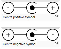
You’ll need to determine if your radio requires a plug with a positive or negative tip (a.k.a. center conductor).
Fortunately, manufacturers have long used standard symbols to make polarity obvious (see image).
You’ll typically find a polarity symbol printed on the back of your radio, near the plug-in point, in the owner’s manual or on the back of the existing wall adapter.
Note: Be very careful matching polarity! Some radios and electronic devices are not properly protected against reverse polarity; damaged can occur immediately after supplying voltage with incorrect polarity.
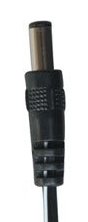
Tip/plug size
You need to make sure that the inner diameter and outer diameter of a replacement wall adapter will match that of your existing adapter.
This can be the most difficult property to match.
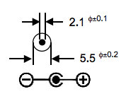
Occasionally, radio manufacturers will actually specify the tip size in their owner’s manual, spec sheets, or on the product page of their website. I’ve even had luck calling manufacturers and asking a technician for the plug size.
Specification sheets will typically indicate plug dimensions with an illustration.
Otherwise, you can always measure the existing power supply tip (both inner and outer dimensions) using calipers.
Once you have those dimensions, finding the appropriate replacement power supply is quite easy. Indeed, companies like Jameco provide specification sheets (click here for an example) that indicate dimensions for each power supply they sell.


 In this post I’m going to tell you how I repaired my Icom IC-R72 receiver. Although it’s about a specific device, the logic and methodology applies to all radios.