Guest Post
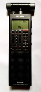
The Tecsun PL-368: An Everyman Review
By Robert Gulley
I entitled this review an “Everyman” review because, while I am far from “normal” (just ask any of my friends!), I am not a hard-core SWL. I am a hard-core amateur radio operator perhaps, but only for the last decade(+). I have been casually listening to shortwave radio for about 50 yrs. So, my perspective on this radio comes from someone who cut his teeth on a Realistic DX-160 (still love those radios!), progressing through various desktop and portable radios, to three of my current favorites, the FRG-7, the Sangean 909X2, and the Sony 7600GR. Of course, this doesn’t count some vintage WWII-era radios and earlier, but they are favorites for other reasons.
Now, the purpose of this little reflection on equipment is to say all radios have their place in the pantheon of shortwave radios, and no one radio “does it all.” The Tecsun radio, I believe, fills a very specific niche in the radio world, and it is excellent for those purposes. It does not, however, rival other radios whose goals are different, such as ones designed around sound fidelity, digital signal processing, SDR capability etc.
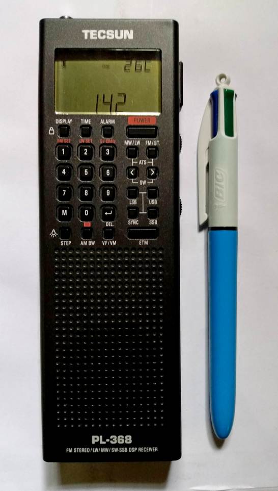
What this radio does do is present a very capable radio in an ultra-small package, designed to fit easily for travel and for survival/emergency situations, or for armchair operation. That middle one may surprise you, so allow me to explain.
I have a previous model of this radio (GP-5/SSB still available) sold by CountyComm, which was modified from Tecsun’s stock production PL-365, to have features suitable for government use. This has become a rather popular radio for preppers because of those modifications. The idea behind this radio as a compact piece of kit for government embassy people was to have something which could be easily concealable, operated with one hand, and have a wide range of reception capabilities. Of course, good reception of shortwave, AM, and FM bands was considered a must. You can look at the CountryComm website to find out specific features of the modified units if interested, as that radio, or the PL-365, are not the subject of this review.
While not a real “prepper” myself, I was intrigued by the AM broadcast reception capabilities due to the plug-in ferrite antenna, and also liked the idea of the small footprint. In actual use I found the radio to be quite versatile, a good performer, but rather awkward to use as there was no quick way to get to specific frequencies, unless already programmed into a memory location. With no direct keyboard entry on the GP-5, going to random locations to channel surf was, for me, frankly a bit annoying.
 Enter the PL-368 which boasts a direct keyboard entry! Yes!! This one feature has taken the radio to a new level of performance which makes it a joy to use in this reviewer’s humble opinion. (Full disclosure, the unit I received for this review was provided by ANON-CO, and is the latest model after the recent firmware update incorporated by Tecsun. However, I have no other connection to ANON-CO or Tecsun, and my willingness to do the review is purely based on my previous purchase and experience with the CountyComm model.)
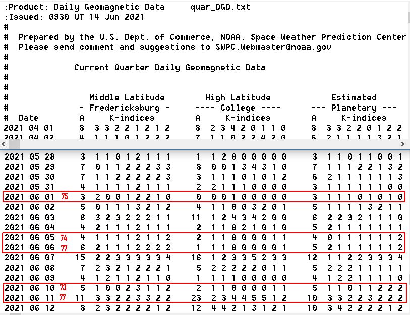
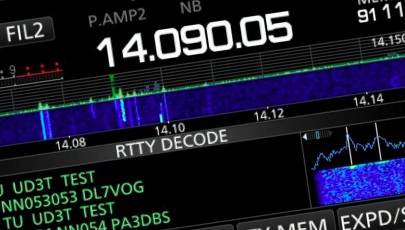
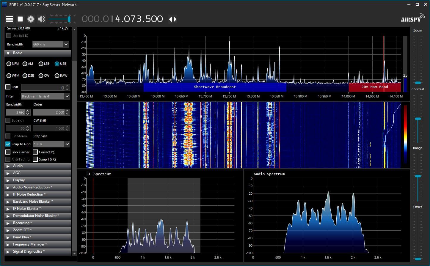
Despite having an unusual number of stormy days and nights here in the Midwestern U.S. recently, I have managed to enjoy some very productive listening opportunities with this little radio. For example, being an amateur radio operator, I appreciate the ability to listen in on the amateur frequencies now an again, and the recent ARRL Field Day afforded me the opportunity to really test out the radio’s USB/LSB reception capabilities, and its ability to dig out signals on a really crowded band. I was quite impressed both with its DSP and bandwidth capabilities and the reasonable clarity of the audio when tuning in various signals. Does it have the richness of audio that my Sangean 909X2 has? No, of course not. The speaker is much smaller in the PL-368, but it was quite listenable. Likewise, listening to various nets on 80 meters was quite acceptable with the built-in antenna, where noise and local interference are common gremlins on any radio.
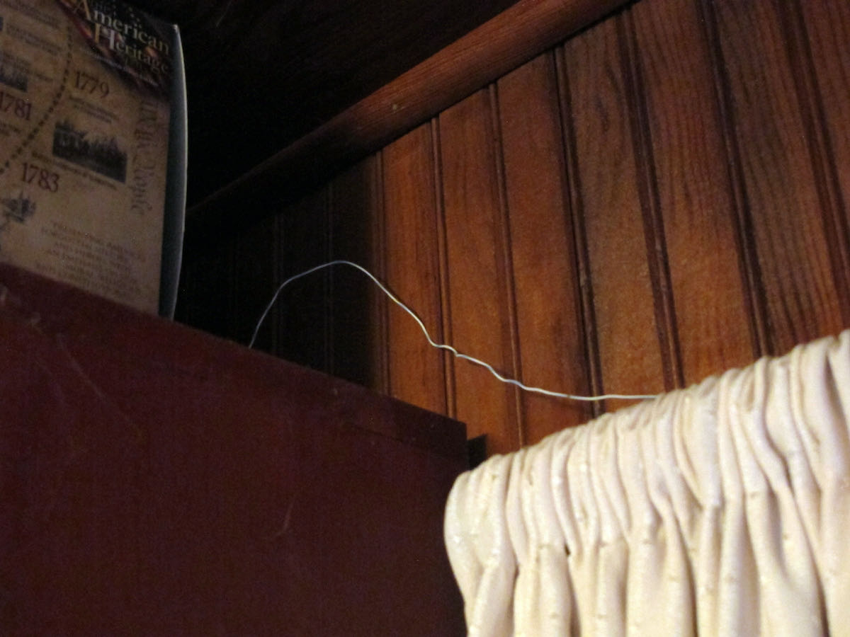
For shortwave stations I found the radio to be quite sensitive just using the built-in antenna, which is key to portable listening. If I have to attach an external antenna, my mobility becomes limited, and I might as well just listen to one of my desktop radios. Some reception examples include: NHK World Radio 9560, Helliniki Radiophonia Voice of Greece 9420, WRMI relay of KSKO 89.5’s Paul Walker from McGrath Alaska on 7780 (beamed to east coast U.S., as well as on 7730 beamed to west coast, Hawaii, and South Pacific).
Of course, reception of CRI, Radio Havana Cuba, and numerous religious broadcasts were heard on all the usual places. I also listened to WWV signals at various locations, my go-to initial band reception check, as well as listening to HF aircraft broadcasts, military planes training on 11175 (USB), and maritime weather broadcasts. While I did not try digital mode reception such as FT8 with WSJT-X from the headphone jack, I have no doubt I would have been able to monitor these stations on various bands easily as the signals were immediately recognizable. The same holds true for CW reception.
Operational Notes
For a thoughtful, in-depth review of many technical aspects of this radio Dan Robinson has written an excellent piece on the PL-368, along with an updated review of the latest firmware’s effect on the radio. One aspect worth mentioning in my experience with this radio is that, unlike Dan, I did not find an issue with changing sensitivity when touching/holding the radio versus the radio standing on its own. Your mileage may vary, of course, so this goes in the “for what it’s worth” category. Maybe this issue has been resolved in later production runs? Or maybe my capacitance is running low and I need more electrolytes<grin>!
Like Dan, I found the SYNC detection of USB/LSB to be marginal at best, mostly making the signals harder to hear. On the upside, standard reception was quite good, and I did not experience significant fading most of the time.
Below are some of the hidden keyboard functions as listed, provided by Anna of ANON-CO, but I wanted to mention a feature I have either forgotten when using my GP5 CountyComm model, or which has been added (sorry, I don’t have access to the GP5 right now as it is packed away due to a recent move in progress). When “speed tuning” as I call it (turning the tuning dial quickly) with the “step” selected to the smallest increment on SW, what starts as increments of 10Hz will jump to 50Hz at a time after a few moments. This helps in trying to quickly latch on to a signal when increments of 10 are not necessary. The tuning will revert to 10Hz units when stopped for a few seconds.
Now for some undocumented features:
Switch between internal ferrite rod and whip on AM (MW & LW)
- Select the MW or LW band.
- Press and hold key ‘3’ for about 2 seconds.
When the display briefly shows “CH-5” this means that the device is set to MW/LW reception using the telescopic antenna. The display shows MW (or LW) and SW on the left side of the screen.
When the display briefly shows “CH-A” this means that the device is set to MW/LW reception using the internal ferrite antenna. The display shows only MW (or LW) on the left side of the screen.
Adjusting the maximum volume level
Select the frequency band, then press and hold key ‘7’ for 2 seconds until a number is displayed. At this moment, rotate the [ TUNING ] knob to adjust and press the key ‘7’ again to save and exit.
Firmware Version
In power-off mode, press and hold [ VF/VM ] for 0.5 seconds until all characters on the display are shown, then wait a few seconds until the firmware version is briefly displayed in the middle of the display.
Extend SW-range for European setting (1621-29999 kHz)
- In power-off mode, press and hold the [ 3 ] key to set the MW tuning steps to 9kHz.
- Select the SW band, and then press and hold the [ 5 ] key for 10 seconds to enable/disable the SW frequency extension. The starting point of the SW frequency range will become 1621 or 1711 kHz.
Some Nitpicks (There had to be some, right?!)
I wish the batteries were still standard AA units instead of the flat rechargeable unit. This is merely a personal preference, but as a radio designed for carry-anywhere usage, I like a radio to use batteries I can pick up anywhere if needed. I tend to use rechargeable AA and AAA batteries anyway, but I like knowing I can use ubiquitous alkaline batteries available at almost any store in a pinch.
I suspect the change was made to allow for more space for the direct keypad entry, and that is definitely a tradeoff I am willing to make!
On a related note, the recharging port uses the USB micro-b connector which I have found in cell phones, tablets, etc. to be a weak point as cables often seem to go bad, or the connector itself gets damaged. The larger mini-b would be my preference, but hey, again, that’s a nitpick.
Finally, the case does appear to be a little thin which makes me wonder how it might survive if dropped or knocked off a table. This is not a deal-breaker by any means, but something to consider when carrying it around or when packing it for a trip. It may survive quite well, but that’s a test I don’t want to try out just to see what happens.
 Final Thoughts
For me, as a casual shortwave listener, I look for several things in a portable radio. I want true portability – if a so-called portable radio must be tethered to an external antenna to work decently, chances are I am not going to use it often – my various desktop models attached to outdoor antennas will always out-perform a portable. I also want a simplified layout of controls. I do not want to dig through menus, have be a contortionist to work the buttons/controls, or carry a manual with me to find out how to use the radio each time because the controls are confusing. I also want reasonable audio and clarity, or the ability to fine-tune a signal to minimize adjacent signals.
I find the PL-368 does for me what I want a portable to do and does it reasonably well. Is it the best portable out there? No. Is it a benchmark radio? No. But it is extremely portable, easily handled with just one hand, and its reception capabilities put it far above some other portables I have used. If you are looking for something which can easily fit into a pocket, bag, or purse, this radio is great. If you want a radio which performs well over a wide range of signals using the built-in antenna, this radio fills the bill. And if you want true USB/LSB, along with good bandwidth options in your portable, this is a great choice. Cheers!
(edit, July 23, 2021: an additional “hidden” feature to be included in the shipping version not included in this reviewed unit is an SSB calibration capability – definitely a plus! — Robert)


")