Many thanks to SWLing Post contributor, Dan Robinson, for the following guest post and review:
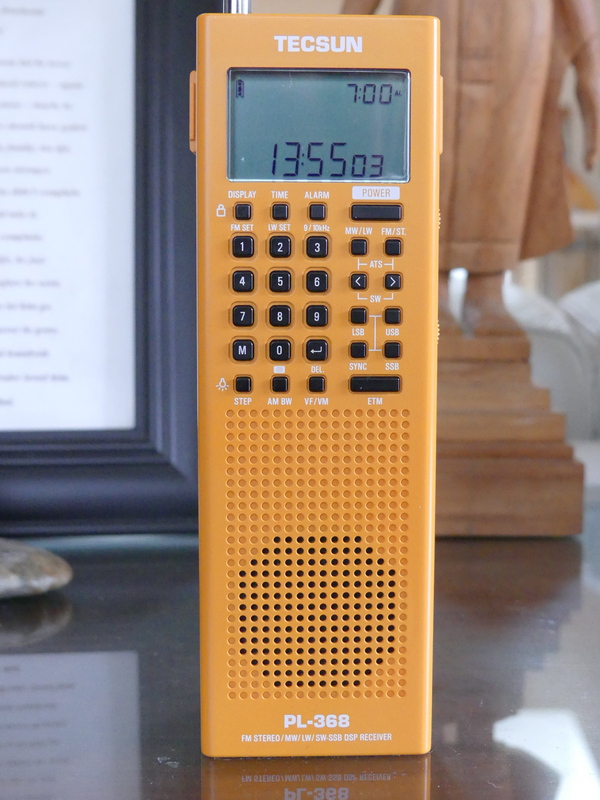 Tecsun PL-368: Large Receiver Features In Smaller Vertical Handheld
by Dan Robinson
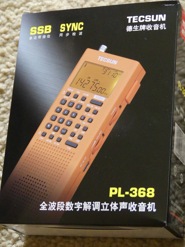
It was back in 2020 that the first photos surfaced online of the PL-368 – posted on Facebook by someone attending the electronics fair in Shanghai, China.
Photos showed the successor to the PL-360/365 receivers – and also the PL-990, successor to the PL-880, as well as the new king of the hill for Tecsun, the larger dual speaker H-501.
Things looked promising, and it was pretty exciting. Tecsun designers upgraded the PL-365 which had become a favorite of preppers and SWLs, but which was hobbled by the lack of a keypad, to the re-named PL-368.
The PL-365 and PL-360 before it were plagued by the problem of being overly sensitive to the touch – when holding the radio, reception was fine, but remove your hand and signal levels plummeted. Usually, a full hand grip was necessary to obtain full sensitivity and any variation in grip reduced sensitivity – this was noticed mostly in shortwave mode.
Previous 360/365 models were known for the included small rotatable ferrite
AM amplified antenna which performed miracles in nulling mediumwave stations – for those who still like to listen to the AM band. The 368 also comes with this additional ferrite antenna.
And the 365/360 (which were and still are sold by CountyComm as the GP-5) used AA batteries, making it very easy to find replacements anywhere the radio is being used in the field. Tecsun changed that on the 368.
After the photos appeared, I contacted Benny Zhao, who had posted them on one of the Facebook groups and asked if he could send me a sample of the PL-368. He obliged and a 368 was sent on its way.
The radio was sent without the BL-5C flat lithium battery which was prohibited in postal shipments. It took a long, long time (3 months, apparently the package was sent by snail mail) but it finally arrived here and I have been putting it through some tests.
The PL-368 that I received has the notation “2020.12 VER 1” so it’s clearly a first version from 2020 production.
Like the models before it is a great, handy, portable to grab if you’re going on a trip. It is lighter than the older 360/365s. The change from three AA batteries to the flat BL-5C explains some of that. There is a heft to the older models that the 368 doesn’t have. I am not sure about differences in thickness of the 368 cabinet. Perhaps we will find out more from Tecsun (see notes below regarding issue of tapping the front of the 368 cabinet).
The 368 retains the two multi function adjustment wheels on the right side, one for Volume, the other for Tuning. These are also used for time and bandwidth control.
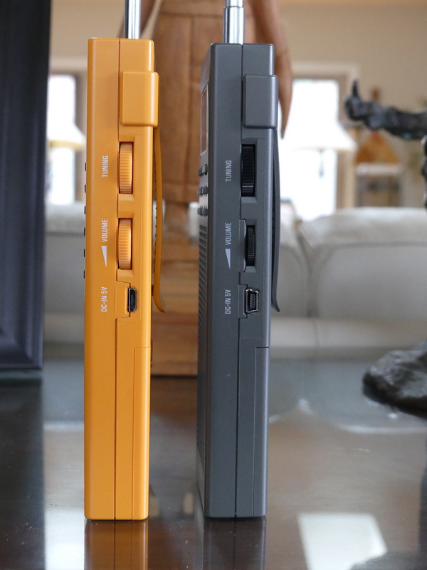
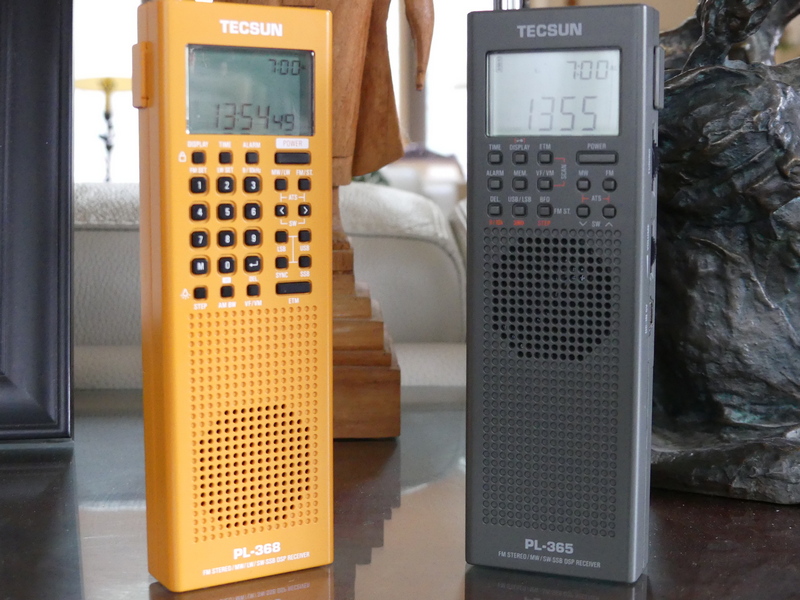
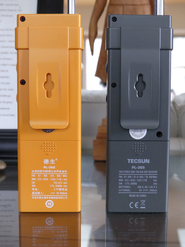
Tecsun PL-368 (left) and PL-365 (right)
On the 360/365 radios, I never found the tuning wheel approach to be particularly efficient since it was limited to a certain number of kHz per turn, either 5 or 1 kHz depending how fast you turned.
On the 368 it appears you can obtain up to 40 kHz from a single turn of the wheel, while on the 360/365 that was limited to 15 to 20 kHz depending on the speed you were turning.
Tecsun PL-368 (left) and PL-365 (right)
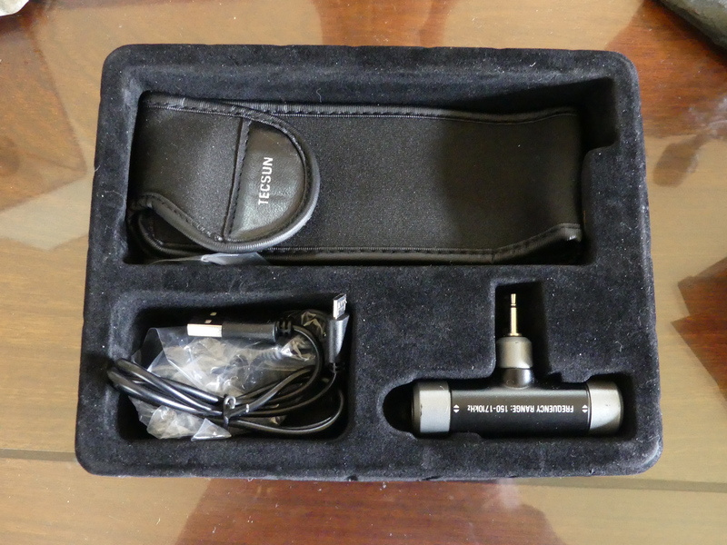
The antenna on the 368 is thinner, but 8 inches longer than the 360/365 models, and in the box you will find the included and very effective rotatable ferrite antenna for mediumwave that inserts in a jack on the top.
On the 368 the volume wheel has detents, whereas on the 360/365 the wheel had smooth turning.
We have gone from 14 buttons on the old PL-360/365 models to 28 buttons on the PL-368, including addition of the keypad.
UPGRADES
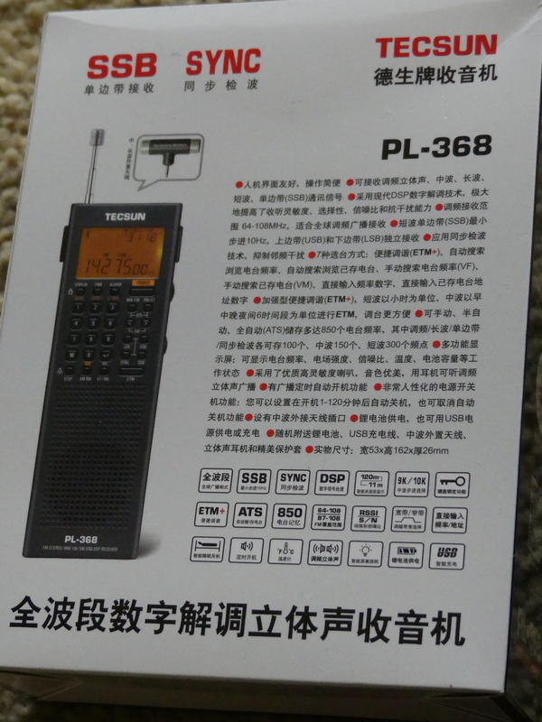
Tecsun has upgraded the 368 in line with improvements seen in the PL-990x and H-501 receivers. There are now adjustable bandwidths – a particularly useful tool. These bandwidths also operate in SSB, something that the new Sangean ATS-909×2 doesn’t offer. Bandwidths are: LW/MW 2.5, 3.5, 9.0 SW: 2.5, 3.5, and 5.0 SSB: 0.5, 1.2, 2.2, 3.0 and 4.0 kHz
Also in the 368 is now synchronous detection, a feature left off Sangean’s 909×2. And you get the same intelligent tuning features seen in the 909x/501x models as well as the previous PL-880.
Tecsun added a control that enables activation of the light – this is located on the same button as the Step control which adjusts the tuning steps.
The 368 display now has the ability to tune in 10 Hz increments, an overdue upgrade from the 360/365 models.
Charging of the BL-5C battery can be carried out by connecting a DC 5V/0.5A adapter to the micro-USB port on the side of the radio. The English manual notes that when charging, the charging time is displayed at the top right corner of the display while the “Charge” indicator flashes.
Adjustments for 9/10 kHz mediumwave, Longwave, and FM frequency range can be found on the 1, 2 and 3 keys.
The manual notes that in addition to the internal ferrite bar antenna, the external supplied MW/LW ferrite antenna can be connected to the antenna socket on top and rotated to obtain optimum reception.
Addition of the keypad makes the PL-368 far more useful than its predecessors for instantaneous frequency access. This was the major drawback of the 360 and 365 receivers. This can’t be emphasized enough.
This is a day versus night difference and vastly improves the attractiveness of the 368 over previous models.
There are 850 memory presets, 100 for FM/LW, 150 for MW, 300 for SW, and 100 each for SSB and SYNC.
ATS tuning, like the 990x and 501 receivers enables ATS within all meter bands by holding the [<] or within a selected meter band by holding the [>]. The manual also notes the ability to auto scan all stored stations within a frequency band or mode (SYNC/SSB) staying on each station for about 5 seconds before resuming.
The 368 has what Tecsun now calls Enhanced Tuning Mode (ETM+) – as explained in the manual, this allows auto tune and storing of FM, LW, MW and SW stations into ETM memory. Unlike ATS, scanned stations will not be stored into regular memory (VM) – in this way, when in a different city or country, ETM+ can be used to auto search new stations without overwriting any previously stored stations.
FM De-emphasis Time Constant – as explained in the manual, while receiving FM broadcasts, long pressing [4] will adjust the de-emphasis setting for Europe, Australia, Japan (and most other locations), or for Americas and South Korea.
Add Seconds to the Clock – with the device powered off, press and hold [8] to add seconds to the clock.
Sleep Timer – as with its predecessors, the 368 has a Sleep Timer, with an indicator on the LCD display.
Alarm – and like earlier models, there is also an Alarm function, which allows the radio to turn on at a preset time. It’s possible to select a specific frequency to be used with the Alarm.
RE-CALIBRATION – I have not been able to determine yet if the 368 has a re-calibration function as can be found on the PL-330, 909x, and H-501.
PROBLEMS
Let’s get one headline out to start: The 368, as with the 909x and H-501 all have the useful Synchronous Detection mode. However, SYNC continues to be hobbled, showing distortion and loss of lock.
As I have mentioned in reviews of the 330, 990x, and 501x any successful use of SYNC requires a delicate dance involving careful selection of various bandwidths while in SYNC mode and fine tuning.
The 368 manual contains 3 pages of explanation of SYNC noting that it can “eliminate distortion generated in the IF filter due to local fading, slight offset, modulation overshoot, as well as inter-channel interference and cross-talk modulation, and can also reduce noise interference.”
The problem with all of the Tecsun DSP chip receivers after the PL-880, which had a hidden SYNC feature that was the worst of the bunch, is the extent to which SYNC still suffers from distortion and loss of lock that renders the feature far less useful than it could be.
Ideally, one would want SYNC to match the capability achieved in such older receivers as SONY’s ICF-2010, SW-100S, SW-07, 7600GR. You’re not going to get that with Tecsun receivers.
Like its predecessors, the 368 is still sensitive to touch. I noticed this immediately on the old 360/365 receivers, especially when using the radios
at the beach. If I was recording a station on shortwave, and left for a few minutes, I would return to find that sensitivity had dropped because the radio was not still being held in the hand, which rendered the recording useless.
I am continuing testing of the 368 to try to determine if this issue has been reduced to any extent and will update this review with any further findings. This sensitivity issue is not specific to the 368 – it can be seen on other older and newer receivers.
Many older portables (the SONY ICF-SW55 comes to mind) were constructed with robust cabinets that were less sensitive to touch. Touching the whip antennas on some older receivers improved reception, while on others touching the whip antenna actually reduced sensitivity.
URGENT ATTENTION FOR TECSUN: My initial testing of this particular China market unit of the PL-368 – again, it is marked as December 2020 Version 1 production – identified an additional issue.
When in SSB modes or SYNC, tapping on any area of the keypad and LCD display produces a warbling/distortion effect in the audio. One can only surmise that this is attributable to insufficiently robust construction of the PCB board underneath.
(Video shows problem created when physically tapping front of PL-368 cabinet.)
This is NOT a problem seen with my PL-365 when it is in SSB mode.
I hope that Tecsun gives this the attention it needs and corrects the problem in future production runs.
SUMMARY
Were it not for the major problems detailed above, the PL-368 would be an automatic must-buy receiver in my book.
Addition of the keypad is a night and day improvement and when combined with additional features such as multi-bandwidth options and the still-to-be-perfected synchronous detection, the 368 would be a killer portable.
But as with the PL-330, 909x and 501x the problem with SYNC mode is still a major drawback on a feature that is supposed to lift Tecsun receivers out of the pack of portables that are on the market in 2021.
One can live with the issue of cabinet sensitivity – but the additional issue I identified where there is instability introduced when tapping on the front panel/keypad/LCD is a QC problem that simply must be addressed by Tecsun.
But as I have said in reviews of other Tecsun receivers, let’s back up a bit. Imagine if we had had portable receivers with the capabilities that these have, back in the 1960’s or 1970’s.
It’s one of the great ironies of the radio listening hobby, that in 2021 any company is willing to continue producing receivers of this caliber as use of shortwave by major broadcasters continues to decline.
The obvious other killer feature to include in portables such as this would be to somehow integrate DRM into them. However, I have a feeling that will never happen