Shortwave listening and everything radio including reviews, broadcasting, ham radio, field operation, DXing, maker kits, travel, emergency gear, events, and more
Radio Waves: Stories Making Waves in the World of Radio
Because I keep my ear to the waves, as well as receive many tips from others who do the same, I find myself privy to radio-related stories that might interest SWLing Post readers. To that end: Welcome to the SWLing Post’sRadio Waves, a collection of links to interesting stories making waves in the world of radio. Enjoy!
Experience in amateur radio can be a boon to the radio engineer
Starting in the 1920s and through the ’60s, almost every broadcast engineer was a licensed amateur radio operator. That has changed a bit, but the importance of being a ham has not.
Both environments involve getting an RF signal from Point A to Point B. But it is interesting to note that radio broadcast and amateur radio are similar and yet so different.
For those who don’t know much about ham radio, I’ll tell you that communicating locally or internationally, via licensed amateur radio, can be a fascinating and challenging hobby. There are about 700,000 hams in the U.S. and an equal number worldwide.
Physics
Broadcast and amateur radio operate under the same laws of science. Transmitters, transmission lines, antennas and receivers make up an RF path to convey a message.
Broadcast engineers know that signal propagation on AM and FM bands is dramatically different. It is because our FM band is roughly 100 times the frequency and 1/100th the RF wavelength of that on the AM band. Engineers also know that 950 MHz STL signals are line-of-sight and roughly a 10-times jump in frequency from FM broadcast frequencies. Each band has its own challenges in getting a useable signal through. [Continue reading…]
Retired sergeant remembers what it was like on the ‘front line of the radio war’
At age 97, Marjorie Stetson has never told anyone her secret code number — until now.
That’s the identity code — 225 — that she typed on every page of her highly classified work for the Canadian Armed Forces during the Second World War.
The retired sergeant’s wartime work was so covert, she said, she had to sign 15 separate copies of Canada’s Official Secrets Act.
“Nobody knew where I worked,” Stetson told CBC News from her home in Massachusetts ahead of Remembrance Day. “Nobody knew what we did. Even my parents never knew what I did in the service.”
Her husband, an American sailor she met at a celebration marking the end of the war, passed away a decade ago. She never told him what she really did during the war.
Today, Stetson herself is only now learning about the true scope of her role and the significance of all those sheets of white paper she filled with encrypted messages from Japan. [Continue reading…]
Czech public radio ‘?eský Rozhlas‘ is stepping up its information campaign for listeners receiving mediumwave programmes, ahead of the planned switch-off of transmitters by the end of 2021. Since 1 November, more announcements have been broadcast to warn users and a call centre has been set up to explain the possible listening alternatives (from FM to DAB). In the run-up to Christmas, public radio will launch an intensive advertising campaign in the print media and online magazines on 22 November to promote the purchase of digital DAB receivers to replace analogue radio. [Continue reading…]
Seamus Ei8EP reports on the IARU Region 1 website that the 358 page Final Report on the Study on the evaluation of the Electromagnetic Compatibility Directive has now been published.
It is publicly available, free of charge, from the Publications Office of the European Union. The Political Relations Committee of the IARU Region 1 responded recently to a European Commission Roadmap on the environmental impact of photovoltaics.
The radio spectrum is an important finite natural resource which must be protected. While PV technology of itself is to be welcomed, the IARU submission pointed out the inherent problems of non-compliant installations, particularly the installation or retro-fitting of optimisers which can produce significant spectrum pollution for very limited efficiency increase.
Many thanks to SWLing Post contributor, TomL, who shares the following guest post:
Indoor Noise and Ferrites, Part 1
by TomL
My magnet wire loop antenna on the porch reminded me to revisit aspects about my noisy Condo that I still needed to understand. Some RF noise I could control if I could find the right kind of information that is understandable to a non-engineer like me. There is a lot written about the general problem of noise and radio listening, for instance this ARRL article with web links to research – www.arrl.org/radio-frequency-interference-rfi, but I needed to get more specific about my particular environment.
I had tried some common clamp-on TDK ferrites I had obtained from eBay a long time ago but they only seemed to work a little bit. I have since found out these are probably the ones which are widely used on home stereo system connections used to reduce noise on those systems. There must be a better way.
The more I researched topics, like a portable “Loop on Ground” antenna, or, using RF chokes on the magnet wire loop, it dawned on my feeble, misguided brain that I was wrongly thinking about how to use ferrite material. For one thing, the material used to suppress RF noise is made with a certain “mix” of elements, like Manganese-Zinc, that electrically “resists” a specified frequency range. Fair-Rite has a useful Material Data Sheets web page which lists the Types of ferrite material. For dealing with noise (at the Source causing the problem), I needed to use the right kind of “Suppression” materials and proper placement. So, it (partly) made sense why the TDK snap-on ferrites might not fully work to reduce certain noise coming from my computer screens, LED lights, USB devices, and cheap Chinese-made power adapters.
A very good paper is by Jim Brown (K9YC) of Audio Systems Group entitled, “Understanding How Ferrites Can Prevent and Eliminate RF Interference to Audio Systems [PDF]”. There is a longer paper speaking directly to Amateur Radio folks, but the Audio version is simpler and it uses some of the same graphs and ideas. I was drawn to the very detailed Impedance measurements of many different “Types” of ferrite material used for different noise mitigation. I remember the traumatic pain of my college experience trying mightily to understand the Van Vlack Materials Science text book to no avail. But Jim’s paper reminded me of the importance of using the correct type of ferrite material and in an optimal way that reacts favorably in the target frequency range to solve a particular noise problem. So, what are my problem areas?
Shortwave Noise
Loop antennas have been what I have experimented with the most. They do not pick up as much man-made noise (QRM) and they have a space saving footprint. Fortunately, there is a wooden porch where these things have been tried. I had successfully built a broadband amplified “ferrite sleeve loop” (FSL) in the past. It was useful for a while but it fell into disrepair and also the Condo building has steadily increased in noise output. The amplifier was just amplifying the noise after a while. I also tried phasing two antennas but found the ever increasing noise cloud was coming from all directions and I could not null it out. I even tried a “mini-whip” from eBay but that just produced a wall of noise.
I recently tested AirSpy’s YouLoop written about before, and the results were good. However, it seemed obvious to me that it was too small as a passive loop to capture shortwave signals strongly enough without resorting to another amplifier attached at the antenna and would not improve the signal/noise ratio. My current solution is a unamplified stealth magnet wire loop about 32 feet in circumference. In that article, I mention things like common mode RF chokes at both ends of the antenna connection, horizontal polarization, and basically accepting that only the stronger shortwave signals will be received in a predictable manner. I think for now, this is about all I can do for shortwave and mediumwave noise, as far as my own Condo-generated noise. Neighborhood noise is a different topic.
VHF Noise
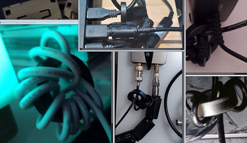
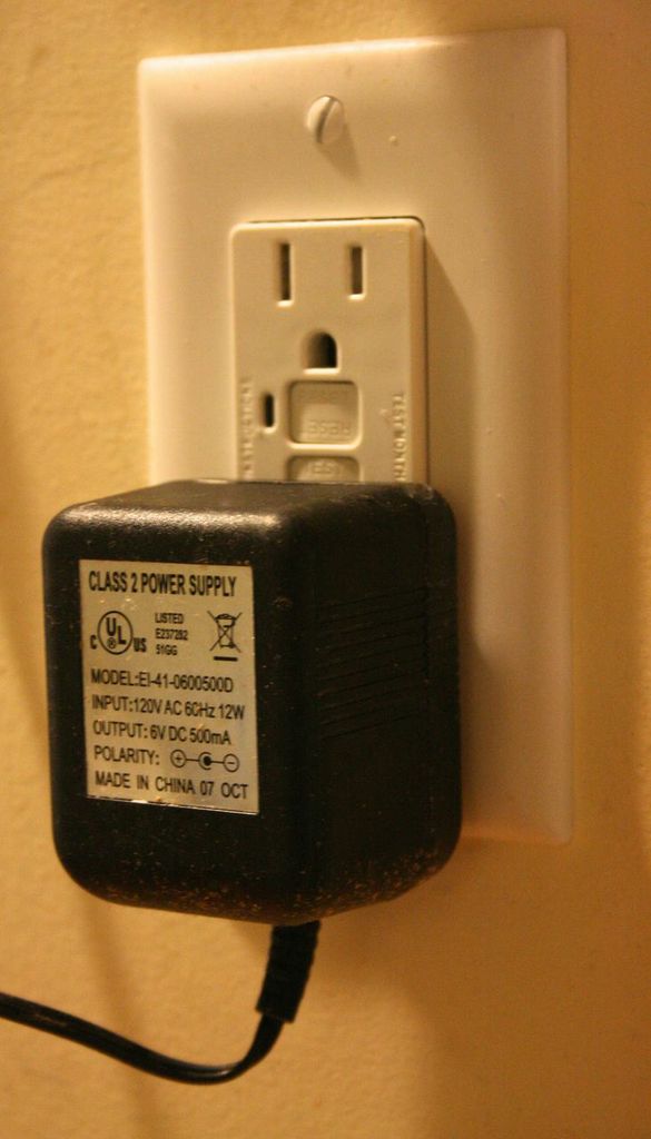
I then started to isolate which devices caused which kind of noise when listening to my outside amplified antennas for FM/VHF and UHF-TV transmissions. Many consumer Power adapters make a lot of noise from VLF up into UHF ranges. One thing I did right was to try a 10 pack of these little miracle “Wall Wart” toroids from Palomar Engineers. One by one, I put one of these small toroids (19mm inside diameter) on my home AC adapters as shown in the pictures, and the noises started disappearing. It does not explicitly say, but I believe it is Type 75 material which suppresses the noise generating AC adapter (at very low frequencies) when wrapped 8 – 12 times.
Most egregious of these was my CCrane FM2 transmitter. A strangled warbling sound kept emanating from the monitor closest to my laptop. Installing ferrites on the laptop and back of the monitor were not working. I moved the FM Transmitter and noticed a reduction in noise. So, I put one of these little toroids on the power input of the device and the noise disappeared. Apparently, it was picking up noise from the monitor (as well as its own power adapter) and rebroadcasting it to all my other radios! The strangled warbler is no more, I choked it (HaHa, sick bird joke).
While looking for the monitor noise, I put the eBay TDK ferrites on all the USB ports and HDMI ports. This has helped greatly on VHF and confirms my suspicion that these cheap TDK ferrites are indeed a common type of ferrite material. Some informative graphs can be seen in Jim Brown’s Audio paper mentioned before. One example might be Figure 22, which shows the #61 Series Resistance which peaks around 100 MHz when using a toroid with three “Turns”. More confused, I could not find a definition of a “Turn”. Eventually, in his longer paper to Amateur Radio operators, he defines it, “…is one more than the number of turns external to the cores”. Somewhere else he describes using many single snap-on ferrites being electrically equal to just one toroidal ferrite with multiple Turns. And interestingly, more Turns shifts the peak impedance substantially lower in frequency. So, using the graphs he supplies, one can target a noisy frequency range to try to suppress.
I then put 6 of the TDK ferrites on the VHF input to the AirSpy HF+. Some FM grunge was reduced and was thankful for that. The rest of the background noise truly seems to be coming from the outside picked up by the amplified antenna.
Also, I juggled a couple of the amplifiers around and now have separate VHF/FM and UHF/TV amplifiers which cleaned up the FM reception a little bit more – https://www.youtube.com/watch?v=zkDsy95et2w .
UHF TV Quality
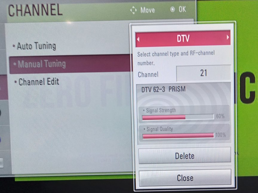
On a whim, I put the balance of the TDK ferrites on the FM/TV splitter input cable, 10 in all. The FM reception did not improve but the Over The Air UHF TV reception Quality improved noticeably. My weakest TV station now has a stable Signal level and the Quality is pegged at 100%. This is a nice surprise since it means that now all local TV stations on UHF will come in cleanly without dropouts and I can view all digital subchannels. I was even able to rescan and added two more low-power stations never seen before. ?
LED lights
I have common LED lights hanging over a number of fish tanks and some grow lights over an indoor plant box and can hear this noise on upper shortwave and higher radio bands. In a future article, I will explore RF noise from lights as its own special topic. For instance, why do some LED lights generate RFI and how to know before buying (I am using BR30 spot bulbs from name brands)? Also, there is a new kind of LED “filament” light out now that uses much smaller LED’s on both sides of an aluminum strip, greatly reducing electromagnetic noise output (or do they??). More questions than answers.
I will explore creating my own customized AC power cord attached to the AC power strips of the LED lights. I will need to test this for safety and efficacy, so I will want to take some time to do this right. The hope is that, using Jim’s info, I will be able to create a broad spectrum RFI suppression AC power cord and cost less than $30 each cord. We’ll see.
Finally, I will look at “stacked” toroids using different mixes of ferrite Types, creating a custom RF suppression better than using just one Type of ferrite material, using AC cords as the main examples. For instance, the best set of graphs in Jim’s paper, in my opinion, are Figures 21 and 24 compared to each other. Something I did not know before is that one can not only use multiple turns on a single toroid to get a lower, peaked frequency response, but also stack multiple toroids of the same Type to get a smoother frequency response. Then on top of this, combine that set with other Types to create a customized frequency response curve.
Radios are quieter now. Those pesky grow lights are still a problem as well as the upstairs neighbor’s lights which seem to be on a timer, making FM reception noisy again after 5pm!
These “Wall Wart” type adapters can create a lot of RFI
Many thanks to SWLing Post contributor, Jack Dully, who writes:
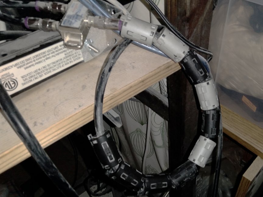
I was putting some things in my radio junk parts box and came across some chokes. So I tried a test with my Tecsun PL-880 on battery and the Tecsun supplied switching AC adapter, with and without chokes on the adapter.
WOW!
I tuned to a vacant station on battery power with headphones on. Then on AC power, the hash and static were incredible. Putting one large choke on the adapter power cord, wrapped about four times and it decreased considerably. So I attached a second choke and once again the static & hash decreased even more, almost to the point of sounding like I was running just on battery power.
Those chokes really do work well.
Thank you for sharing this, Jack. I almost never operate my portables while connected to a power supply, so I often forget about the importance of using a choke with inexpensive, lightweight radio power supplies. Thing is, so many things in our houses and shacks are powered by these QRM generators. In the shack, I’ve added chokes I’ve picked up at hamfests to a number of various power supplies. It does certainly help decrease the noise level. I’ve even used them on power cords for other appliances in the house that tend to spew RFI.
If you ever find a deal on chokes at a hamfest or electronics store, grab some. They can be an affordable solution for those noisy power supplies we still rely on.
Many thanks to SWLing Post contributor, Nick Booras, who writes:
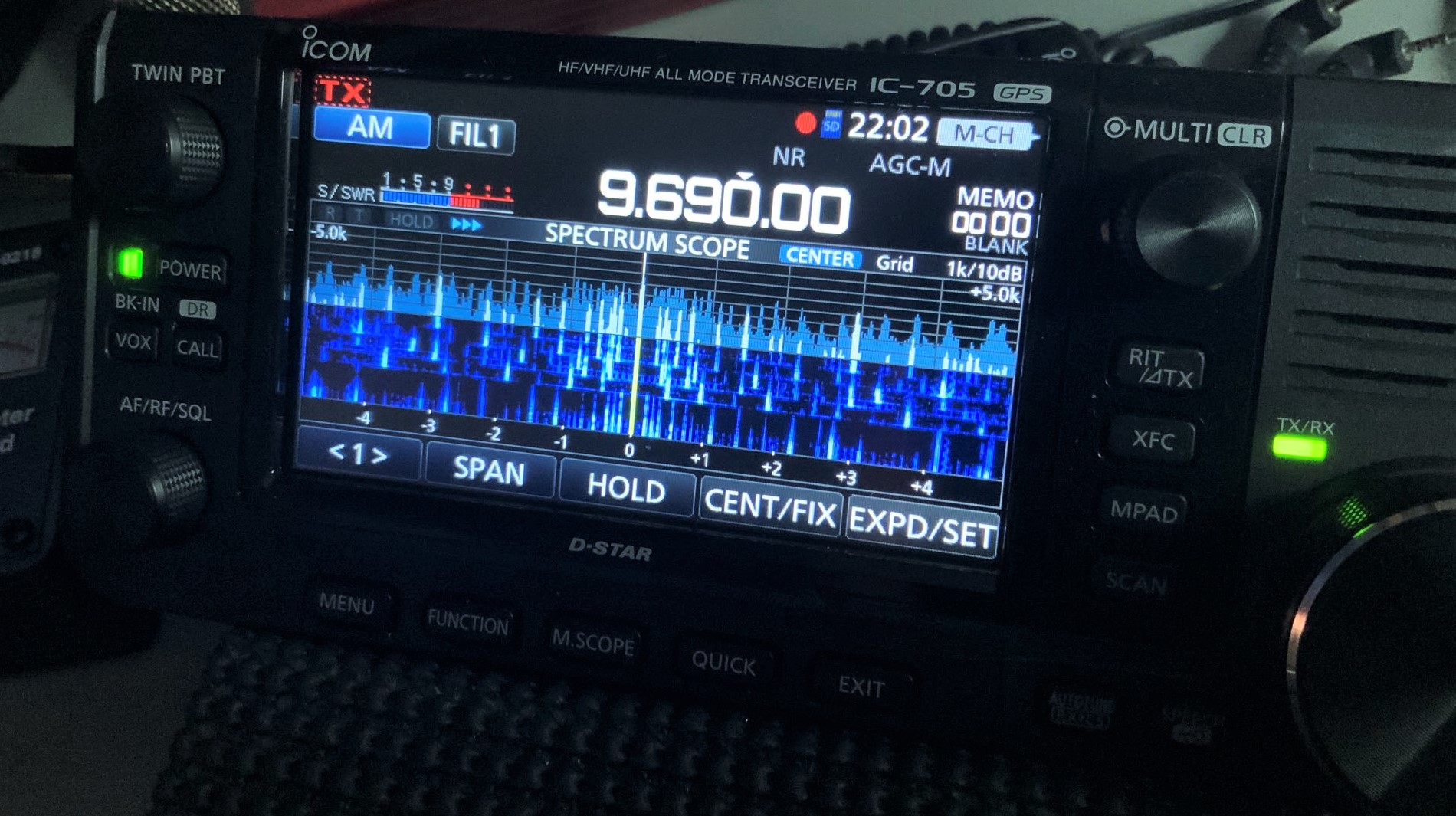
I am stuck in the house in Texas, bored and with no power. So I decided to make a couple videos with my phone. One nice thing about a power outage… no RFI [Radio Frequency Interference].
This Icom 705 is an awesome radio! Perhaps your viewers might like these.
Thank you for sharing these, Nick! Yes, as we’ve noted before, power outages are an ideal time to play radio and indulge in a low-noise environment! And I agree with you: the IC-705 is a superb shortwave broadcast receiver.
I hope our readers in Texas will have power restored soon–this has been a rough week for many.
Many thanks to SWLing Post contributor, TomL, who shares the following guest post:
Magnet Wire Vertical Loop Antenna
by TomL
For those of you in a noisy condo like me, the environment does not give me many options. I was experimenting with a YouLoop on the wooden porch with somewhat acceptable results. For its size, it is an excellent performer, especially on the lower bands. Here is a very interesting review of the YouLoop, including close-up pictures of the innards of the phase inverter and 1:1 balun, by John S. Huggins. However, it is not waterproof and I was concerned about the ice and snow ruining it. I could tape up the connectors with waterproof tape but I also wanted something with a bigger capture area. A magnet wire stealth antenna might be just the thing!
I just happened to have a waterproof 1:1 ATU balun from Balun Designs that I was going to use for future Amateur Radio use whenever I get around to passing the next level test; it is total overkill for what I intended to use it for. It would make a good connection point and (this one) also acts as an RF choke as well. One can make a 1:1 balun by buying the right Type of ferrite core and winding it yourself. Here is just one idea from Palomar Engineers.
So I dusted it off, went to a local store to get a 100 foot spool of 26 gauge magnet wire and tested it strung up around my living room. It came out to be a rectangle about 42 feet in circumference. Results were usable. I expected lots of noise and there is a great deal across the bands, so only the strongest shortwave stations were received. However, I was surprised by how strong the mediumwave band was and good to listen to without an amplifier.
I am ambivalent towards trying to perfectly match the impedance since this is a broadband receive-only antenna and the impedance will vary greatly over MW and SW bands. And I don’t want to mess with a remotely controlled tuned loop since this antenna was destined for the outdoor porch. I tried a Cross Country Wireless preselector at my desk but had some mixed results. I later found out, by disconnecting things in series, that the preselector inline raised the noise level about 5 dBm, so I took it out for now. Perhaps it needs more internal shielding or the connecting cable is bad.
Polarization is an issue, too. I have read that most man-made noise (QRM) is vertically polarized, so why would I use a vertically oriented loop? Then I saw David Casler’s video on loop antennas where he explains that connecting a vertical loop antenna at the bottom or the top makes it horizontally polarized (connecting the coax on the side makes it vertically polarized). I never knew that! Horizontal polarization will mitigate some of the offending QRM as well as match the polarization of mediumwave band transmitters. Furthermore, I read that a horizontal loop will have poor signal pickup at low frequencies because it is not high enough off the ground, similar to a horizontal dipole. For now, a vertical loop connected to facilitate horizontal polarization is what I want.
A note about wire size. People make a big deal about it but those are mostly amateur radio people. Transmission depends on efficiency so things like wire size, skin effect, standing waves, and other things matter (see here, for example). With a receive-only antenna it is OK to use very thin wire. Resonance can matter if you want the last ounce of signal strength with an antenna tuner, like in high-Q type loops where the bandwidth is very narrow and you are using a multi-turn loop with variable capacitor and a pick-up coil of wire to the receiver. Comparatively, my simple loop is depending more on a single turn of wire, the aperture size, length of wire for its performance, and carefully isolating the feedline coax using RF chokes at both ends.
Here is one example of a strong station from Cuba I was able to record because WLW was off the air for some unexpected reason.
Radio Reloj, Cuba 870 kHz (At the end, you can hear WLW come back online with CBS news):
Side note about Radio Reloj on Wikipedia, the strange format seems to fit well with a totalitarian regime, including a “corrector” who “corrects the content/writing errors to meet the requirements”. Read the wiki link for yourself. Not a society I want to live in, thank you very much!
Example of 80 meter band performance – Greetings to a new person from members of the “Awful, Awful, Ugly Net”, 3855 kHz:
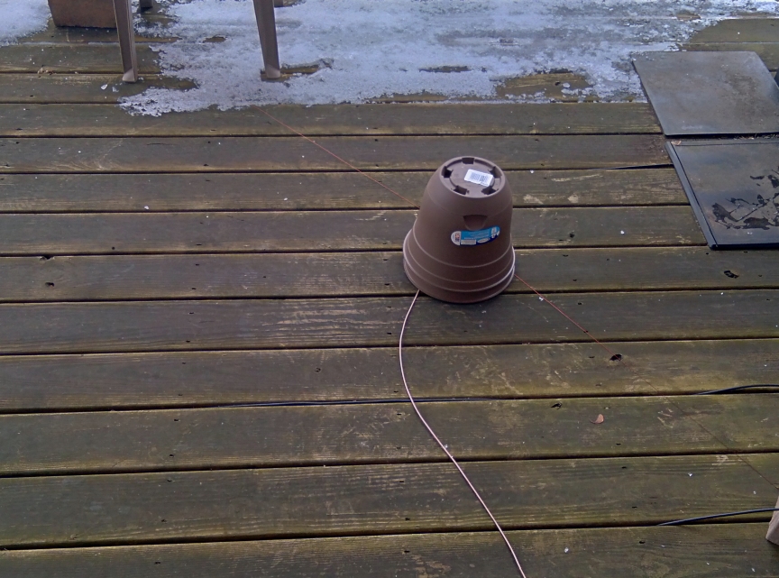
Encouraged by the results, I “installed” the magnet wire around the support beams of the wooden porch, wrapping it carefully to create a square loop. Holding it in place is a brick at each bottom corner since I am not allowed to nail anything into the Association-owned porch. The length came out to about 32 feet (8 feet per side), so I trimmed it and connected to the balun. I also added an RF choke at the Airspy HF+ input from Palomar Engineers which helped bring noise down a couple of S-units. That might not sound like a lot but by also shutting off the living room air filter and an AC switch with “wall-wart” AC power adapters on it, I was able to reduce the noise a little bit more. There is still a lot of noise from the neighbors, so it is not a perfect situation.
Here are two examples of reception with the outside installation.
Side note about the Radio Newsletter. I stumbled on it when using the YouLoop and found that some of the content is very interesting and informative. Of course it is geared mostly towards amateur radio but some of the news items are of general radio interest as well. It airs 1pm Saturday through 2am Sunday, USA Central Time. Obviously, many segments repeat during that lengthy timeframe and reception depends on propagation from Missouri.
KDDR 1220 kHz, West Fargo, ND station ID (presumably “nighttime” power of 327 watts):
The shortwave bands are still a noisy disaster but signal levels are higher compared to the YouLoop. Only the strongest stations come in like WRMI, WHRI, Radio Espana, Radio Habana, and CRI. And I can hear the loudest amateur radio operators.
Just for grins, here is Radio Rebelde on 5025 kHz when band conditions were above average:
Another phenomenon I am looking into is the reception pattern of a vertical loop. Less than 1/10th wavelength, the null is through the center of the loop. At one wavelength, the null manifests in the plane of the wire loop. They are too close to phase them but switching between two directional loop antennas might improve reception depending on frequency. We shall see in the future.
At least for now, I have a decent mediumwave band which performs better than the useful CCrane Twin-Ferrite amplified loop antenna that was used in the (noisy) indoors, I can hear the 160 & 80 meter amateur bands better, and the reception of the strongest shortwave broadcasters are more predictable. Not bad for four dollars of wire!
Brilliant, Tom! Again, I love how you’ve not only made an inexpensive antenna, but you’ve even done it within your HOA regulations. You’re right, too: if you’re not transmitting into an antenna, it blows the experimentation door wide open! Thank you once again for sharing your project with us.
Many thanks to SWLing Post contributor, 13dka, who shares the following guest post:
Gone fishing…for DX: Reception enhancement at the seaside
by 13dka
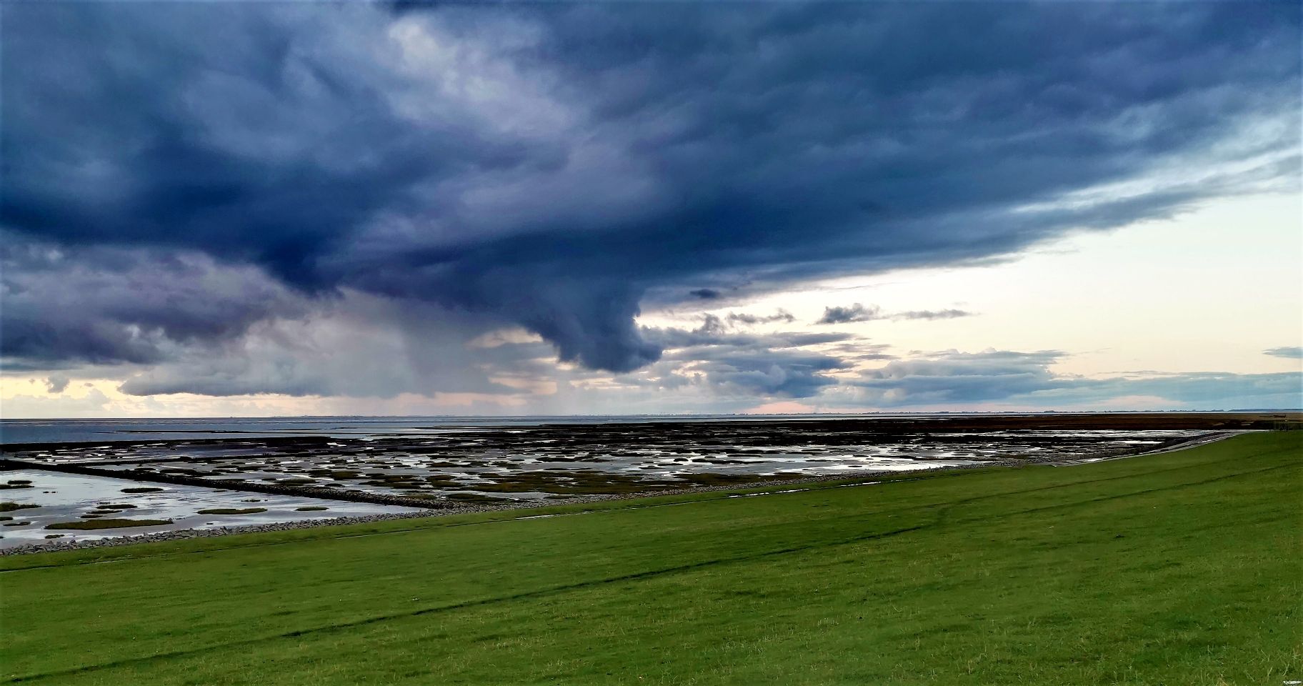
In each of my few reviews I referred to “the dike” or “my happy place”, which is a tiny stretch of the 380 miles of dike protecting Germany’s North Sea coast. This is the place where I like to go for maximum listening pleasure and of course for testing radios. Everyone knows that close proximity to an ocean is good for radio reception…but why is that? Is there a way to quantify “good”?
Of course there is, this has been documented before, there is probably lots of literature about it and old papers like this one (click here to download PDF). A complete answer to the question has at least two parts:
1. Less QRM
It may be obvious, but civilization and therefore QRM sources at such a place extend to one hemisphere only, because the other one is covered with ocean for 100s, if not 1000s of miles. There are few places on the planet that offer such a lack of civilization in such a big area, while still being accessible, habitable and in range for pizza delivery. Unless you’re in the midst of a noisy tourist trap town, QRM will be low. Still, you may have to find a good spot away from all tourist attractions and industry for absolutely minimal QRM.
My dike listening post is far enough from the next small tourist trap town (in which I live) and also sufficiently far away from the few houses of the next tiny village and it’s located in an area that doesn’t have HV power lines (important for MW and LW reception!) or industrial areas, other small villages are miles away and miles apart, the next town is 20 km/12 miles away from there. In other words, man-made noise is just not an issue there.
That alone would be making shortwave reception as good as it gets and it gives me an opportunity to check out radios on my own terms: The only way to assess a radio’s properties and qualities without or beyond test equipment is under ideal conditions, particularly for everything that has to do with sensitivity. It’s already difficult without QRM (because natural noise (QRN) can easily be higher than the receiver’s sensitivity threshold too, depending on a number of factors), and even small amounts of QRM on top make that assessment increasingly impossible. This is particularly true for portables, which often can’t be fully isolated from local noise sources for a couple of reasons.
Yes, most modern radios are all very sensitive and equal to the degree that it doesn’t make a difference in 98% of all regular reception scenarios but my experience at the dike is that there are still differences, and the difference between my least sensitive and my most sensitive portable is not at all negligible, even more because they are not only receivers but the entire receiving system including the antenna. You won’t notice that difference in the middle of a city, but you may notice it in the woods.
When the radio gets boring, I can still have fun with the swing and the slide!
2. More signal
I always had a feeling that signals actually increase at the dike and that made me curious enough to actually test this by having a receiver tuned to some station in the car, then driving away from the dike and back. Until recently it didn’t come to me to document or even quantify this difference though. When I was once again googling for simple answers to the question what the reason might be, I stumbled upon this video: Callum (M0MCX) demonstrating the true reason for this in MMANA (an antenna modeling software) on his “DX Commander” channel:
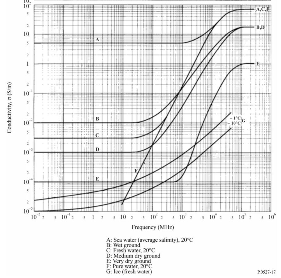
To summarize this, Callum explains how a pretty dramatic difference in ground conductivity near the sea (click here to download PDF) leads to an increase in antenna gain, or more precisely a decrease in ground return losses equaling more antenna gain. Of course I assumed that the salt water has something to do with but I had no idea how much: For example, average ground has a conductivity of 0.005 Siemens per meter, salt water is averaging at 5.0 S/m, that’s a factor of 1,000 (!) and that leads to roughly 10dB of gain. That’s right, whatever antenna you use at home in the backcountry would get a free 10dB gain increase by the sea, antennas with actual dBd or dBi gain have even more gain there.
That this has a nice impact on your transmitting signal should be obvious if you’re a ham, if not just imagine that you’d need a 10x more powerful amplifier or an array of wires or verticals or a full-size Yagi to get that kind of gain by directionality. But this is also great for reception: You may argue that 10dB is “only” little more than 1.5 S-units but 1.5 S-units at the bottom of the meter scale spans the entire range between “can’t hear a thing” and “fully copy”!
A practical test
It’s not that I don’t believe DX Commander’s assessment there but I just had to see it myself and find a way to share that with you. A difficulty was finding a station that has A) a stable signal but is B) not really local, C) on shortwave, D) always on air and E) propagation must be across water or at least along the coastline.
The army (or navy) to the rescue! After several days of observing STANAG stations for their variation in signal on different times of the day, I picked one on 4083 kHz (thanks to whoever pays taxes to keep that thing blasting the band day and night!). I don’t know where exactly (my KiwiSDR-assisted guess is the English channel region) that station is, but it’s always in the same narrow range of levels around S9 here at home, there’s usually the same little QSB on the signal, and the signals are the same day or night.
On top of that, I had a look at geological maps of my part of the country to find out how far I should drive into the backcountry to find conditions that are really different from the coast. Where I live, former sea ground and marsh land is forming a pretty wide strip of moist, fertile soil with above average conductivity, but approximately 20km/12mi to the east the ground changes to a composition typical for the terminal moraine inland formed in the ice age. So I picked a quiet place 25km east of my QTH to measure the level of that STANAG station and also to record the BBC on 198 kHz. Some source stated that the coastal enhancement effect can be observed within 10 lambda distance to the shoreline, that would be 730m for the 4 MHz STANAG station and 15km for the BBC, so 25km should suffice to rule out any residue enhancement from the seaside.
My car stereo has no S-meter (or a proper antenna, so reception is needlessly bad but this is good in this case) so all you get is the difference in audio. The car had the same orientation (nose pointing to the east) at both places. For the 4 MHz signal though (coincidence or not), the meter shows ~10dBm (or dBµV/EMF) more signal at the dike.
3. Effect on SNR
Remember, more signal alone does not equal better reception, what we’re looking for is a better signal-to-noise ratio (SNR). Now that we’ve established that the man-made noise should be as low as possible at “my” dike, the remaining question is: Does this signal enhancement have an effect on SNR as well? I mean, even if there is virtually no local QRM at my “happy place” – there is still natural noise (QRN) and wouldn’t that likely gain 10dB too?
Here are some hypotheses that may be subject of debate and some calculations way over my head (physics/math fans, please comment and help someone out who always got an F in math!). Sorry for all the gross oversimplifications:
Extremely lossy antennas
We know that pure reception antennas are often a bit different in that the general reciprocity rule has comparatively little meaning, many antennas designed for optimizing reception in specific situations would be terrible transmitting antennas. One quite extreme example, not meant to optimize anything but portability is the telescopic whip on shortwaves >10m. At the dike, those gain more signal too. When the QRN drops after sunset on higher frequencies, the extremely lossy whip might be an exception because the signal coming out of it is so small that it’s much closer to the receiver noise, so this friendly signal boost could lift very faint signals above the receiver noise more than the QRN, which in turn could mean a little increase in SNR, and as we know even a little increase in SNR can go a long way.
The BBC Radio 4 longwave recording is likely another example for this – the unusually weak signal is coming from a small and badly matched rubber antenna with abysmal performance on all frequency ranges including LW. The SNR is obviously increasing at the dike because the signal gets lifted more above the base noise of the receiving system, while the atmospheric noise component is likely still far below that threshold. Many deliberately lossy antenna design, such as flag/tennant, passive small aperture loops (like e.g. the YouLoop) or loop-on-ground antennas may benefit most from losses decreasing by 10dB.
Not so lossy antennas, polarization and elevation patterns
However, there is still more than a signal strength difference between “big” antennas and the whips at the dike: Not only at the sea, directionality will have an impact on QRN levels, a bidirectional antenna may already decrease QRN and hence increase SNR further, an unidirectional antenna even more, that’s one reason why proper Beverage antennas for example work wonders particularly on noisy low frequencies at night (but this is actually a bad example because Beverage antennas are said to work best on lossy ground).
Also, directional or not, the “ideal” ground will likely change the radiation pattern, namely the elevation angles, putting the “focus” of the antenna from near to far – or vice versa: As far as my research went, antennas with horizontal polarization are not ideal in this regard as they benefit much less from the “mirror effect” and a relatively low antenna height may be more disadvantageous for DX (but maybe good for NVIS/local ragchewing) than usual. Well, that explains why I never got particularly good results with horizontal dipoles at the dike!
Using a loop-on-ground antenna at a place without QRM may sound ridiculously out of place at first, but they are bidirectional and vertically polarized antennas, so the high ground conductivity theoretically flattens the take-off angle of the lobes, on top of that they are ~10dB less lossy at the dike, making even a LoG act more like something you’d string up as high as possible elsewhere. They are incredibly convenient, particularly on beaches where natural antenna supports may be non-existent and I found them working extremely well at the dike, now I think I know why. In particular the preamplified version I tried proved to be good enough to receive 4 continents on 20m and a 5th one on 40m – over the course of 4 hours on an evening when conditions were at best slightly above average. Though the really important point is that it increased the SNR further, despite the QRN still showing up on the little Belka’s meter when I connected the whip for comparison (alas not shown in the video).
The 5th continent is missing in this video because the signals from South Africa were not great anymore that late in the evening, but a recording exists.
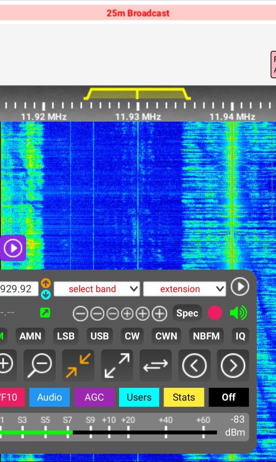
Here’s a video I shot last year, comparing the same LoG with the whip on my Tecsun S-8800 on 25m (Radio Marti 11930 kHz):
At the same time, I recorded the station with the next decent (but more inland) KiwiSDR in my area:
Of course, these directionality vs noise mechanisms are basically the same on any soil. But compensating ground losses and getting flat elevation patterns may require great efforts, like extensive radial systems, buried meshes etc. and it’s pretty hard to cover enough area around the antenna (minimum 1/2 wavelength, ideally more!) to get optimum results on disadvantaged soils, while still never reaching the beach conditions. You may have to invest a lot of labor and/or money to overcome such geological hardships, while the beach gives you all that for free.
But there may be yet another contributing factor: The gain pattern is likely not symmetrical – signals (and QRN) coming from the land side will likely not benefit the same way from the enhancement, which tapers off quickly (10 wavelengths) on the land side of the dike and regular “cross-country” conditions take place in that direction, while salt water stretching far beyond the horizon is enhancing reception to the other side.
So my preliminary answer to that question would be: “Yes, under circumstances the shoreline signal increase and ground properties can improve SNR further, that improvement can be harvested easily with vertically polarized antennas”.
Would it be worthwhile driving 1000 miles to the next ocean beach… for SWLing?
Maybe not every week–? Seriously, it depends.
Sure, an ocean shoreline will generally help turning up the very best your radios and antennas can deliver, I think the only way to top this would be adding a sensible amount of elevation, a.k.a. cliff coasts.
If you’re interested in extreme DX or just in the technical performance aspect, if you want to experience what your stuff is capable of or if you don’t want to put a lot of effort into setting up antennas, you should definitely find a quiet place at the ocean, particularly if your options to get maximum performance are rather limited (space constraints, QRM, HOA restrictions, you name it) at home.
If you’re a BCL/program listener and more interested in the “content” than the way it came to you, if you’re generally happy with reception of your favorite programs or if you simply have some very well working setup at home, there’s likely not much the beach could offer you in terms of radio. But the seaside has much more to offer than fatter shortwaves of course.
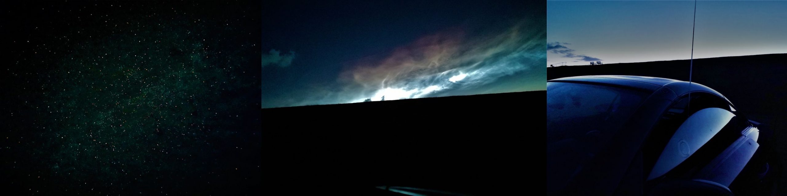
From left to right: Starry sky capture with cellphone cam, nocticlucent clouds behind the dike, car with hot coffee inside and a shortwave portable suction-cupped to the side window – nights at the dike are usually cold but sometimes just beautiful. (Click to enlarge.)
However, getting away from the QRM means everything for a better SNR and best reception. In other words, if the next ocean is really a hassle to reach, it may be a better idea to just find a very quiet place nearby and maybe putting up some more substantial antenna than driving 1000 miles. But if you happen to plan on some seaside vacation, make absolutely sure you bring two radios (because it may break your heart if your only radio fails)!
A little update (2023):
Like I said, the +10dB signal boost works both ways and here’s a nice example that I thought should be here. This is W4SWV, literally standing with both feet in the Atlantic ocean at the South Carolina coastline, carrying a 25W backpack radio with a whip and talking to F6ARC in France on 17m – received at my side of the pond using my simple vertical 33’/10m monopole antenna at the dike:
This was recorded on July 4th, 2021 and does not provide a reference to demonstrate how good or bad this is of course, all you have is my word that getting such a solid and loud signal from a 25W station on the US East Coast was just outstanding (compared to a fair number of coastal QRP stations I copied at the dike over the years, or the average 100W inland stations).
Meanwhile I found out that I’m luckily not the only (or the first) person who tried to make some practical experiments to reassess the theories in recent times: Greg Lane (N4KGL) made measurements by transmitting a WSPR signal simultaneously off 2 locations, one near the shoreline and one more inland. Measuring the signals created in distant WSPR receivers, he got similar results. He made a presentation about it in 2020:
Many thanks to SWling Post contributor, Emilio Ruiz, who shares the following guest post:
Apprehending an RFI-generating monster!
At the beginning of the year, I was sad because, at home, an awful RFI noise appeared. The next few months the noise increase until S9!!. Day and night my receivers and my feelings were so dampened with this terrific RFI–only the lower Broadcast Band (900 to 540 Khz) was relatively immune to it.
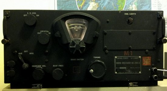
Yesterday, we had a storm and the mains electricity service went off, so I connect a 12 volt battery to my RT-749b military surplus transceiver and the received signals were very clean like the “good old days”.
(Above: Listen W1AW loong distant from my QTH in Chiapas Mexico).
When the power electricity come back on, so did the RFI too!!
(Above: W1AW gone)
Remembering the recently publish post in SWLing Post about RFI, I did some testing by
cutting the electricity to my home (the main switch) and the RFI was gone!! So I discovered the RFI lives in my house–not in the outside wires!!
I put batteries in my old shortwave portable radio and searched (like Ghostbusters) all outlets contacts, one by one, connect and disconnected each device.
And I found the guilty party!
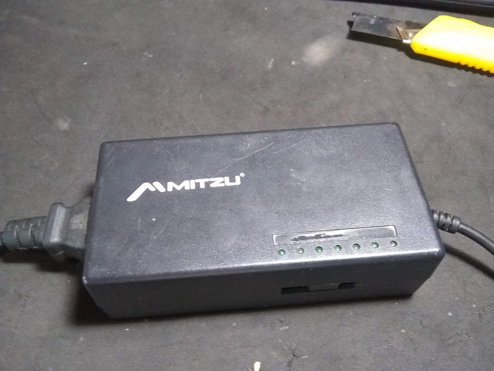
Exhibit A: The Mitzu laptop power supply
On December 2019, the power supply of my son’s laptop broke, so I bought a cheap substitute.
The RFI produced by this little monster could be heard at a distance of about 200 meters from my QTH!!! (Much like an old transmitter spark gap–!)
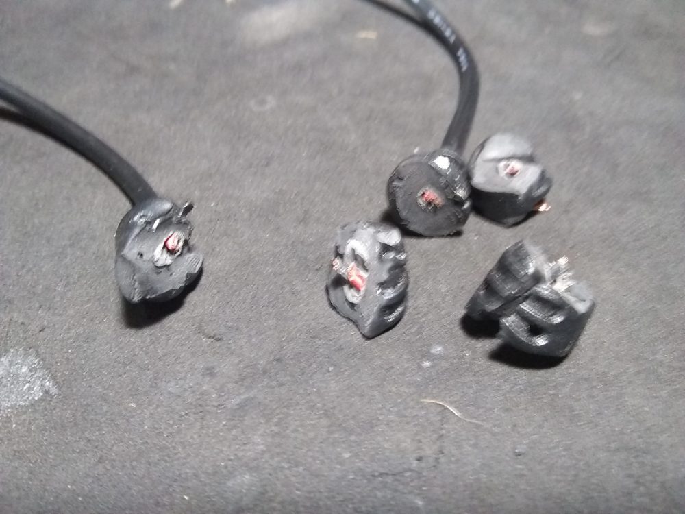
Even this cheap power supply apparently featured ferrite toroids on the wire but turns out it is fake!! It was only a plastic ball!
Exhibit B: Fake toroids!
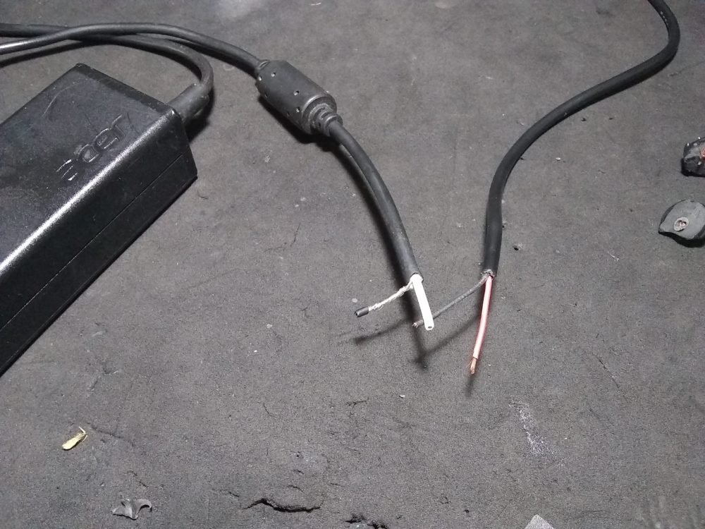
The wires were also not shielded. No doubt one of the worst switched-mode power supplies I could have purchased.
Exhibit C: The Mitzu RFI generator wire without shield, only pair wires!
I found a old Acer power supply with same specs and I replaced out the RFI monster one.
And now? The shortwave bands are clean again.
(Video: Testing my Kenwood R-600 rx with Radio Exterior de España… plugging and unplug the Mitzu monster RFI generator).
So I wanted to share what happened to me, so perhaps it can be useful for other SWLing Post blog friends.
Watch these little switched mode power supplies from all devices in your home. Replace them if you detect RFI levels that harms SWLing. Consider disconnect all devices (vampire consumption–or phantom loads) if not in use; the radio waves and electric bill will be grateful to you!
WOW! What a difference! Emilio, that was great investigative work on your part. It’s as if that switching power supply was specifically designed to create RFI! No shield and fake toroids? That’s just criminal in my world!
Thank you so much for sharing your story. Hopefully, this might encourage others to investigate and apprehend their own local RFI monsters!
(And by the way, Emilio, I love that RT-749b military transceiver!)