Shortwave listening and everything radio including reviews, broadcasting, ham radio, field operation, DXing, maker kits, travel, emergency gear, events, and more
I just finished listening to the most recent episode of the Ham Radio Workbench with John Fallows (VE6EY) as a guest.
John is an SWL and Ham Radio operator and speaks at length about how he uses diversity reception to mitigate persistent local RFI (radio frequency interference).
If you have persistent issues with radio interference or if you’ve been curious about using diversity reception for mediumwave and shortwave DXing, I highly recommend listening to this episode. John has been known to frequent the SWLing Post and actually comes into the discussion primarily from an SWL’s perspective.
If you’ve tried diversity reception or a noise-cancelling system like the Timewave ANC-4+ in the past with mixed results, you’ll definitely benefit from listening to John’s best practices.
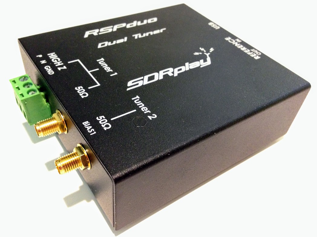
In addition, John points out that the excellent SDRplay RSPduo is a very affordable way to explore proper diversity reception.
How effectively can you mitigate RFI with diversity reception? Check out this video on YouTube queued up to the point where John does a live demo with his Anan SDR and loop antennas: https://youtu.be/vu8D87aVUTQ?t=2011 (I also recommend watching to full video presentation for even more detail.)
I’ve embedded the audio for the Ham Radio Workbench podcast below, but you can also find it along with show notes on the Ham Radio Workbench website.
Ham Radio Workbench is one of my favorite podcasts; if you like exploring a wide variety of technical topics, I highly recommend checking it out. It’s available on all podcasting platforms.
Radio Waves: Stories Making Waves in the World of Radio
Because I keep my ear to the waves, as well as receive many tips from others who do the same, I find myself privy to radio-related stories that might interest SWLing Post readers. To that end: Welcome to the SWLing Post’sRadio Waves, a collection of links to interesting stories making waves in the world of radio. Enjoy!
Radio facsimile technology never fully caught on, but what if it had?
In the beginning, there were newspapers.
And then radio arrived, challenging the newspapers’ journalistic monopoly.
At first, many newspapers fought the new competitor, refusing to print radio news or program schedules. But some went in the opposite direction, deciding to operate their own radio stations to augment their businesses. And finally, a few brave pioneering publications went even farther: They tried to deliver their newspapers via radio facsimile.
In the early 1930s, radio facsimile looked like the dream application for newspapers. They could use their own local radio stations to deliver newspapers directly to consumers during overnight hours. It would eliminate the cost of printing and distribution and shift those costs onto consumers, who would provide their own printers and paper.
This led several radio stations and newspapers to experiment with facsimile transmission during the late 1930s.
THE FINCH SYSTEM
The person most responsible for this technology was William G. H. Finch. He worked for the International News Service and set up their first teletype circuits between New York, Chicago and Havana. He became interested in facsimile machines and eventually amassed hundreds of patents. [Continue reading the full article…]
Why Chicago Public Media and the Chicago Sun-Times are exploring a merger
The Chicago Sun-Times needs help. After being bought and sold several times over the last decade, the 73-year-old paper is looking for a more stable home to continue its award-winning reporting — and it may have finally found it in an unexpected place: a radio station.
Chicago Public Media, which owns the radio station WBEZ, is currently in talks with the Sun-Times to merge. A final deal would combine their newsrooms and audiences in hopes of creating a financially stable enterprise for both teams. Similar mergers and acquisitions have become a common way to bolster the struggling print industry, but if radio were to take on a major newspaper, that would be a first.
“Audio is a growth business,” says Jim Friedlich, chief executive of The Lenfest Institute for Journalism, who advised CPM on the potential merger. “Now Chicago Public Media and other media with audio roots have both the wherewithal and the self-confidence to take a bold step like this.”
Since 2004, US newspapers have shut down at a rate of 100 per year, a pace that’s only accelerated since the start of the pandemic. To stay afloat, some smaller newsrooms have given up independence, being bought by news conglomerates or becoming joint entities with other local outlets — and public radio and TV stations have increasingly offered themselves up as partners. New York Public Radio acquiring the website Gothamist was one of nine similar deals in recent years, triggering researchers to document the trend by creating the Public Media Mergers Project. Public radio has been a particularly strong force, holding its ground amid digitization and the podcasting craze (partially because it’s participated in it), and it might be strong enough to help print do the same thing. [Continue reading…]
In the 125 years since Marconi made his first radio transmissions, the spectrum has been divvied up into ranges and bands, most of which are reserved for governments and large telecom companies. Amidst all of the corporate greed, the ‘little guys managed to carve out their own small corner of the spectrum, with the help of organizations like the American Radio Relay League (ARRL).
Since 1914, the ARRL has represented the interests of us amateur radio enthusiasts and helped to protect the bands set aside for amateur use. To actually take advantage of the wonderful opportunity to transmit on these bands, you need a license, issued by the FCC. The licenses really aren’t hard to get, and you should get one, but what if you don’t feel like taking a test? Or if you’re just too impatient?
Well, fear not because there’s some space on the radio spectrum for you, too.
Welcome to the wonderful world of (legal!) unlicensed radio experimentation, where anything goes. Okay, not anything but the possibilities are wide open. There are a few experimental radio bands, known as LowFER, MedFER, and HiFER where anyone is welcome to play around. And of the three, LowFER seems the most promising.
LowFER, as the name would suggest, contains the lowest frequency range of the three, falling between 160 kHz and 190 kHz, with a whopping wavelength of around one mile. Also known as the 1750-meter band, this frequency range is well-suited for long transmission paths through ground wave propagation, a mode in which the radio signals move across the surface of the earth. This can easily carry even low-power signals hundreds of miles, and occasionally through some atmospheric black magic, signals have been known to travel thousands of miles. These ground wave signals also travel well across bodies of water, especially salt water.
We regret to inform our listeners that our colleague Juan Antonio “Tony” Middleton passed away in Buenos Aires due to health complications, at the age of 82. His distinctive British accent is part of the history of RAE, where he hosted the English-language program for almost three decades. English-speaking listeners around the world remember his warmth and clarity on the air, not to mention his classic opening line: “This is the international service of the Argentine Radio”.
Born in Argentina and son of British immigrants, he ventured into acting in the English language with the group “Suburban Players”, while he was engaged in various commercial activities with his family. In 1981 he had the opportunity to join RAE as a substitute, thanks to his impeccable English and his pleasant voice. In 1983 he joined as a regular and went on to become head of the English-language department at the station, until his retirement in 2008. [Continue reading…]
Mlburn Garland “Gil” Butler was born December 1, 1935 in Bradenton, Florida. He attended local schools, where his mother was a teacher. He grew up in a community where electrification was still being developed, where the Saturday morning movies were an all-day entertainment for kids, and where families would gather in the town square on Sundays for band music and ice cream. After a brief stint in the Army (serving as a quartermaster at a base near Washington, D.C.), Gil Butler went to college in Colorado, returning to Florida where he graduated from the University of Florida with a degree in radio engineering. Along the way, he met and after a whirlwind courtship married Judith Bunten, who would become his lifelong companion. Gil Butler began working as a DJ at a small radio station in Bradenton, Florida in the early 1950s, spinning disks from the very beginning of Rock and Roll. His love of music of all sorts, from Jazz to Rock to Classical, his collection evolved through several formats (LP, cassette, CD, and MPs), and his special chair was always surrounded by the music he would enjoy while reading in the evening. Professionally, Gil moved up to larger stations and more challenging positions in radio and television; working for radio stations around the Tampa Bay area. His first TV gig was as a general reporter for WTVT in Tampa. From there, he moved to WXYZ in Detroit, Michigan, before moving to Silver Spring in the Washington D.C. where he worked as a White House Correspondent for local CBS affiliate, WTOP, covering Washington politics under presidents Nixon and Ford. During this period, Gil appears briefly in Timothy Crouse’s The Boys on the Bus (a recounting of the White House Press Corps during the Nixon Era). He was one of the six “Knights of the Green Ottoman,” named for an item of furniture in the 1972 White House press complex, where the newsmen would gather and share notes. In one passage, he is described: “Gil Butler… the reporter for TV station WTOP, who was chuckling over a volume of Mencken…” This description will surprise no one who knew him, as Gil was a voracious reader. He was always in the middle of a massive nonfiction volume about politics, military history or the Space Race. After WTOP, in 1978, Gil began his ultimate career at the Voice of America, the United States Information Agency’s international radio network. Over a nearly three decade career with Voice of America, he covered 68 countries, working abroad in Cairo, Egypt, Beiruit Lebanon, Beijing, China, London, England, as well as covering the State Department and Pentagon during his time at home between foreign assignments. At the Voice of America’s 40th Anniversary Celebration, Gil received the Meritorious Honor Award for his work in Cairo covering the assassination and funeral of Egyptian President Sadat and its aftermath. Twenty-seven years later, Voice of America News ran a story looking back at that work and the restraint and integrity he exercised in waiting for confirmation before reporting that Sadat had been killed. [Continue reading…]
Radio Waves: Stories Making Waves in the World of Radio
Because I keep my ear to the waves, as well as receive many tips from others who do the same, I find myself privy to radio-related stories that might interest SWLing Post readers. To that end: Welcome to the SWLing Post’sRadio Waves, a collection of links to interesting stories making waves in the world of radio. Enjoy!
Many thanks to SWLing Post contributors David Iurescia, Ronnie Smith, Troy Riedel, Jack Dully, and the Southgate ARC for the following tips:
Radio Prague asks, “Would you like to be featured on our broadcast?” (Radio Prague via Facebook)
Our 85th anniversary is coming up on August 31st! We’re celebrating the occasion with a special broadcast that day and would love to hear from you – our listeners. If you’d like to send us your greetings, please record a message and send an audio file via email (to [email protected]) or Facebook. Due to time constraints, your recording should be around 30 seconds long. Please include your first name, where you live, how long you’ve been listening, and what you like most about Radio Prague Int’l.
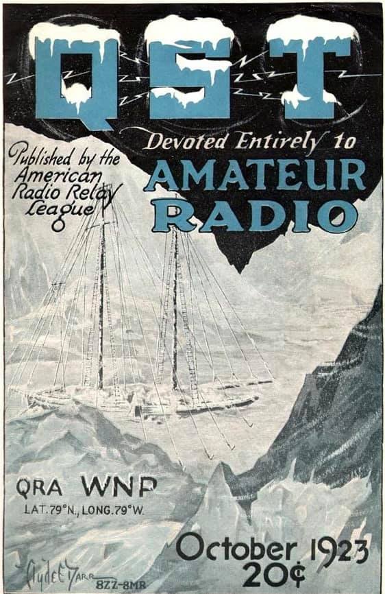
The schooner Bowdoin is a century old this year. Now owned by the Maine Maritime Academy (MMA) as a training vessel, the ham radio history of the 88-foot (LOA) Bowdoin is often neglected. Constructed in Maine specifically for Arctic exploration, the vessel relied on amateur radio for communication during explorer Donald B. MacMillan’s Arctic Expedition of 1923 and on the MacMillan-McDonald-Byrd Expedition of 1925 — thanks in part to ARRL co-founder Hiram Percy Maxim, W1AW. The venerable vessel, the official vessel of the State of Maine and the flagship of Maine Maritime Academy’s Vessel Operations and Technology Program, recently underwent a complete hull restoration and refitting and has done a little touring to mark its centenary. Its home port is Castine, Maine.
The longwave transmitters MacMillan used on his earlier missions had proved “unable to penetrate the screen of the aurora borealis,” then-ARRL historian Michael Marinaro, WN1M (SK), explained in his article, “Polar Exploration,” from the June 2014 issue of QST. In 1923, MacMillan turned to ARRL for help in outfitting his next expedition with better wireless gear. Marinaro recounted, “It was enthusiastically provided.” Maxim and the ARRL Board recruited Donald H. Mix, 1TS, of Bristol, Connecticut, to accompany the crew as its radio operator.
M.B. West, an ARRL Board member, designed the gear, which was then built by amateurs at his firm, Zenith Electronics. The transmitter operated on the medium-wave bands of 185, 220, and 300 meters, running 100 W to a pair of Western Electric “G” tubes. Earlier exploratory missions had used gear that operated on longwave frequencies. The shipboard station on board the Bowdoin was given the call sign WNP — Wireless North Pole. [Continue reading…]
In 1893, sending information across America is a time-consuming process. Letters travel slowly by land, and those who can afford it, send telegrams along a limited network of fixed wires. But two rival inventors have the same idea for improving things: wireless communication. Nikola Tesla is one of the most famous and successful thinkers of his day, single-handedly changing the way electricity is supplied and generated. Guglielmo Marconi is a young, uneducated Italian inventor who ignores scientific consensus and goes with his gut. Both want to rid the world of wires and send messages through the air. With millions of dollars on the line, the two men battle to dominate the new market and bring radio to the masses. [Click here to view episode on the History Channel.]
MARION COUNTY, Fla. — A Marion County woman is taking on her neighborhood association, in a matter she said puts her health at risk.
Michelle Smith, a Type 1 Diabetic, and a consultant determined that her neighbor’s ham radio hobby might have interfered with the doses of insulin being pushed out from her pump.
The 55+ community where she lives hired that consultant and told the neighbor to shut down his amateur radio station.
But a copy of the community’s rules shows a change was put in place that could pave the way for other similar antennas to be installed.
9 Investigates learned that Smith’s complaint went all the way to the state level.
She wants the Florida Commission on Human Relations to make a determination whether the community’s board and management is doing enough to protect her and others with medical devices.[…]
RTE carried out essential maintenance of the Long Wave transmitter in Clarkstown, Co. Meath for two months during which period RTE Radio 1 was not available on 252 kHz.
This essential maintenance of the transmitter was due to be carried out in 2020, but was postponed due to Covid-19 restrictions. For the health and safety of those carrying out the works, the transmitter had to be switched off for the works period. Any overhaul has to be completed during the summer months when there is good light and weather conditions.
Transmissions commenced once again last Monday with an output of 500 kiloWatt during daytime and 100 kiloWatt at nighttime.
During this shutdown, one could receive Radio Algeria transmitting on the same frequency with 1.5 megaWatt during the day and 750 kiloWatt at night, broadcasting a varied program.
Radio Waves: Stories Making Waves in the World of Radio
Because I keep my ear to the waves, as well as receive many tips from others who do the same, I find myself privy to radio-related stories that might interest SWLing Post readers. To that end: Welcome to the SWLing Post’sRadio Waves, a collection of links to interesting stories making waves in the world of radio. Enjoy!
Many thanks to SWLing Post contributors Ron, Rich Cuff, and the Southgate ARC for the following tips:
Vintage home movie film provided by New Jersey radio amateur Bob Schenck, N2OO, was the highlight of a PBS documentary about the Hindenburg disaster. The film, shot by his uncle Harold Schenck, may provide clues as to what initiated the disastrous 1937 fire that destroyed the airship Hindenburg and claimed 35 lives as the German zeppelin was landing at Lakehurst, New Jersey. Harold Schenck tried to interest government investigators in his film, shot from a different angle than newsreel footage that begins only after the fire was well under way, but it was largely overlooked. “Nobody ever asked for it,” Bob Schenck explains in the documentary.
The Schenck film is the highlight of a PBS “NOVA” documentary, Hindenburg: The New Evidence, that investigates the issue in considerable depth in an effort to unlock the secrets of the cold case. The program aired on May 19 and remains available for streaming.
“My dad had bought this nifty Kodak camera — a wind-up movie camera, 8 millimeters — and he couldn’t come [to the Hindenburg landing] because he worked,” Bob Schenck recounted during the documentary. “So, he asked my uncle and my mom if they would take some shots and see the Hindenburg land.”
Bob Schenck approached Dan Grossman, an expert on airships, including Hindenburg, in 2012 during a commemoration of the disaster that forever memorialized radio reporter Herbert Morrison’s plaintive on-air reaction, “Oh, the humanity!” The NOVA documentary not only shares Schenck’s footage, which provided new clues to re-examine the cause of the explosion. The documentary also reviews scientific experiments that helped investigators come to a fresh understanding of what set off the fire. [Continue reading…]
Glenn O’Donnell K3PP of Forrester Research notes the chip shortage may have a more serious impact than first thought and gives Amateur Radio rigs as an example of what might be affected
Self-described as a “ham radio nut,” O’Donnell discussed one of his hobbies to explain how the sway of tech titans could impact smaller companies as industries compete for limited resources.
“In this hobby, the newer radio “toys” are advanced technology, but the hottest radio might sell 5,000 units per year. If Apple wants 100 million chips, but the little ham radio company wants 5,000, Apple wins!” O’Donnell said.
The network’s half-century evolution from an audio experiment to a media powerhouse
Today NPR is one of Washington’s most familiar and influential media companies, operating out of a gleaming, ultramodern broadcast facility on North Capitol Street. Its radio programs, online content, and podcasts reach millions of people around the world. But when it launched 50 years ago, in April 1971, National Public Radio was a decidedly scrappy enterprise.
How did a modest radio project from a bunch of audio idealists evolve into the multimedia behemoth that we now spend countless hours listening to? To celebrate NPR’s anniversary, we’ve put together a look at its history and transformation. Please note: If you would like to imagine the whole thing being read to you in the voices of Nina Totenberg and Robert Siegel, we won’t object.Click here to read the full article…
The annual transmission event on the Alexanderson Day with the Alexanderson Alternator from 1924, on VLF 17.2 kHz CW with the call sign SAQ, is scheduled for Sunday, July 4th, 2021.
The Alexander Grimeton Association are planning to carry out two broadcasts to the world from the old Alexanderson alternator SAQ. Only required staff will be in place, due to the ongoing pandemic.
Transmission schedule:
Startup and tuning at 10:30 CET (08:30 UTC) with a transmission of a message at 11:00 CET (09:00 UTC)
Startup and tuning at 13:30 CET (11:30 UTC) with a transmission of a message at 14:00 CET (12:00 UTC)
Many thanks to SWLing Post contributor, Ferruccio Manfieri (IZ1096SWL), who shares this report and excellent photo tour from a visit to the Museo Marconi in Bologna, Italy in 2018.
A visit to Museo Marconi in Villa Griffone, Pontecchio, Bologna
by Ferruccio Manfieri (IZ1096SWL)
Bologna, in Northern Italy, is renowned to be the seat of the oldest University in Europe and in the world (the Alma Mater Studiorum) and its historic, artistic and culinary heritage. From a scientific perspective, Bologna is the birthplace of Guglielmo Marconi as well as the place of his first experiments in transmission.
The inventor, born in Bologna on April 25th, 1874, was the son of an Italian father (Giuseppe, a wealthy landowner) and an Irish mother (Annie Jameson, of Jameson’s Whiskey family). At the age of 20, Marconi began to conduct experiments in radio waves, building much of his own equipment in the attic of his home at the Villa Griffone in Pontecchio (in the Bolognese countryside).
Marconi received his final resting place in Villa Griffone Mausoleum, an enterred crypt hosting his porphyr sarcophagus. The building was donated to the Guglielmo Marconi Foundation in 1941 after the death of the inventor (on the 20th of July 1937).
Sadly, Villa Griffone and the Mausoleum suffered heavy damages from WWII bombings and pillages and were patiently rebuilt in post-war years. Today, Villa Griffone is reborn as a hub of research and divulgation activities, hosting Guglielmo Marconi Foundation, the Marconi Museum, a library and two research groups on communication systems.
On the 26th of april 2019 I visited with my family the Museum hosted in the original building (a short trip from Bologna, 20 minutes by public transport)
Villa Griffone and the Marconi Mausoleum
The visit began with a nice stroll in the Villa gardens, home with the nearby hill of the Celestini of the first long-range and not in line of sight transmission experiment in 1895. Marconi managed to send signals over a distance of 2 km, beyond a hill situated between the transmission equipment (to which he had added a grounded vertical antenna) and the reception apparatus (characterised by an extremely sensitive coherer).
Villa Griffone gardens and “Hill of Celestini”
We were in the very spot Marconi was when he transmitted his three signals to the receiver operated by his brother and the gardener behind the hill. Nearby, the replica of eight meter wooden pole with the attached metal boxes used as antenna.
Marconi’s first “long range” antenna – replica
This experiment in universally aknowledged as the birth of radio transmission (and, by the way, the rifle shot used as a confirmation of the reception was the very first QSL…).
Our valent host and guide to the visit was the Director of the Museum, Barbara Valotti, who thoroughly described us (with knowledge, passion and communication skills) the historical framework of Marconi’s biography and works. A more engineering oriented and hands-on visit to the working replicas laboratory was subsequently hosted with passion and knowledge by Adriano Neri I4YCE.
In the Auditorium Dr. Valotti showed us two videos on the first transmission experiment and on the Republic incident in 1909, on of the first application of Marconi radiotelegraphy in an incident at sea, whose success (no lives were lost in the aftermath of the collision thanks to the coordination of rescue efforts via radiotelegraphy) gave a boost of popularity to radiotelegraphy and to the engineer, eventually leading to the Nobel prize in physics later that year.
A frame of the “Republic” video
This part of the visit emphasized his interest in real technological applications of his inventions and their commercial potential. Marconi was a “modern” mix of engineer (with an unhortodox, non-academic formation) and entrepreneur, ready to see the new potential applications of technologies in the society. Interestingly, Dr. Valotti underlined that the main focus of Marconi research was always the point-to-point trasmission and not the broadcast.
Hanging on the ceiling of the auditorium, a replica of the kite used by Marconi to lift an emergency antenna in the first transoceanic transmission from Poldhu to St Johns Newfoundland in 1901.
Yacht “Elettra” – memorabilias
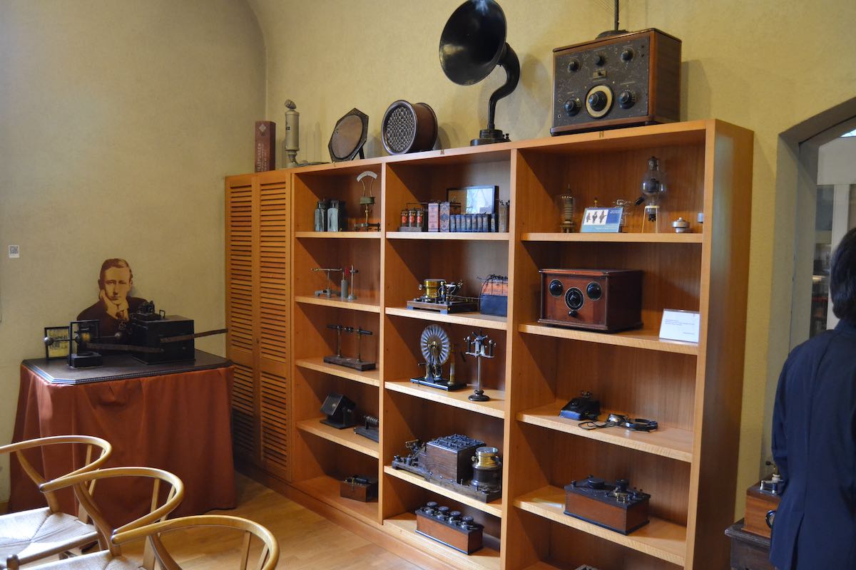
The visit continued to the “silkworm room”, the original room (once used to breed silkworms) where Marconi held his laboratory and performed his experiments. The room was full of instruments replicas to show the laboratory as in the young Marconi years.
“Silkworm room” – Marconi’s first laboratory (original place, instrument replicas)
“Silkworm room” – Marconi’s desk (replica)
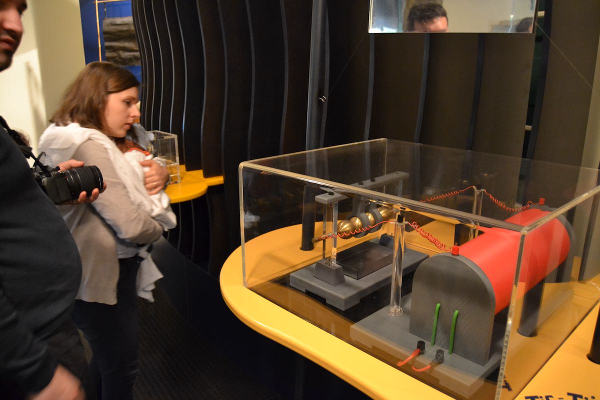
It was also possible to replicate the main experiments with educational working replicas.
Marconi transmitter – educational replica
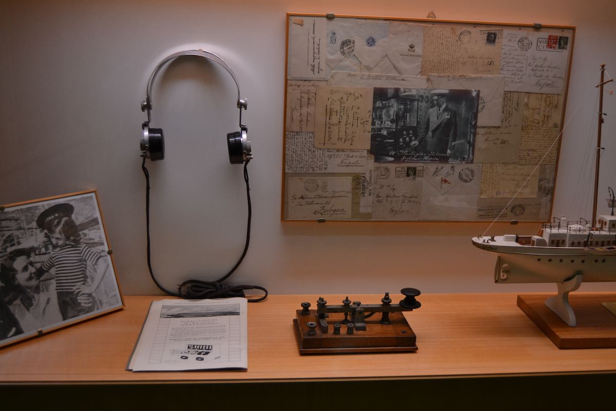
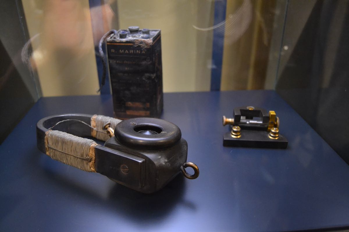
Headphone and coherer used in the first transoceanic transmission (replicas)
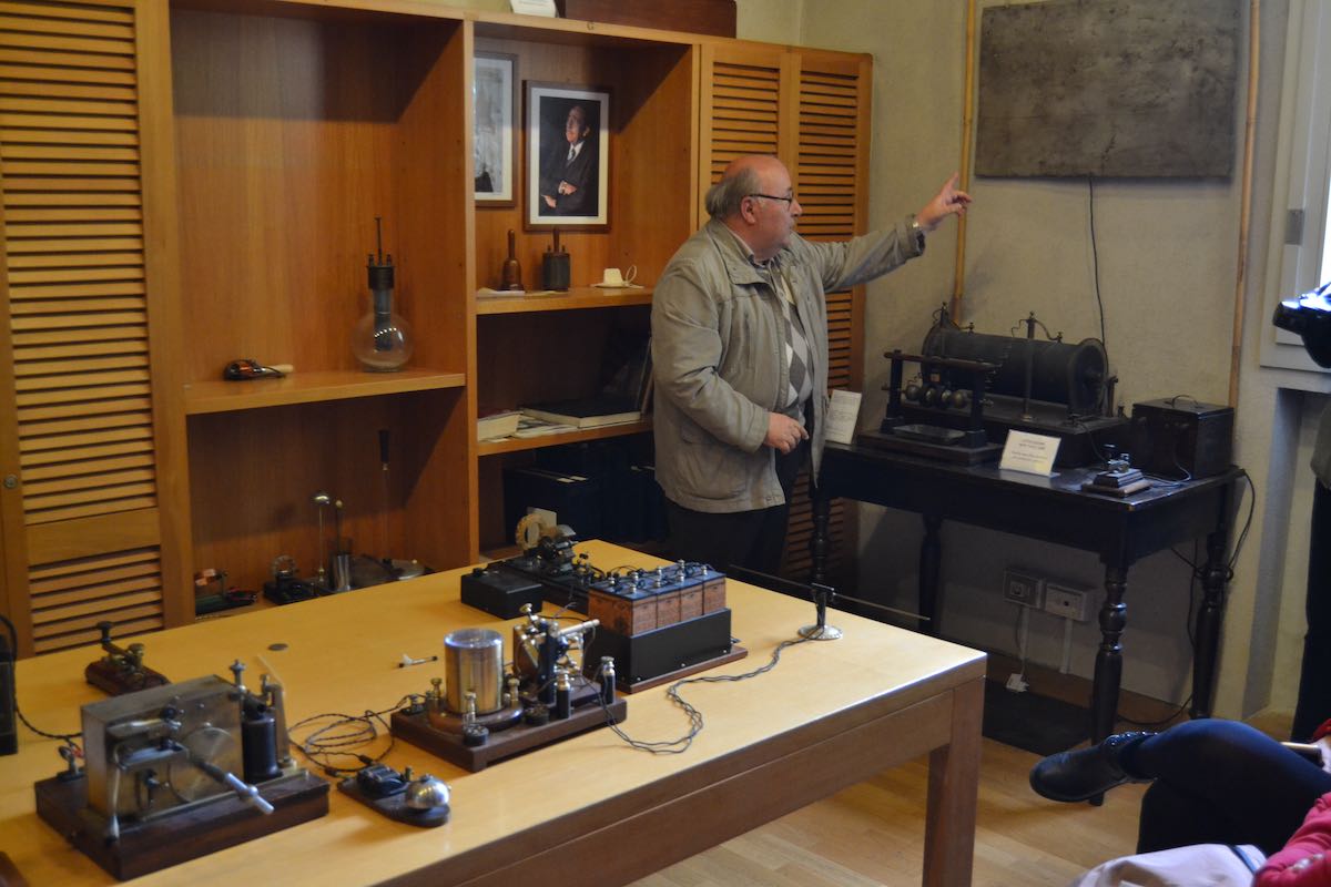
The second phase of the visit was a more engineering-oriented explanation of the principles of radio telegraphy conducted by Adriano Neri I4YCE in a didactic laboratory on working replicas of the main epoch instruments.
Experiment table with working replicas: coherers, a wire decoder, a Marconi receiver
Instruments in the educational laboratory
With passion and competence, Mr. Neri explained us in a simple way (there were some very interested young people in the group) the cable telegraphy principles and the sequence of experiments and discoveries that led Marconi to his inventions.
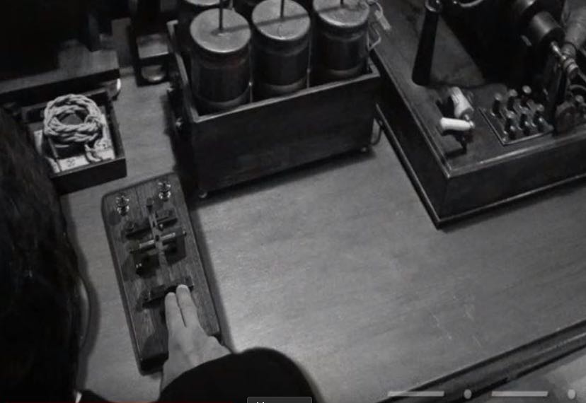
In a detailed and fascinating exposition we saw applications of a Morse writer, the induction coil, the coherer and the first Marconi spark transmitter, all assembled in the end to transmit in the room some morse signals in the air.
Live demonstration of signal transmission by Adriano Neri . Against the wall a Marconi spark transmitter (note the antenna and ground plates), on the table: a Marconi receiver (with a coherer) connected with a Morse writer.
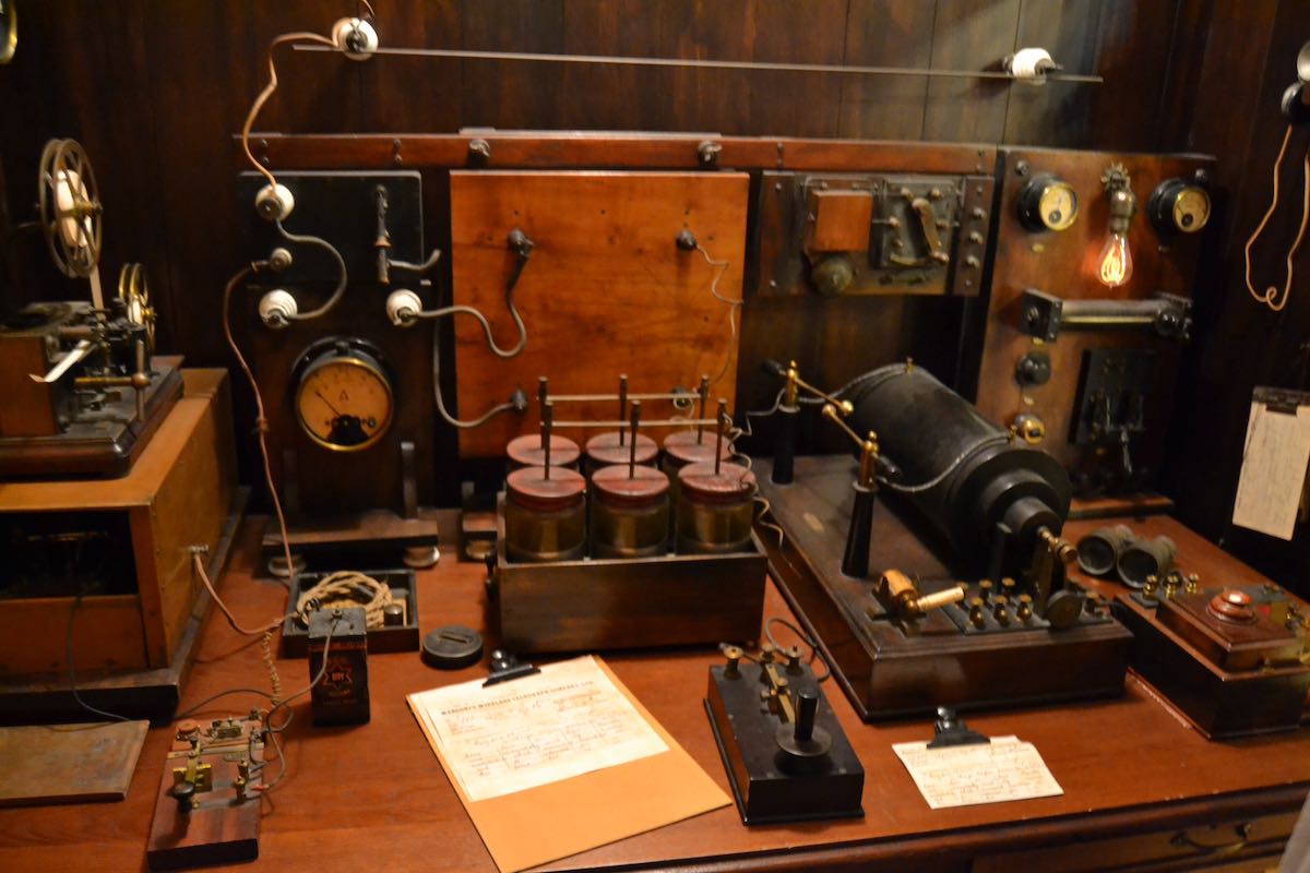
The laboratory, as the whole museum, hosts a huge number of working replicas (a wonderful collection in itself, handmade by Maurizio Bigazzi with rigorous standards of adherence to the original designs and, if possible, reuse of original parts) and some original equipment.
Ship wireless telegraph room – working replica
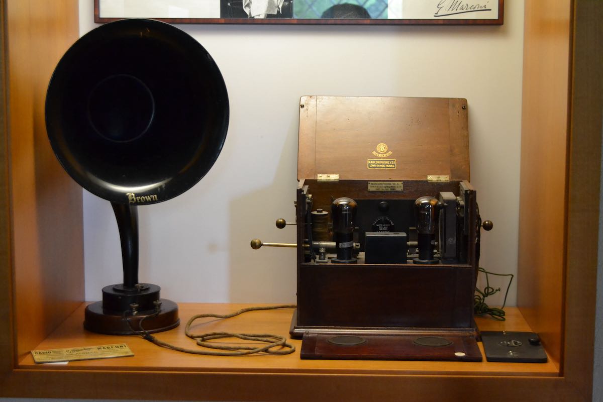
A last section of the museum is devoted to radio communication during the war (showing a WWI airplane-ground communication system) and radio broadcasting, with original sets of great interest like a 1923 Marconiphone (still working, we had a live demonstration receiving RAI programs) and a Ducati radio (the same Ducati company of motorbikes, based in Bologna).
WWI plane radio and ground receiver
1923 Marconiphone, working original set
Ducati radio
We spent all the morning in the Museum with great fun and interest from all the family.
I highly recommend a visit to the Museum for the place, its significance in the history of radio transmission and the competent and passionate exposition of the historical and technical themes related to Guglielmo Marconi.
A wealth of information (also in english) can be found of the Guglielmo Marconi Foundation website (www.fgm.it).
A detailed gallery of the Museum can also be found on the new Museum website (www.museomarconi.it)
Many thanks to SWLing Post contributor, Dan Robinson, for the following guest post and review:
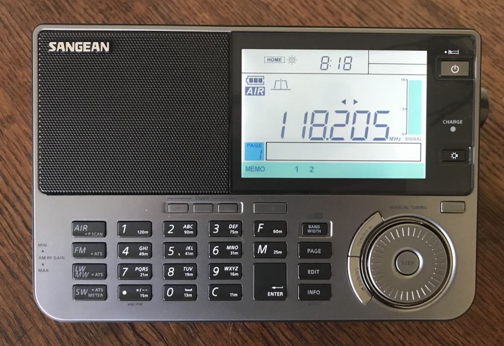
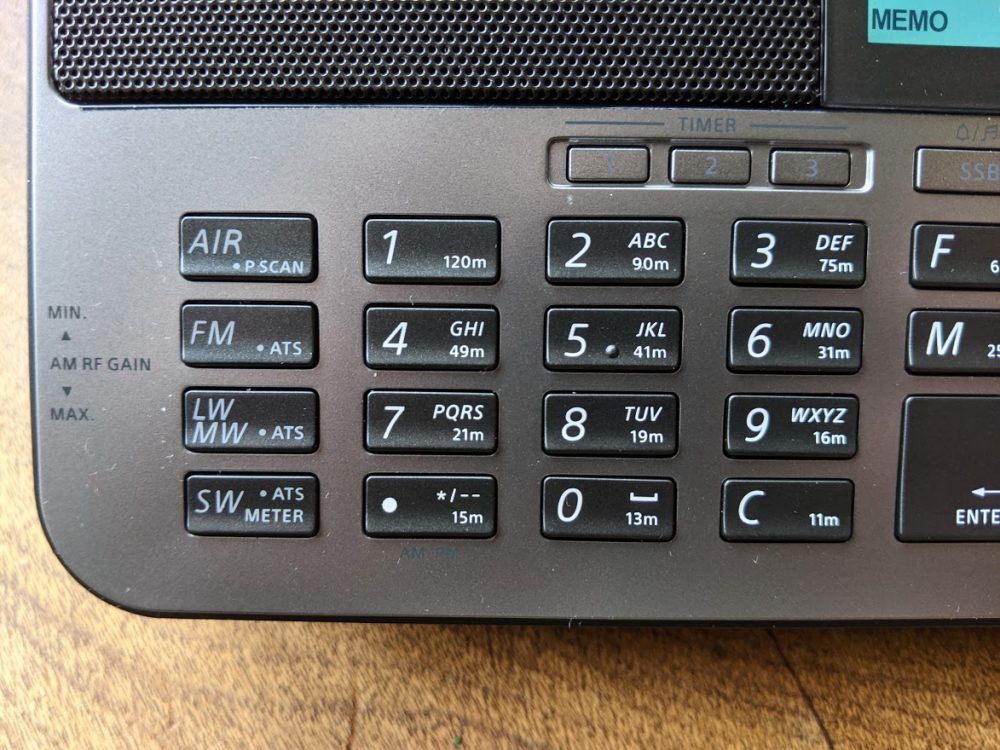
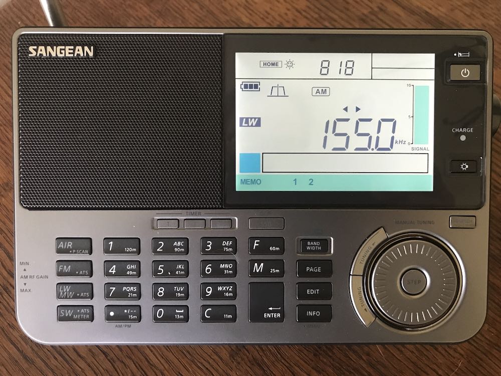
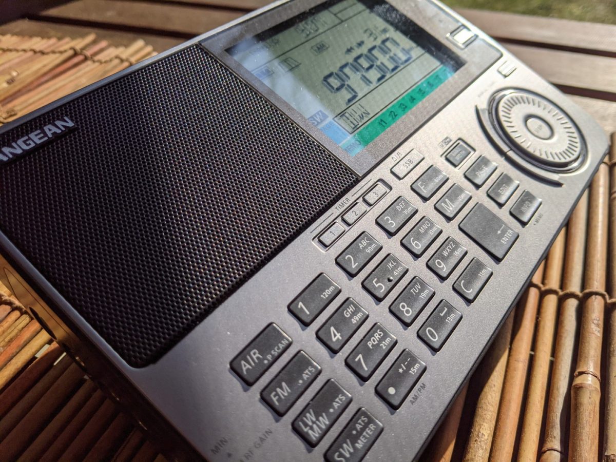
Sangean v Tecsun in the Battle of Late Shortwave Era Portables: The ATS909x2
by Dan Robinson
Some years ago – actually more than a decade – I decided to give Sangean a shot at winning me over in the shortwave portable category.
I had and still do use numerous portables with a bias toward the classic SONY, Panasonic, and Grundig sets. The ones that made an impression stayed, often in multiples, as anyone can see if they visit the radio shack here in Maryland.
These include, for those interested: the Panasonic RF-B65, SONY ICF-SW77, ICF-2010, ICF-PRO80, ICF-7600D, ICF-7700, ICF-SW1000T, ICF-SW55, ICF-SW100s, ICF-SW07, Grundig Satellit 500, to which were added in more recent times the Toshiba RP-F11, XHDATA D-808, and Tecsun portables ranging from the PL-365 and new PL-368 to the PL-880, PL-990x, H-501x, and S-8800.
Sangean has generally not been on that list. There’s a good reason – I just never considered Sangean to be competitive when it comes to portables, though they did have some excellent larger sets such as the ATS-803A that made the first forays into multiple bandwidth options.
My last experience with Sangean was with the ATS-909. I liked the looks and capabilities of that receiver, and even went to the point of having mine modified by Radio Labs. But those mods were underwhelming, in my view, and the original 909 always seemed to me to be deaf when using the whip antenna.
That issue continued unfortunately with the 909x. Some of you may have seen a video I did a few years ago in which I set a 909x against a SONY SW-07 and Panasonic RF-B65. This was done barefoot with only the whip antennas, but near a window. In short, the other two radios wiped the floor with the 909x.
It took a surprisingly long time for Sangean to update the 909x with the 909×2, during which companies asked valid questions about the need for further development of world band portables.
Eton turned the market on its head when it introduced the still superb E1/XM which competed with the very end of SONY portable production, and co-designed with R.L. Drake added such superb features as Passband Tuning and three selectivity positions.
Meanwhile, Tecsun plugged away, introducing an impressive array of portables including the PL-600 series, then the 880 and now the 990x and H-501 portables.
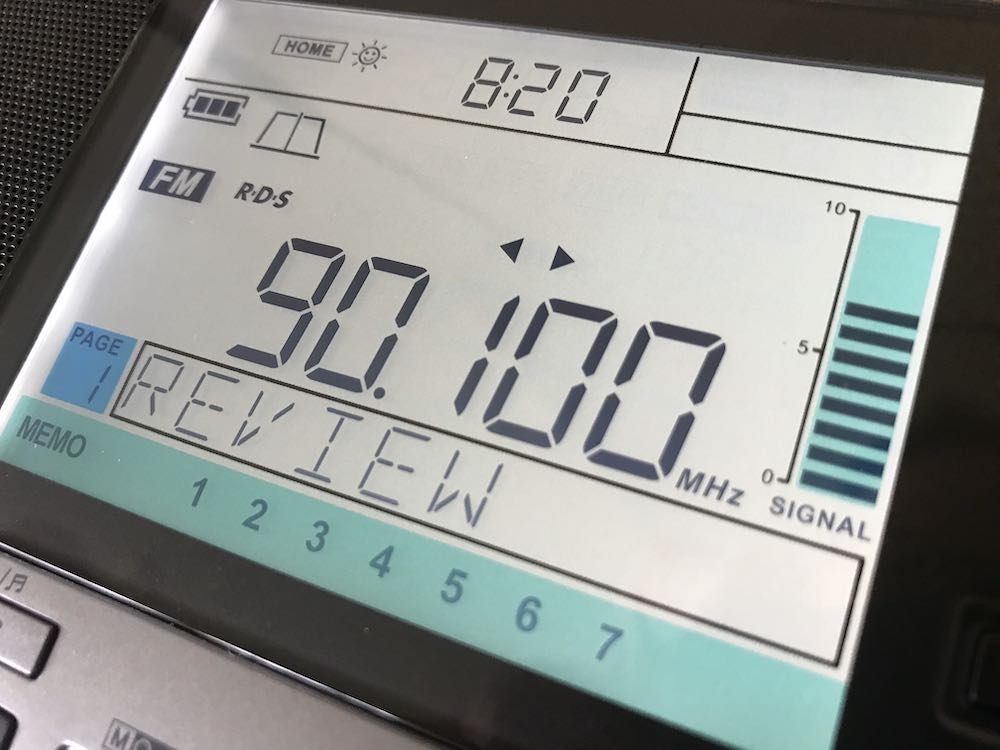
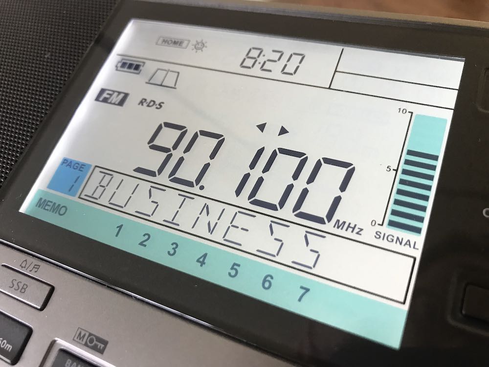
So, now the 909×2 is here and with its 073 firmware upgrade has become a bit of a holy grail for portable receiver users. There have been a number of excellent reviews, including Dave Zantow’s deep dive, and some others here on SWLing Post.
I’m going to give you my impressions, using the really detailed Zantow review as a base. I received my 909×2 from Amazon just today – it is a 073 firmware which confirms that new supplies have the upgrade.
SENSITIVITY ON WHIP
First, let’s get the elephant in the room out of the way. Although I have not undertaken detailed technical testing of the 909×2 – nor do I have the equipment to carry this out – it does seem that Sangean may have finally tackled this crippling flaw that rendered the old 909x nearly useless when using it only on the whip. I’ll undertake further testing and comparisons with some of my other portables to confirm this. The whip antenna itself is robust – solid and long, something that Tecsun could take note of.
AIR BAND
Inclusion of air band on this radio is a major selling point for those interested in this type of monitoring. My initial tests showed the 909×2 to be quite sensitive and useful – I managed to pick up no fewer than five airport comms frequencies in my area here in Maryland.
SELECTIVITY / AUTO-BANDWIDTH
The 909×2 really shines with FIVE available selectivity options that are easily selectable in shortwave mode. It would have been nice to be able to actually see the values of each filter as one scrolls through, but that’s a minor point. Think about it – in shortwave AM mode, this is the number of selectivity positions that one finds on such power house communication receivers as a Drake R8. Amazing that we now have that in a portable. On the negative side, I find the auto-bandwidth feature on the 909×2 to be nearly useless, as useless as the similar feature found on Tecsun receivers. The automatic switching is distracting and annoying. My advice to users: forget this, and stick with manual bandwidth control. My advice to Sangean – I wish they had left this feature out but given us multiple bandwidths in SSB.
LCD AND BRIGHTNESS
Sangean hits it out of the park with this multi-stage lighting for the display. Simply superb and the kind of quality we could only hope for from other manufacturers.
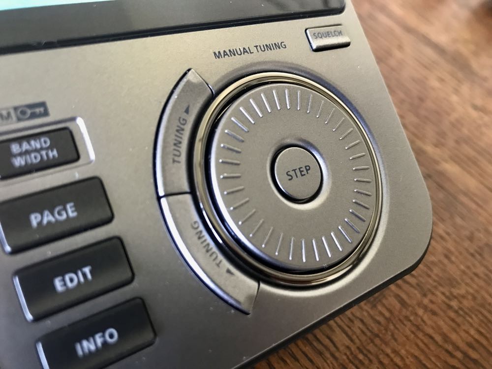
MAIN TUNING / DETENT CONTROL
I found the detents on the old 909x to be annoying – indeed, modifications have been available that could remove this feature. But Sangean being Sangean, the detent wheel remains in the 909×2 and it is not a deal killer.
AUDIO QUALITY
The radio retains the excellent audio of the 909x – I am not sure the 909×2 exceeds what one hears from a Tecsun 990x or H-501x but it’s right up there and competitive.
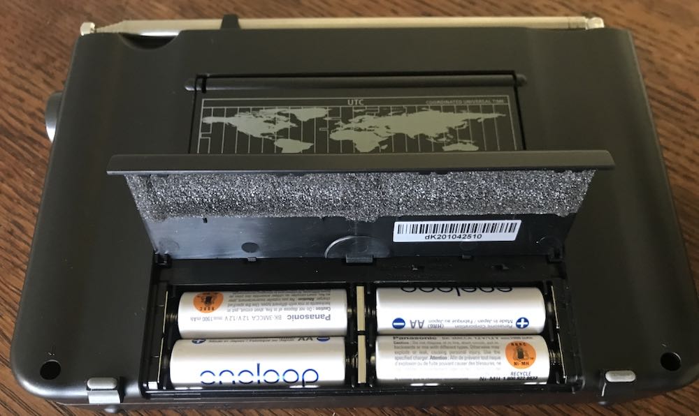
POWER SUPPLY
As others have noted, thanks to Sangean for sticking with AA cells. Together with internal charging when using Ni-Mh cells this is a major selling point. On the other hand – competitor Tecsun went a step farther with its H-501x which though it uses 18650 lithium batteries, has dual batteries, one of which can be held in standby, and switchable charging. That’s a design feature that you really have to respect.
VARIABLE RF GAIN
Again, as noted by others Sangean retained the extremely useful thumb wheel RF gain control. This is an excellent feature.
KEYPAD
Another home run for Sangean when it comes to the keypads on the 909×2, which can be compared in this respect to the Tecsun H-501x which itself improves upon the 990x when it comes to front panel control. Time will tell, however, and we shall see if the keys on these radios hold up in heavy use.
UP/DOWN SLEWING
These controls which sit outside the circular main tuning knob are excellent, and reminds one of the slewing buttons on the SONY 7600GR, SW1000T and SW100.
S-METER / DISPLAY
RSSI and SN Digital Signal Strength Information are provided on the beautiful 909×2 display. This is an improvement over the Tecsun signal strength/SNR meters that I wish would be redesigned, if in fact Tecsun has any intention of future modifications to their portables.
NO SOFT MUTING
Thank goodness we don’t have to deal with the annoying soft muting issue that is still seen in some other portables (the XHDATA D808 comes to mind along with the Eton Executive). Soft muting quite simply ruins a listening session and it’s baffling that any manufacturer still puts it in.
NEGATIVES (I AM IN TEARS)
OK, close all airtight doors and prepare to dive! Here are the negatives I see with the 909×2. I held off obtaining one of these radios because I knew there would be issues. And I was disappointed enough in the past with the 909x and 909 before it that I had almost decided not to go for it.
SIGNS OF LONGWAVE RECEPTION PLAGUED BY CROSS-MOD FROM MEDIUMWAVE
On my particular unit – it remains to be seen whether this is true for others – long wave seems to be near useless. The band is filled with mediumwave stations bleeding through. Turning down the RF obviously helps but I still hear AM stations here in the DC area, when I am in LW mode.
SSB PERFORMANCE
ALERT FOR SANGEAN AND ALMOST A DEAL BREAKER – as mentioned in the Zantow review, and in other comments I have seen on the 909×2, the drop in level from AM to LSB is a killer negative.
This is less noticeable in MW. But if you are in shortwave and have turned your volume up on any particular station, say a strong one such as Greece on 9,420 kHz or Spain, or an AM station, and you then switch to LSB it is like you have almost lost the signal. This simply needs to be fixed. Level on USB seems fine and acceptable, but LSB on shortwave requires immediate upwards adjustment of volume, only to have to reverse the process when returning to AM mode. I find this problem to be sufficiently serious that I would recommend against obtaining a 909×2 until Sangean finds a way to fix it. This issue is on the same level of BAD as the still unsatisfactory SYNC mode in all three of Tecsun’s shortwave portables. In fact, I may return the 909×2 I obtained and wait until a fix for this emerges.
Example Video
In this video, I demonstrate the extent of the problem as seen on this particular unit of the 909×2, which carries a serial number dk201043181.
Dave Zantow says his unit does not have this issue, so there is a possibility this is due to unit to unit variation. As you can see, with a strong signal such as 12,160 kHz — switching from AM to LSB instantly reduces listenable level, and signal as measured on the 909×2 drops to zero bars or near zero. In USB, the reduction is less severe. Regardless, having to perform adjustments with main volume just to struggle to hear any signal in SSB is a bit ridiculous. This kind of thing is not seen on the Tecsun H-501x or 990x though as Dave correctly points out, Tecsun receivers are not exactly great performers in SSB. On Tecsun receivers, there is a slight processor pause while the receiver makes the switch into LSB or USB, without the sharp reduction in listenable level.
CALIBRATION ISSUES WITH NO WAY TO ADJUST
Imagine my joy when I first began using the x2. Initially, it seemed to be smack on frequency – I tried this on WMAL, the powerhouse local AM station here in the DC area, and then again with stronger stations on shortwave, such as 12,160 kHz. Ah, I said to myself, Sangean has some decent QC and paid attention. About 30 minutes later, however, what I found matches the Zantow review. Stations are consistently low of the tuned/displayed frequency by as much as 300 Hz. The reason this is so disappointing is that I feel Sangean could have taken a clue from Tecsun and provided a re-calibration function (unless it exists and we aren’t being told about it). On Tecsun radios, the re-calibration capability is the major counter-punch to poor synchronous mode – in my view, one can live with flawed SYNC on a 990x or H-501 or PL-330 as long as you can adjust and at least have zero beat or close to it across frequencies. At the same time, as Zantow points out, no one should be expecting TCXO level performance from portables such as these. However, it is a bit disappointing that after all these years and redesign of the 909x to add some really nice features, they’re still landing up to 300 Hz from a tuned frequency. On the other hand, is this really any worse than one would see from an off-tuned SONY ICF-2010? No, and adjusting those older receivers required surgery.
CONCLUSIONS
I really like the 909×2. There simply is something about this design that Sangean knew was a winner when it first arrived on the market years ago, so it’s not surprising that Sangean stuck with it. It’s clear that some hard thinking went into the step up from the old 909x, notably the larger LCD, addition of finer step tuning to make SSB easier, the robust antenna and the still pretty darn good audio through the wonderful speaker. The 909×2 is a radio that you can imagine guests would comment on if it were sitting on your coffee table – it just looks THAT GOOD.
But then here in 2021, so does a Tecsun H-501x LOOK THAT GOOD. As I noted above, where the Tecsuns fall down – with their still challenged synchronous mode – they make up for with the ability to re-calibrate.
That is a huge feature and one that Sangean struck out on, though surely Sangean designers had to know the 909×2 would appeal both to listeners and to hobbyists with obsessions about frequency accuracy.
To repeat, I really (really) like the 909×2. But another area where the receiver strikes out is the problem with sharp reduction in LSB mode. Seriously – you have to crank the volume control up to at least 50 percent to hear ANYTHING when you’re in LSB, whereas USB requires going only up to about 30 percent. Then when you’re completing your carousel back to AM, you have to be sure not to still have the audio up at 50 percent or more to avoid blowing your speaker.
Again, as I said above, the calibration/drift issue on the 909×2 can be lived with. The problem with LSB, in my opinion, cannot or should not be tolerated. So, the question is, do you want to purchase a 909×2 now that still has that LSB audio issue, or wait a while until Sangean gets its act together?
These and other earthshaking questions are before us here in 2021. We have some of the best portables ever made by anyone in a time of sharply declining shortwave use, but they each have their flaws.
I don’t usually do a star rating or RECOMMEND / NOT RECOMMEND for radios. This time, I am going to make an exception and it links directly to the issue of the LSB problem on the 909×2. These radios simply should not have been allowed to enter the market with this being as serious a problem as I think it is. For that reason, I honestly cannot recommend a Sangean 909×2 until this is corrected.
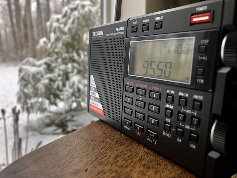
Many thanks to SWLing Post contributor, Mad Radio DXer, who writes:
Hi,
I want to let you & your readers know of a Tecsun PL-330 trick that I saw mentioned in the comments section of your blog some time ago which does not seem to have a lot of awareness. This is for using the telescopic antenna for the LW & MW bands, & it works for the 3305 version of the PL-330 which I understand is the export version. The original comment I saw said this also works for the Chinese version of the PL-330, before firmware 3305.
It is very easy to do & instructions are the following…
1. Turn on the radio.
2. Select either the MW or LW band.
3. Press the number 3 key down for a few seconds, until the display shows “CH-S”.
This means the MW & LW bands can now be received with the telescopic antenna.
4. To use the ferrite bar again, press the number 3 key until “CH-A” appears on screen.
This reminds me of the trick used for the Degen DE1103 PLL version which allows reception of the telescopic antenna for the MW band. However, in my opinion this is much easier to use on the PL-330 than the DE1103 PLL which could be very fiddly. Also this trick is most effective on the LW band, as I find Chinese portables are usually very weak on this part of the band which is good news for LW DXers. I hope you & everyone reading find this trick very useful & that it works.