Shortwave listening and everything radio including reviews, broadcasting, ham radio, field operation, DXing, maker kits, travel, emergency gear, events, and more
In 2019, shortly after Icom announced the Icom IC-705, I speculated that this rig might be a contender for “Holy Grail” status.
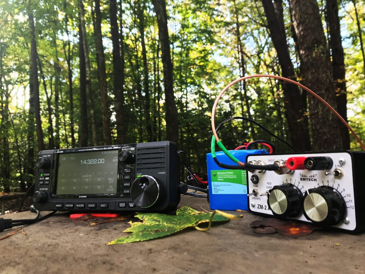
I must admit…the more I use this radio, the more I love it. It is a proper Swiss Army Knife of a radio. Even though I’ve owned and operated it for a few months, I still haven’t explored all that it can do, and I keep finding features I love.
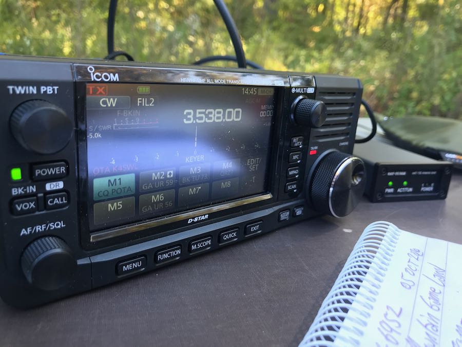
After completing the upgrade, I hooked the ‘705 up to my main antenna and worked a few Parks On The Air (POTA) stations off of the supplied battery pack (instead of a power supply). While I worked on other projects in the shack, I checked the POTA spots and work a few stations with a whopping 5 watts of output power.
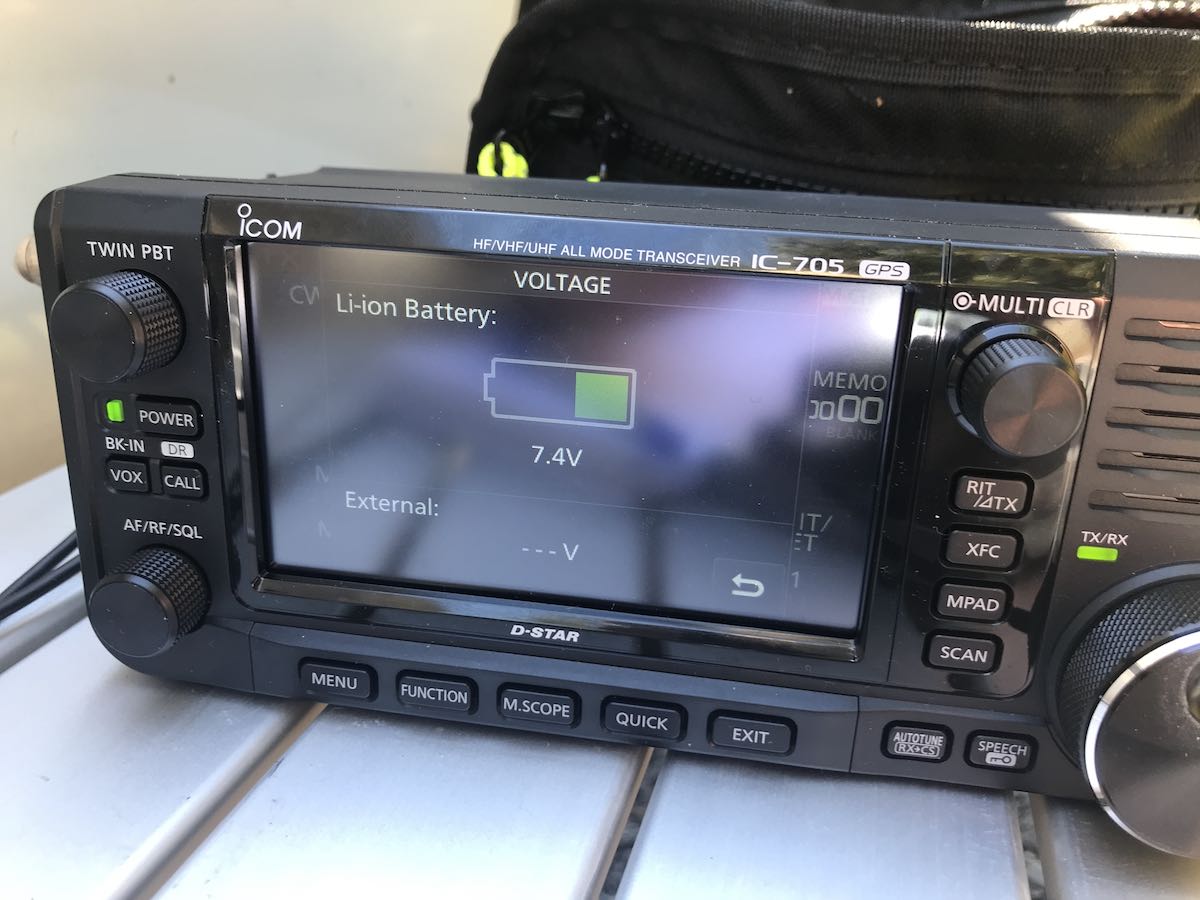
After a couple hours on the air (mostly listening), the internal battery pack still had a good 60-70% capacity.
At one point, I tried a little daytime mediumwave DXing and cruised past 630 kHz which some of you might already know is the home of one of my favorite hometown radio stations, WAIZ.
From my home, WAIZ is a tough catch, so it was weak, but I could hear it.
This reminded me that I had made a recording of WAIZ with the IC-705 when in my hometown earlier this month.
Normally, I pull the MicroSD card out of the IC-705–which almost requires needle nose pliers and is one of my few complaints about this rig–and view the files on my PC or MacBook, but I was curious if perhaps the IC-705 software had a built-in file display.
Of course it does!
Simply press the MENU button, then the RECORD button on the touch screen, and you’ll see the following selections:
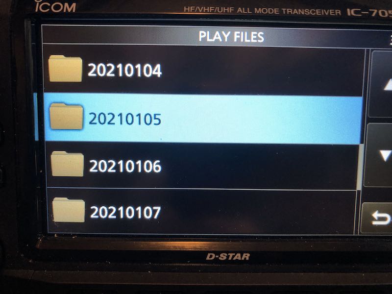
Press “Play Files” and you then see a list of folders organized by date:
Click on a folder and you’ll see a list of recordings made that day:
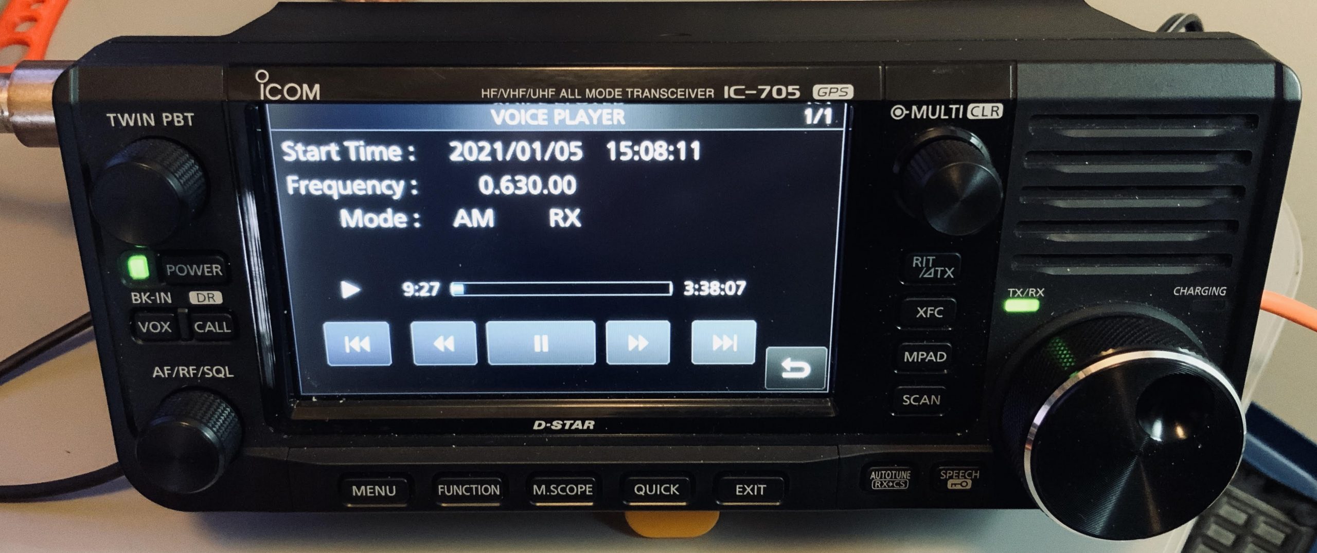
These are some of the most important pieces of information I use to index my audio recordings and the IC-705 does this automatically. In fact, if you allow the IC-705 to gather its time information from the internal GPS, the time stamp will be incredibly accurate.
The only thing I add to the file name after export is the broadcaster name/station callsign.
If that wasn’t enough, if you touch one of the recording files, the IC-705 will open it in an audio player:
The built-in player displays the meta data, and even includes a number of controls like fast-forward, rewind, skip to next or previous file. and pause.
I’m sure this is the same audio player found in the IC-7300, IC-R8600 and other late-model Icom SDR rigs. But in a portable battery powered transceiver? This is a genius feature.
As I type this post I’m listening to the audio from the WAIZ file shown above. I can imagine when I’m able to travel again (post-pandemic), how useful this will for one-bag air travel.
Not only is the IC-705 a QRP transceiver and wideband multi-mode general coverage receiver, but it’s a recorder and audio player with a built-in front-facing speaker. I can set this transceiver at my hotel bedside and listen to recordings I made in the field earlier that day or week.
Keep in mind that the IC-705 is an expensive radio–certainly one of the most pricey QRP radios ever produced at $1,300 US (at time of posting although I’m sure we’ll start seeing lower pricing this year). But if you’re an SWL and ham, you’ll find the IC-705 is the most versatile portable transceiver on the market. If you’re an SWL only, you can disable the transmit on the IC-705 and essentially have a portable battery-powered SDR receiver with built-in audio recording and playback with color touch screen spectrum and waterfall display.
Despite the price, this is Holy Grail territory in my book.
Icom IC-705 Review
If you subscribe to The Spectrum Monitor magazine, you’ll be able to read my (4,000 word!) review of the IC-705 in the upcoming February 2021 issue.
Many thanks to SWLing Post contributor, Kostas (SV3ORA), for sharing the following guest post which originally appeared on his radio website:
Emergency transmitter: An 8-component, high-power 40m/30m transmitter to get you quickly on the air
by Kostas (SV3ORA)
Introduction
QRP is all about doing more with less. This is more than true, with the construction of this cheap, simplistic transmitter presented here. It is designed primarily as an emergency transmitter (EMTX) that can be built or serviced in the field or at any home. However, it can be used as a HAM radio transmitter as well. Do not judge by its low components count though. This transmitter is powerful, more powerful than anything the QRPers would dream of. It is just remarkable how 8 components can lead in so much output power, that lets you communicate with a big part of the world, when propagation conditions are right. It is very difficult for a circuit to match that kind of simplicity in balance with such performance.
Following my detailed instructions, the EMTX can be reproduced easily, within hours. The result is always success, this is one of the circuits that are not critical at all and a successfully working transmitter can be reproduced every time. I have built this transmitter several times, using similar components (even toroids) and it always worked. The transmitter meets the next expectations:
1. Output power (including harmonics): A few mW up to 15W (depended on transistor, crystals and voltage/current used) at 50 ohm.
2. It can drive any antenna directly, 50 ohm or higher impedance, without external tuners.
3. Bands of operation: Currently 40m, 30m
4. Mode: CW, Feld-Hell (with external switching circuit), TAP code and any other ON/OFF keying mode. AM modulation has been easily applied too.
5. Options like reverse polarity protection diode (useful in the field when testing different unknown polarities PSUs) and current meter (for easier tuning) are available.
The challenge
The purpose of this transmitter is to be used primarily as an emergency transmitter. This poses several challenges that influence the design of the transmitter:
1. It must be able to be built or serviced easily in the field or at any home, with components that could be salvaged from near by electronics sources or a small electronics junk box. This means that components count should be kept very low and they must not be rare to find but commonly available parts. As a side effect cost would also be kept small, if one is to buy any component. Also, the active components must be interchangable with many other devices without the need for the design or the rest of the circuit components to be changed.
2. It must be able to operate from a very wide range of DC voltage sources and at relatively low current, so that common house power supplies could be used to supply power to it. Such devices include linear or switched mode power supplies from laptop computers, routers, printers, cell phone chargers, Christmas lights or any other device one might have available.
3. It must be capable of transmitting a powerful signal, so that communication is ensured. An emergency transmitter that is capable of a few mW of output power, might be heard locally (still useful, but there are handheld devices for that already) but isn’t going to be of much usage if it can’t be heard really far away.
4. It must be capable of loading any antenna without external equipment required. In an emergency situation, you just don’t have the luxury of building nice antennas or carrying coaxial cables and tuners. There may be even extreme cases where you can’t even carry a wire antenna and you depend on salvaging wire from sources in the field to put out a quick and dirty random wire antenna.
5. Adjustments of the transmitter should be kept minimum without the help of any external equipment and there must be indication of the correct operation of the transmitter or the antenna in the field.
Components selection
The transistor:
This transmitter has been designed so that it can operate with any NPN BJT in place. This includes small signal RF and audio transistors and high power RF transistors like the ones used on HF amplifiers and CB radios. Despite 2sc2078 is shown in the schematic, just try any NPN BJT in place and adjust the variable capacitor accordingly. When you are in the field, you do not have the luxury of finding special types of transistors. The transmitter must operate with any transistor in hand, or salvaged from near-by equipment. Of course the power capability of the transistor (as well as the crystal current handling) will determine the maximum VCC and current that can be applied to it and hence the maximum output power of the transmitter. Some of the most powerful transistors I have used, come out of old CB radios, such as the 2sc2078, 2sc2166, 2sc1971, 2sc3133, 2sc1969 and 2sc2312. There are many others. As an example, the 2sc2078 with a 20v laptop PSU, gave 10-12W of maximum output power into a 50 ohms load.
Schematic of the 8 components EMTX for the 40m/30m bands. Components with gray color are optional.
The crystal:
This is the most uncommon part of the transmitter. You have to find the crystal for the frequency that you want to operate on. Crystals within the 40m or 30m CW segments are not that common. Further more if you operate the transmitter at high powers and currents, you will notice crystal heating and chirp on the frequency of the transmitter. The current handling capability of your crystal die inside the crystal case, will determine the chirp and the amount of crystal heating. You can still work stations with a chirpy transmitter provided that the chirp is not that high, so that it can pass through the CW filters of the receivers. However, if a small chirp annoys you or if this chirp is too much, then you have to use these vintage bigger size crystals (e.g. FT-243), that can handle more current through them. But these are even more uncommon today.
The approach I have used in my prototype, was to connect more than one HC-49U crystals of the same frequency in parallel, so that the current is shared among them. This reduced the chirp at almost unnoticeable levels, even at high output power, just if I was using a single FT-243 crystal, or even better in some cases. Again, this is optional, but if you want to minimize chirp (and crystal heating) without searching for rare vintage crystals, this is the way to go.
A bit of warning. If you notice a very high chirp when plugging in a crystal to the EMTX, you should consider this crystal as inappropriate for this transmitter, as it cannot handle the current required. If you continue to use this inappropriate crystal, you could easily crack it inside and set it useless. Don’t use these tiny HC-49S crystals, they won’t work.
The current meter:
A 1Amp (or even larger) current meter can be used to monitor the current drawn by the transmitter during key down. The recommended current operating point is anywhere between 450mA to 1A, depended on the output power (and harmonics) level you want to achieve. The current point is set by the variable capacitor. I would avoid setting the current to more than 1Amp, although it can be done. The use of the current meter is optional, but along with the incandescent bulb, will give you a nice indication of the correct tuning of the transmitter, so that you do not need to have an external RF power meter connected to the transmitter output. If you do have, then you can remove the current meter. If you don’t have a 1Amp analogue meter available, but a smaller one, you can parallel a low value power resistor across the meter. In my case, I only had a 100uA meter and I paralleled a 0.15 ohms 5W resistor across it to scale down 1Amp to 100uA, The resistor value depends on the internal meter resistance so you have to calculate this for your specific meter. When the 2sc2078 is used at 20V, 500mA in the current meter indicates around 5W of output power, 600mA indicates around 6W, 700mA 7W, 800mA 8W, 900mA 9W and 1A around 10W. So the current meter can be used as sort of power meter without the need to do any scaling on it.
The incandescent bulb:
A current meter alone, without the use of the incandescent bulb, will not give you the right indication of the operation of the transmitter. In some cases, the transmitter might be drawing current without actually generating much, or even any RF. When you are in the field you do not want to carry extra monitoring equipment with you. The incandescent bulb will light on when the transmitter oscillates. It monitors the actual RF signal, so it’s brightness changes according to the amount of RF power the transmitter produces. Along with the current meter reading, this is just what you need to know in order to set the variable capacitor properly. Note that the bulb will not lit at very low signal levels. The one used in the prototype starts to glow up from a bit less than 1W. Miniature incandescent bulbs may not be that easy to find nowadays. However, there is a good source of these, that almost anyone has in their houses. This source is the old Christmas lights. You do save old Christmas lights, don’t you? The incandescent bulb indicator as well as it’s single turn winding on the transformer, are optional components. If you have an RF power meter connected to the transmitter, you can remove these.
The diode:
The protection diode is an optional component to the circuit. If you are in the field, correct polarity of a power supply may not be obvious. Without a multimeter it might me difficult to determine the correct polarity of the PSU. A power diode (I used a 6A one) will protect the transistor from blowing up in the event that reverse polarity is connected to the circuit.
The Cx and Cy:
The Cx and especially the Cy capacitors need to be of good quality. The Cy will get hot on high output power if it isn’t. In the tests, I have used homemade gimmick capacitor and even double-sided PCB as a capacitor for Cy and they all got hot at high power. Silver mica capacitors run much cooler and they do make a small difference in the output power, so I suggest to this type. Cy must be able to handle quite a lot of voltage, so silver mica type is ideal.
The variable capacitor:
The variable capacitor can be air variable or ceramic, although I prefer air variables in tis application. In any case it must be able to handle a high voltage just as the Cy.
The key:
The key directly shorts the transistor emitter to the ground, therefore it is a part of the active circuit. For this reason, I suggest the key leads to be kept as short as possible. The key must be able to handle the voltage (20v) and current (up to 1A) on its contacts, which is usually not a big deal.
Transformer construction
The construction of the transformer is shown below step by step. Note that if you decide that you don’t need to drive higher impedance loads but just 50 ohm ones (eg. antenna tuners or 50 ohm matched antennas), you just need to wind 2t in the secondary and not 14t. You also don’t need any taps of course.
Step 1:
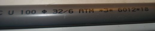
Take a piece of 32mm external diameter PVC pipe from a plumber’s shop. Alternatively, a suitable diameter pills box can be used, or any other suitable diameter plastic tube.
Step 2:
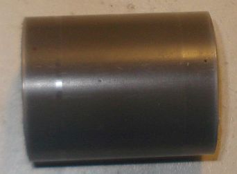
Cut a 4cm piece out of this tube. 4cm is the minimum length required.
Below a 4cm PVC tube has been cut in size.
Step 3:
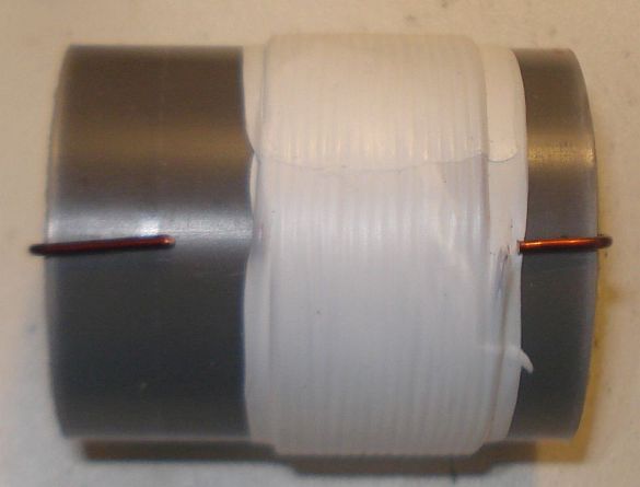
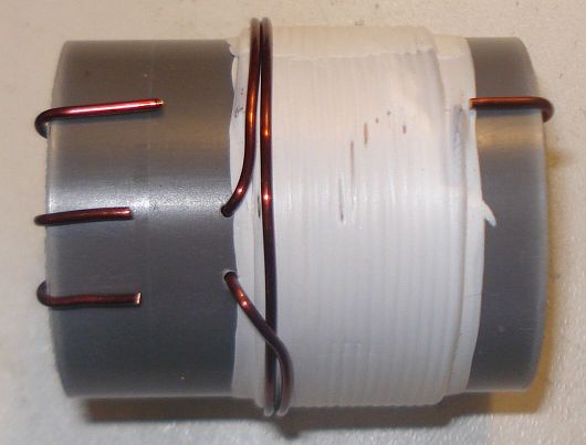
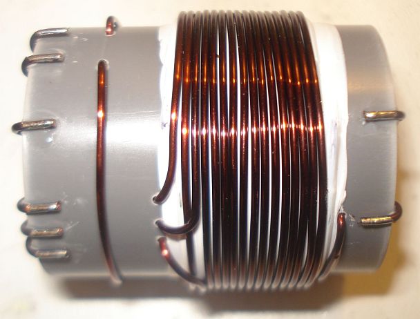
Wind 16 turns of 1mm diameter enameled wire onto the PVC pipe and secure the winding in place as shown in the picture below. Notice the winding direction of the wire. This is the primary of the transformer, the one that is connected to the two capacitors. Notice that this winding is wound a bit offset to the right of the pipe.
Step 4:
Wrap the winding with 3 turns of PTFE tape. It can be bought at any plumber’s shop, just like the PVC pipe. The PTFE tape will help in keeping the second layer turns in place and it will provide extra insulation.
Step 5:
Wind 2 turns of 1mm diameter enameled wire on top of the primary winding and secure the winding in place as shown in the picture below. Notice the winding direction of the wire, as well as it’s position relative to the primary winding. This is the feedback of the transformer, the one that is connected to the collector of the transistor.
Step 6:
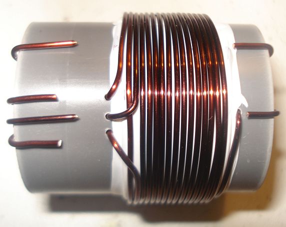
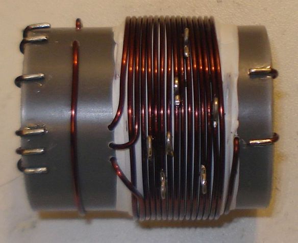
Wind 14 turns of 1mm diameter enameled wire on top of the primary winding, starting from just next to the 2 turns one and secure this winding in place as shown in the picture below. Notice the winding direction of the wire, as well as its position relative to the primary and the 2 turns windings. This is the secondary (output) of the transformer, the one that is connected to the antenna. At this point do not worry about the taps yet.
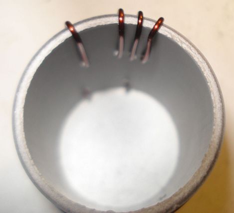
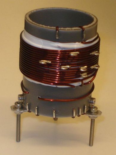
Notice in the picture below, the way the windings are secured in place onto the pipe. The wire ends are passed through the pipe using small holes and then bent towards the ends of the pipe and once more to the surface of the pipe, where the connections will be made.
Step 7:
Wind 1 turn of 1mm diameter enameled wire onto the pipe and secure the winding in place as shown in the picture below. Notice the winding position relative to the other windings. This 1 turn winding is placed about 1cm away from the other windings. This is the RF pick up winding, the one that is connected to the incandescent bulb.
Step 8:
Use a sharp cutter (knife) and carefully scrap the enamel of all the windings ends. Do not worry if you cannot scrap the enamel at the bottom side of the wire ends (that touches to the pipe). We just want enough copper exposed to make the connection.
Step 9:
Tin the scrapped wire ends, taking care not to overheat them much.
Step 10:
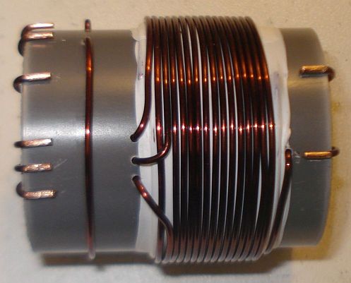
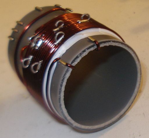
Now it’s time to make the taps on the secondary winding. Use a sharp cutter (knife) and very carefully scrap the enamel of the wire at the tap points (number of turns). Take much care not to scrap the enamel of the previous and the next turn from each tap point. Do not worry if you just scrap the enamel at the top of the wire (external area). We just want enough copper exposed to make the connection.
Make each tap, a bit offset from the near by taps, like shown in the pictures. This will avoid any short circuits (especially at the 4, 5 and 6 taps) and it will allow for easier connections, especially if alligator clips are used to connect to the taps.
Step 11:
Tin all the tap points, taking care not to overheat them.
Step 12:
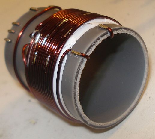
This step is optional and it depends on how you decide to do the connections to the taps. You may solder wires directly to the tap points, but in my case I wanted to use alligator clips, so I did the next: I took a piece of a component lead and soldered it’s one end to each tap point. Then I bent the component lead to U-shape and cut it accordingly. This created nice and rigid tap points for the alligator clip.
Step 13:
This step is optional and it depends on how you decide to mount the transformer to your enclosure. In my case, I wanted to create three small legs for the mounting. I cut three pieces of aluminum straps and made holes at both their ends. I made three small holes onto the transformer pipe end and mounted the aluminum straps using screws. After mounting them, I shaped the straps to L-shape. Then I used three more screws to mount the transformer to the enclosure.
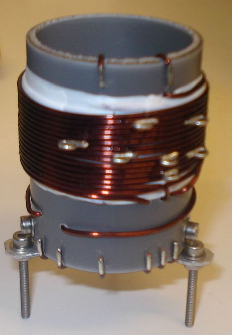
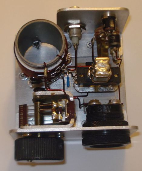
The completed transformer is shown in the pictures above and below. The 6 connection points at the bottom of the pipe, are the low voltage points, whereas the 2 points at the top of the pipe, are the high voltage points.
If you have built the transformer as described, the bottom connections are as follows (from left to right):
Wire end 1, connected to the incandescent bulb
Wire end 2, connected to the incandescent bulb
Wire end 3, connected to the current meter
Wire end 4, connected to the current meter
Wire end 5, connected to the GND (ground)
Wire end 6, connected to the transistor collector
The top connections are as follows (from left to right):
Wire end 1, connected to the 25pF variable capacitor and the Cy fixed.
Wire end 2, is the 14th secondary tap and it is left unconnected, or tapped to the appropriate impedance antenna.
Videos of the EMTX in operation
I have made two small videos of the EMTX in operation.
The first 13.5MB video (right click to download), shows the operation when the transmitter is set for a bit less than 10W of output power.
The second 3.5MB video (right click to download), shows the operation when the transmitter is set for about 5W of output power.
EMTX chirp analysis
Every self-exited power oscillator (and even many multi-stage designs) exhibits some amount of chirp. Chirp is mainly considered as the sudden change in frequency when the power oscillator is keyed down. Apart from chirp, there is also the longer term frequency stability that may be considered. The chirp in the EMTX is surprisingly low, if it is built properly. Hans Summers, G0UPL has performed a chirp analysis on my EMTX (PDF) and the EMTX built by VK3YE and presented on YouTube. Hans, performed the analysis from the video/audio recordings of both transmitters. I sent him two videos, one with the EMTX set for an output power of 10W and one where it is set for 5W. The chirp at worst case (10W) was about 30Hz and at 5W in the order of 10Hz or so. Being so small, the chirp is almost undetectable by the ear and it surely poses no problems when passing the tone through narrow CW filters. This is an amazing accomplishment from a transmitter so simple and so powerful.
EMTX harmonics measurement
Every unfiltered transmitter will excibit harmonics at it’s output. This means that the output waveform has some distortion in comparison to a pure sinewave. Many of the transmitters I have seen, present a very distorted output waveform and absolutely need a LPF if they are to be connected to an antenna. I can’t say that this is true for the EMTX, because surprizingly, it has low distordion, despite the high output power it can achieve. Although a LPF is always a good idea, it is not that much needed on the EMTX. However you have to use one to comply with the regulations.
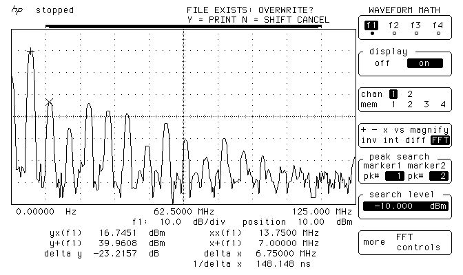
The image above, shows the measurements on the output of the EMTX, when it is set closely to 10W at 50 ohms. The main carrier is exactly at 9.9W and all the harmonics are less than 50mW! Also, the harmonics, do not extend into the VHF region.
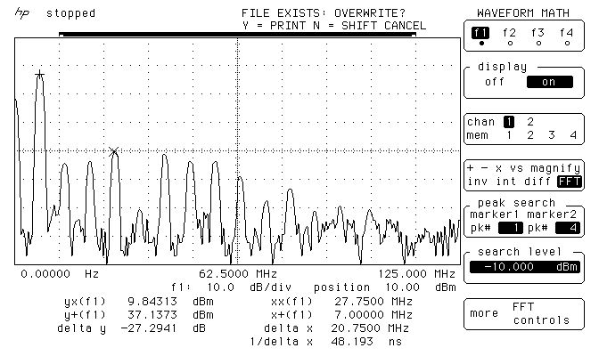
The image below, shows the measurements on the output of the EMTX, when it is set closely to 5W at 50 ohms. The main carrier is exactly at 5.17W and all the harmonics are less than 9.6mW! Again, the harmonics, do not extend into the VHF region.
These small harmonics levels aren’t going to be heard very far at all, compared to the powerful carrier. This means only one thing. A LPF, although a good practice, is not mandatory in this transmitter. But you should better use one so that you comply with the regulations.
Many HAMs use just a watt meter to measure the output of their homebrew transmitters. This is not the proper way of doing it, because the watt meter is a non-selective meter. It will measure both the fundamental carrier and the harmonics, without being able to distinguish them. So in an unfiltered transmitter, or in a transmitter with a simple (often non measured) LPF, this way will give a totally false reading of the output power of the transmitter at the set frequency.
The proper way of accurately measuring the output power of a transmitter and the harmonics levels, is a spectrum analyzer. The FFT available in many modern oscilloscopes, having a dynamic range of approximately 50-55dB, is adequate for this purpose as well. A 50 ohms dummy load must be connected at the transmitter output and then the high impedance probe of the scope, is connected to the output of the transmitter as well. This was the way that the above measurements have been performed.
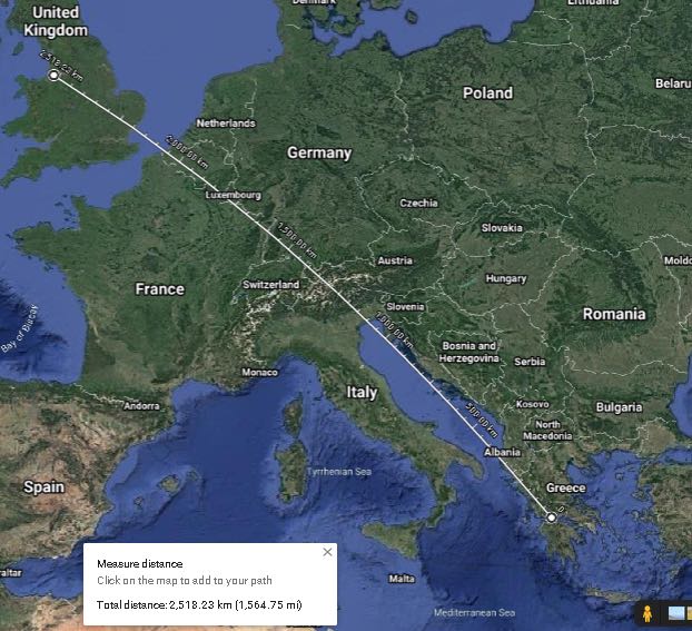
WebSDR tests
Here are some test transmissions, to determine how far one can get with such a transmitter. I have to say that there is an antenna tuner between the EMTX and my inefficient short dipole (not cut for 40m and not even matched to the coaxial). However I could still cover a distance of more than 2500Km even on the 5W setting.
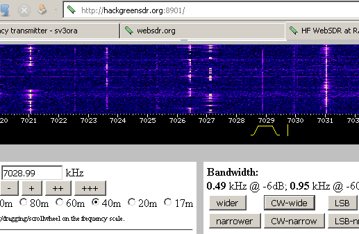
A screenshot of the transmitter signal, as received on a WebSDR 2500Km away and when the EMTX is set for an output power of 10W.
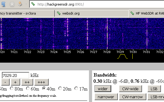
Below, is a picture and an audio recording of the transmitter signal, as received on the same WebSDR and when the EMTX is set for an output power of 5W.
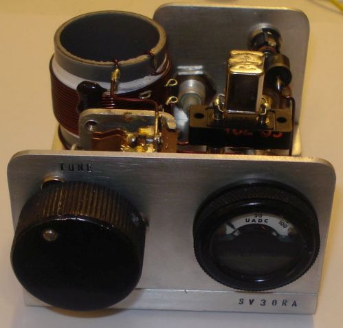
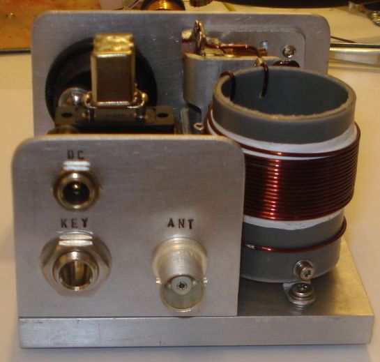
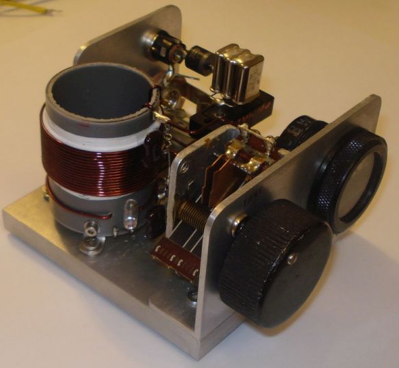
Photos
Pictures of the finished transmitter. You don’t have to build it that nice-looking if you don’t care.
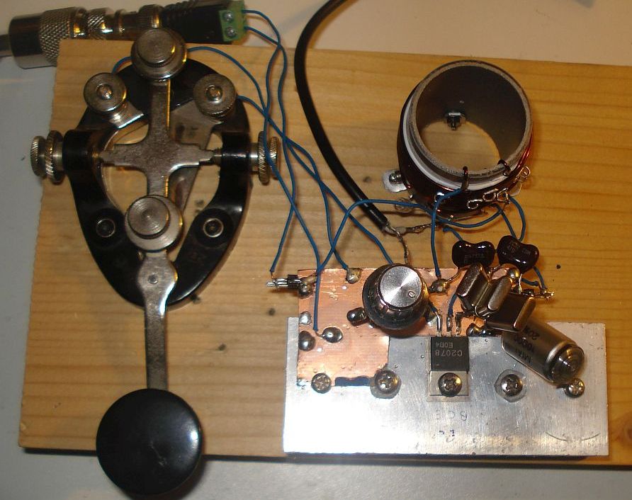
EMTX prototype built on a breadboard. Yes it worked just fine onto a piece of wood.
This is a phenomenal project, Kostas. Thank you so much for sharing it with us. I love the simplicity of this design–truly form following function. With a little patience, anyone could build this transmitter.
This morning, I’m looking at the calendar and I see and end in sight for 2020. I think most of us can agree that 2020 will be one for the history books, in large part due to the Covid-19 global pandemic which has had a pretty dramatic affect on many of our lives. It certainly brough my planned travels to a halt. I think many of us are quite happy to show 2020 the door!
As each year comes to a conclusion, I often look back at my radio activities during that year and see how it played out. I especially note the radios I used most heavily throughout the year.
Since I evaluate and test radios, models that are new to the market obviously get a lot of air time. Still, I’m also known to pull radios from the closet and give them some serous air time.
I’m very curious what radios you gave the most air time in 2020?
Here’s my list based on type/application:
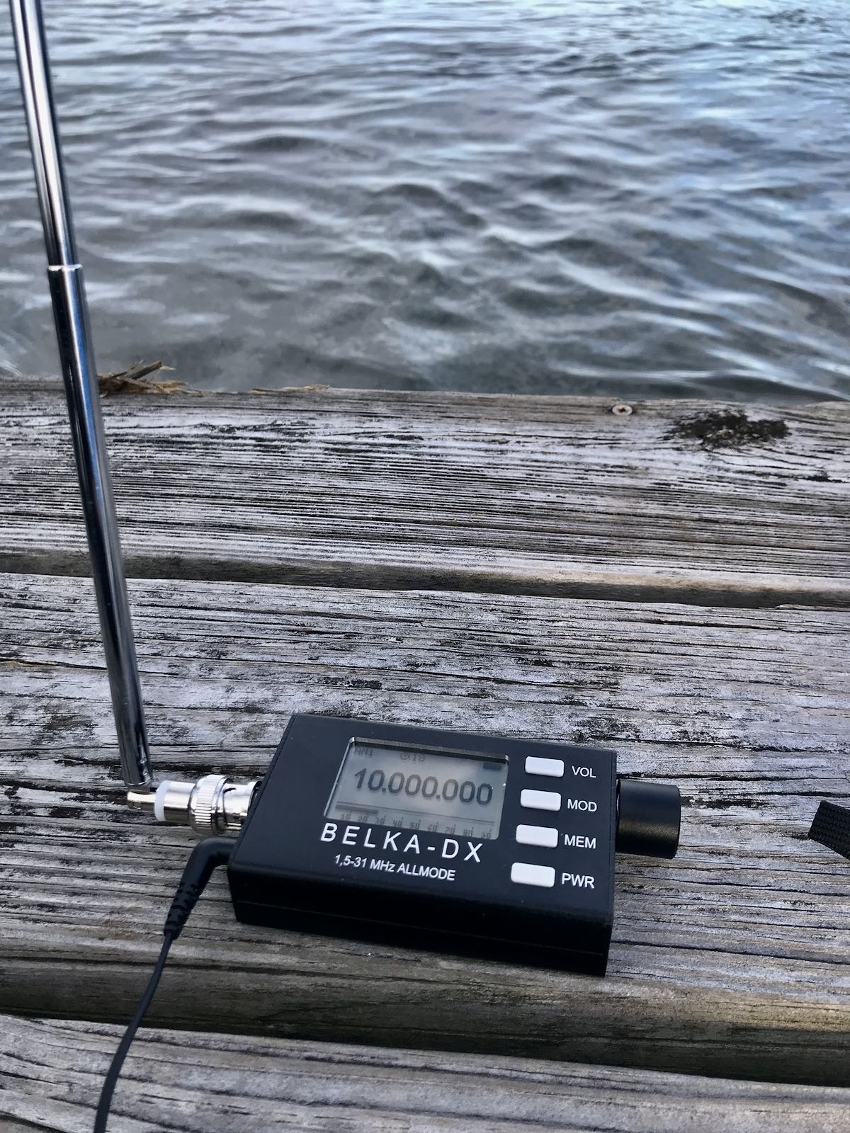
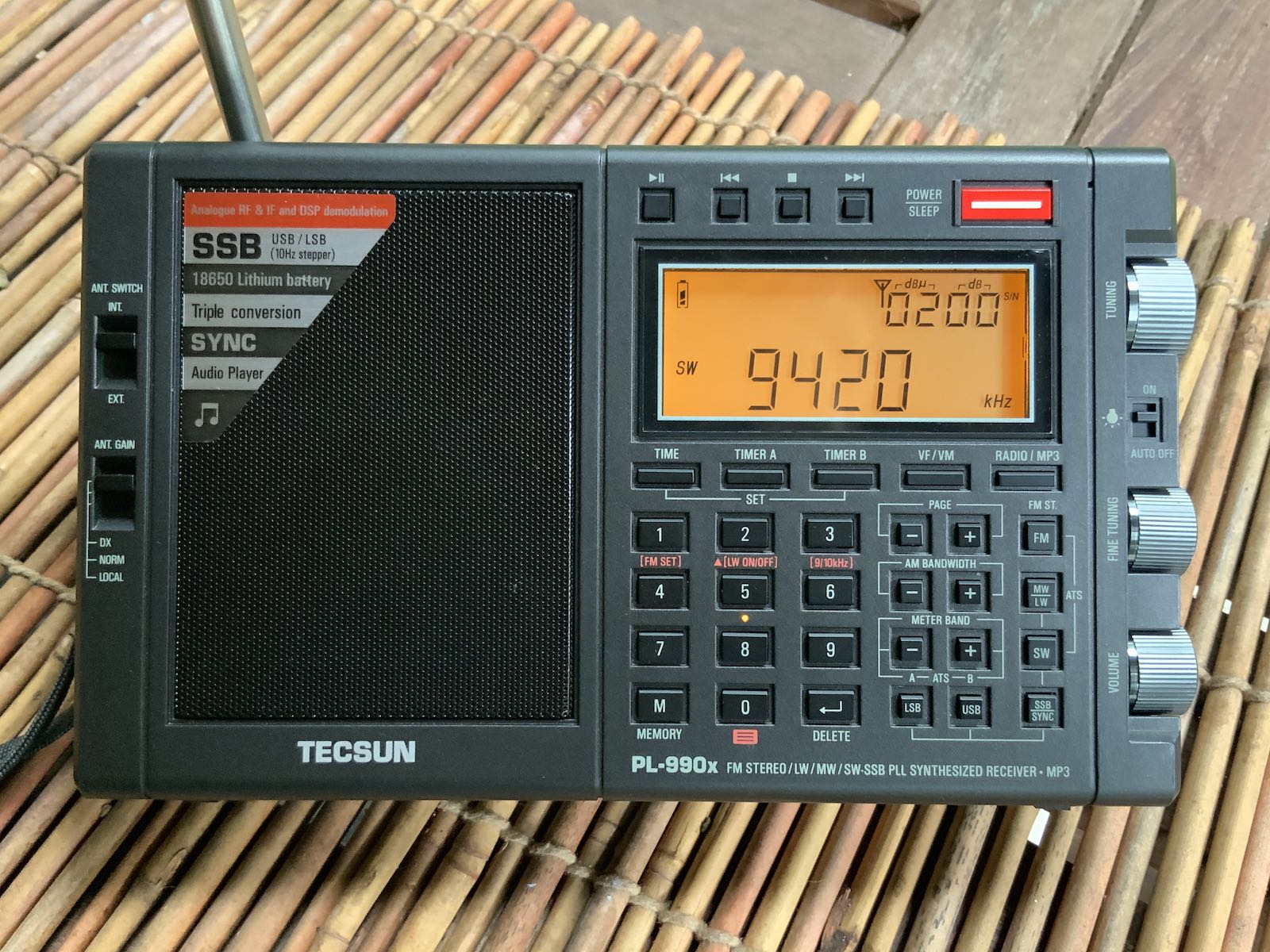
Portable shortwave receivers
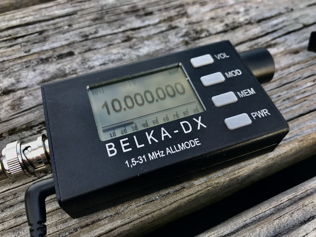
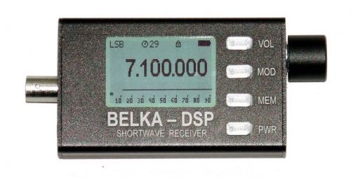
Since they’re new to the market, both the Tecsun PL-990 (above) and Belka DX (below) got a lot of air time.
I do like both radios and even took the pair on vacation recently even though packing space was very limited. I see the Belka DX getting much more air time in the future because 1.) it’s a performer (golly–just check out 13dka’s review of the Belka DSP) and 2.) it’s incredibly compact. The Belka now lives in my EDC bag, so is with me for impromptu listening and DXing sessions.
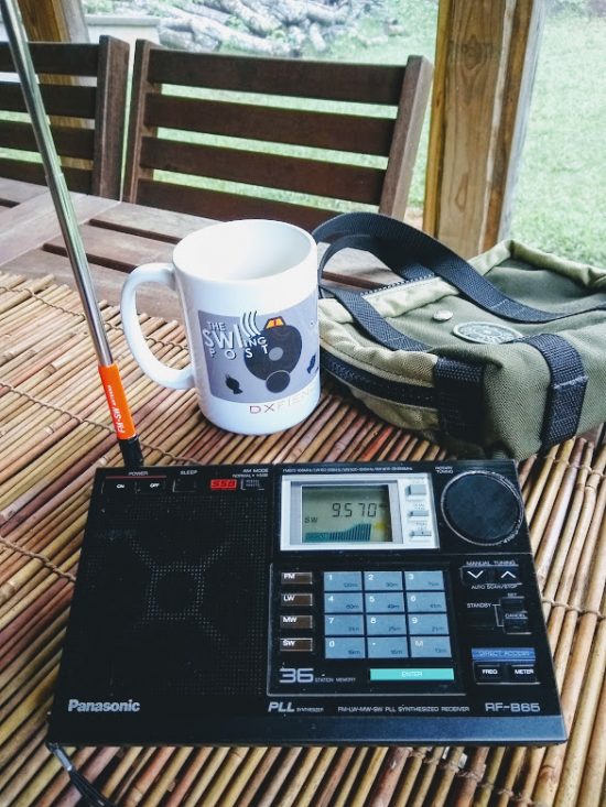
A classic solid-state portable that also got a lot of air time this year was the Panasonic RF-B65. Not only is it a performer, but it has a “cool” factor that’s hard to describe. I love it.
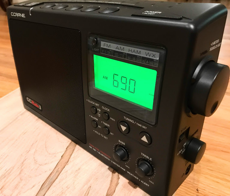
Tabletop portables
In a sense, the C.Crane CCradio3 got more play time than any of my radios. It sits in a corner of our living area where we tune to FM, AM and weather radio–90% of the time, though, it’s either in AUX mode playing audio piped from my SiriusXM receiver, or in Bluetooth mode playing from one of our phones, tables, or computers. In October, the prototype CCRadio Solar took over SiriusXM duty brilliantly. I’m guessing the CCRadio3 has easily logged 1,600 hours of play time this year.
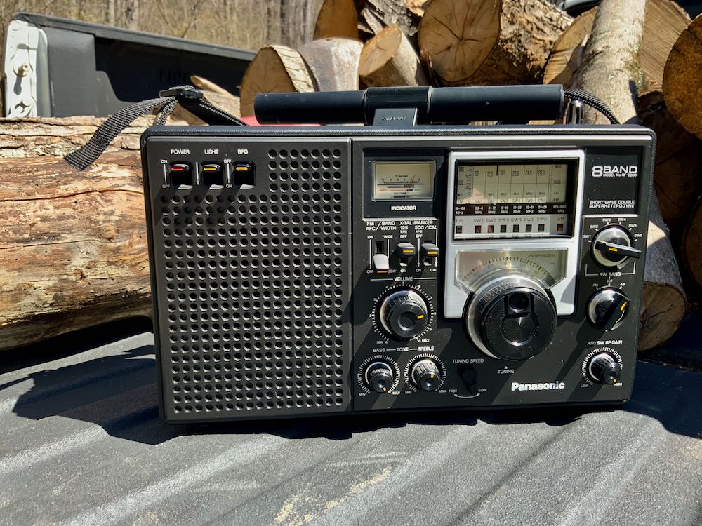
Of course, the Panasonic RF-2200 is one of my all-time favorite vintage solid-state portables, so it got a significant amount of field time.
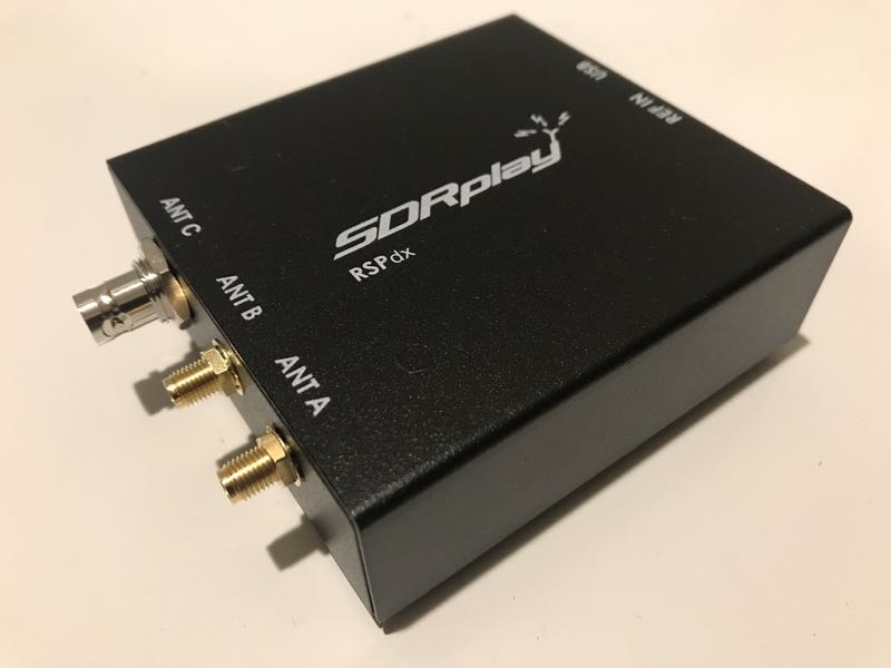
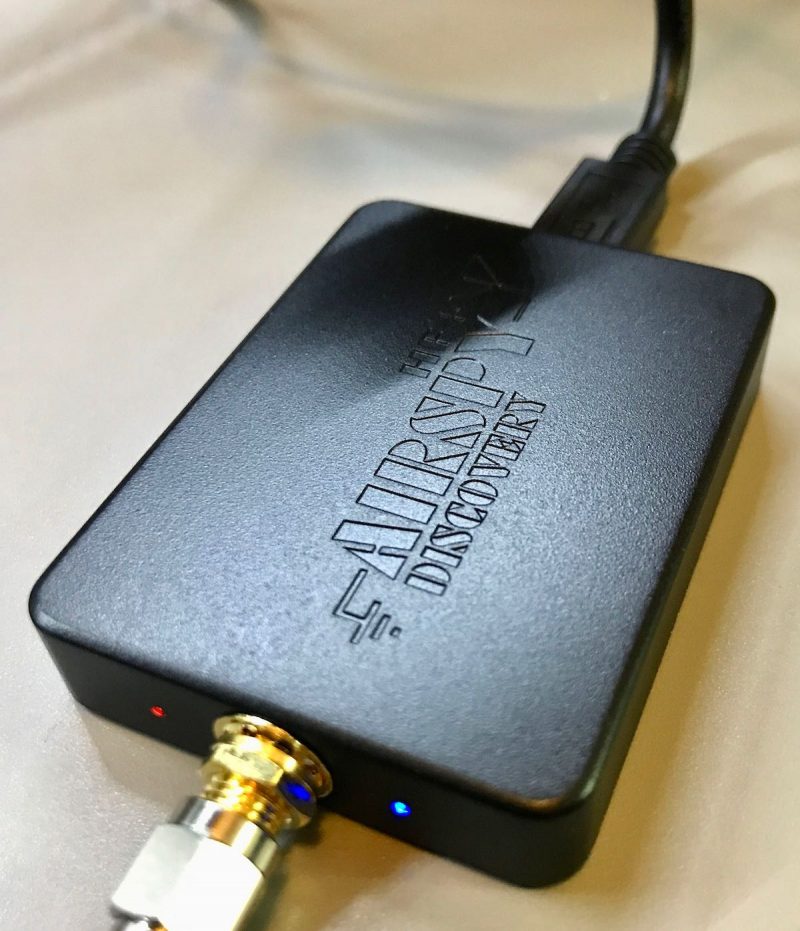
The HF+ Discovery was my choice receiver for portable SDR DXing and the RSPdx when I wanted make wide bandwidth recordings and venture above VHF frequencies.
Home transceivers
Without a doubt the new Mission RGO One 50 watt HF transceiver got the most air time at home and a great deal of field time as well. It’s such a pleasure to use and is a proper performer to boot!
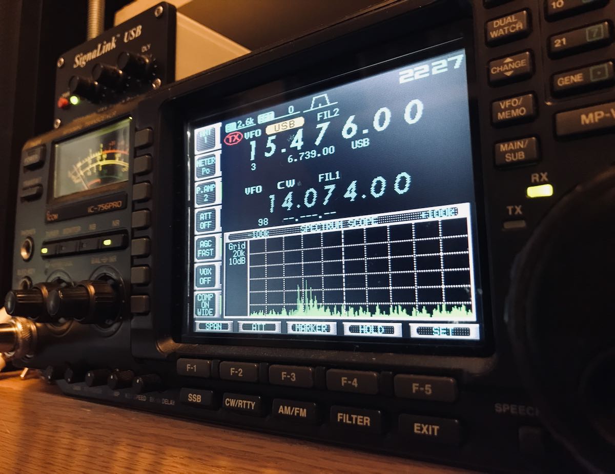
My new-to-me Icom IC-756 Pro, however, has become my always-connected, always-ready-to-pounce home 100W HF transceiver. It now lives above my computer monitor, so within easy reach. Although it’s capable of 100+ watts out, I rarely take it above 10 watts. The 756 Pro has helped me log hundreds of POTA parks and with it, I snagged a “Clean Sweep” and both bonus stations during the annual 13 Colonies event.
Field transceivers
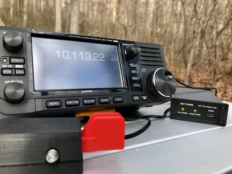
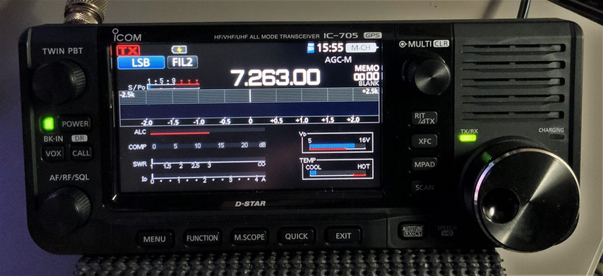
The new Icom IC-705 has become one of my favorite portable transceivers. Not only is it the most full-featured transceiver I’ve ever owned, but it’s also a brillant SWLing broadcast receiver. With built-in audio recording, it’s a fabulous field radio.
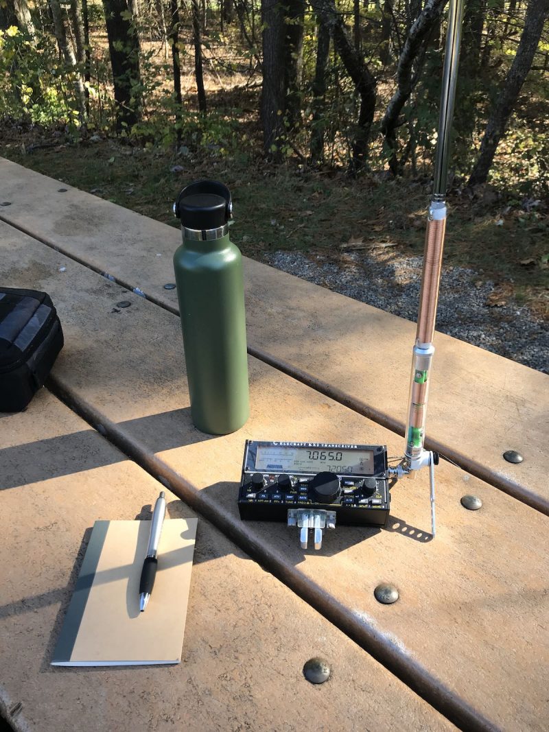
Still, the Elecraft KX2 remains my choice field radio for its portability, versatility and incredibly compact size. This year, in particular, I’ve had a blast pairing the KX2 with the super-portable Elecraft AX1 antenna for quick field activations. I’ve posted a few field reports on QRPer.com and also a real-time video of an impromptu POTA activation with this combo:
How about you?
What radios did use use the most this year and why? Did you purchase a new radio this year? Have you ventured into the closet, dusted off a vintage radio and put it on the air?
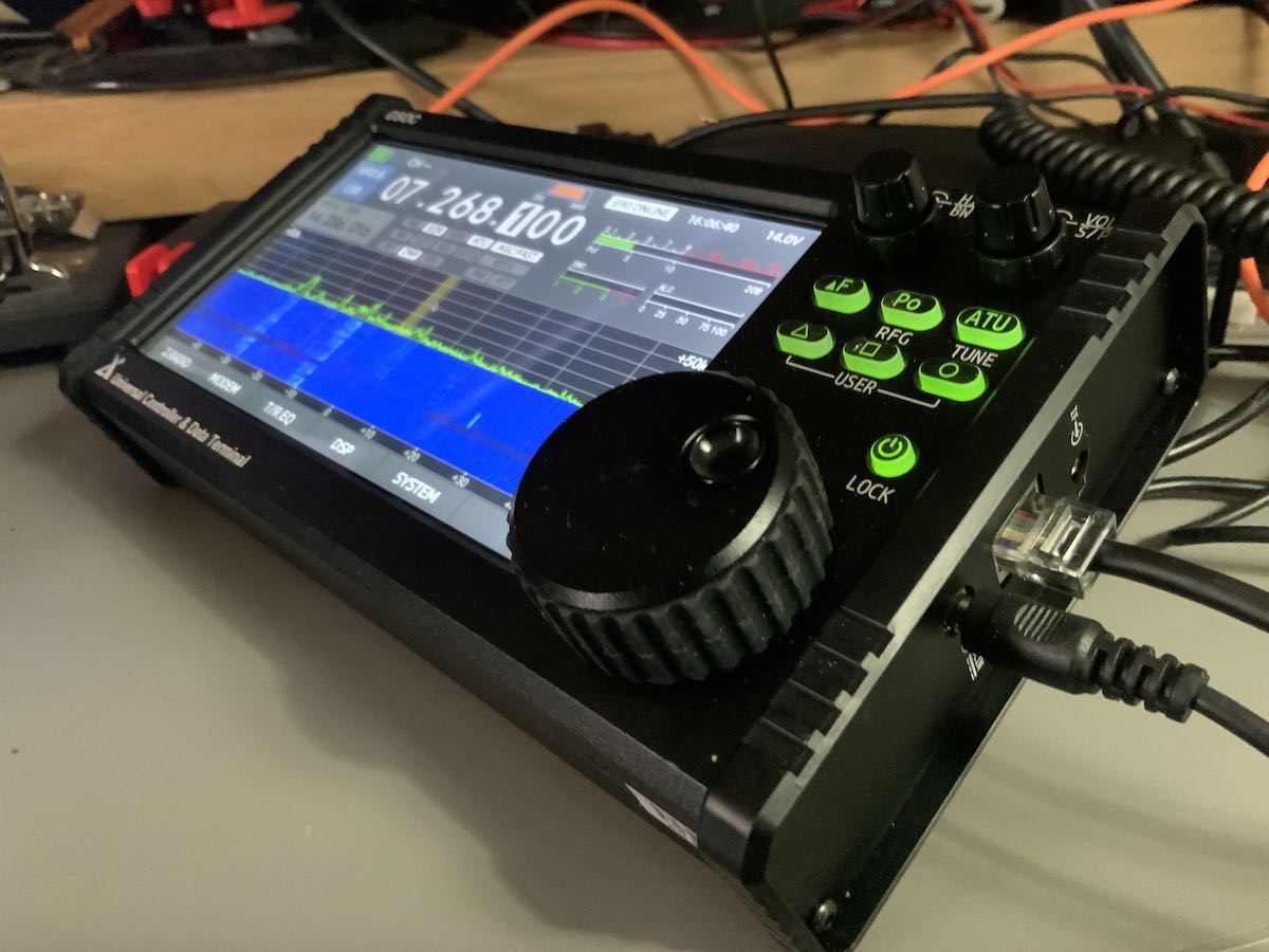
For those of you who have been asking about the new Xiegu GSOC controller, I just updated my unit with the latest firmware (version 1.1).
Firmware notes show that it addresses the following items:
Xiegu GSOC FW V1.1
1. Solved the CW sidetone delay problem
2. Solved the problem of unstable system and occasional crash
3. Added RTTY modem
4. Added CW decoder
5. Added SWR scanner
6. Added FFT/Waterfall level adjustment
7. Added FFT line/fill color mixer
The list above was copied directly from the version notes.
I’m currently evaluating the GSOC/G90 pair which were kindly sent to me on loan by Radioddity. I upgraded the GSOC firmware to v1.1 this weekend.
What follows are some of my evaluation notes an observations after performing the upgrade.
Updating firmware
Updating the GSOC firmware is a pretty straight-forward process.
First you must download the GSOC firmware package (about 330 MB!) which includes a disk image and application to flash the image to a MicroSD card.
Yes, you’ll need a dedicated MicroSD card to upgrade the GSOC firmware–meaning, you can’t simply use a MicroSD card with data on it you’d like to keep because the process of flashing the ISO file also includes a full format with multiple partitions.
You’ll also need an SD Card reader/writer if your Windows PC doesn’t include one.
The included firmware application/tool makes it quite easy to flash a disk image on the MicroSD card.
After the MicroSD card has been prepared, simply turn off the GSOC, insert the MicroSD card on the left side of the GSOC, turn it back on and the GSOC will automatically boot from the MicroSD card and install the new OS/firmware.
Once the upgrade has completed, the GSOC will turn itself off and you must remove the MicroSD card.
If you want to restore the MicroSD card to one partition, you’ll need to perform another format and shrink the volumes.
CW sidetone latency (still issues)
After performing the upgrade, I hopped on the air and tried to make a few CW contacts since I noted in the version notes that the CW sidetone latency had been addressed. So far, my evaluation has pretty much been on hold because I’m unable to use CW mode with any sense of sending accuracy.
Unfortunately, I’m still finding that there’s still a bit of sidetone latency or keyer timing interfering with my ability to correctly send words and letters.
To my ear, it sounds like there’s much less latency in the sidetone audio now (compared with v1.0 which was a little insane) but I still struggle sending characters that end in a string of dits or dashes. For example, when I try to send a “D” the radio will often produce a “B” by adding one extra dit. Or if I try to send a “W” it might produce a “J”. I know something is a little bit off because I botched up two CW contacts with POTA stations yesterday as I tried to send my own callsign correctly. And “73” was even problematic.
I’m guessing that there may still be a bit of audio lag between the G90 body (where the CW key is plugged in) and the GSOC (where the sidetone audio comes out). At the end of the day, the keying information must be sent to the GSOC from the G90 transceiver body and I assume the processor on the G90 is causing a bit of audio latency. Hopefully, Xiegu can sort this out. It’s a serious issue for anyone who wants to operate CW with the GSOC.
If you own the GSOC and operate CW, I’d love your comments and feedback.
Other updates
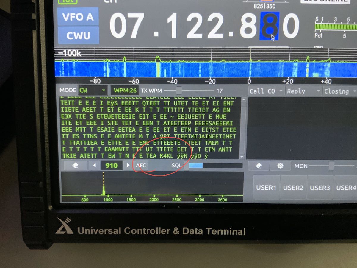
I tried using the CW decoder yesterday via the “Modem” menu and had limited success decoding a CW rag chew.
My markup in red: You can see at the very end of this conversation, it decoded the call sign, but interpreted “TU” as “TEA”
The decoder seemed to adjust the WPM rate automatically at one point, but as you can see in the image above, almost every dit was interpreted as an “E” and every dash a “T”. I must assume I don’t have it configured properly, but I don’t have an operator’s manual for reference and instruction. I’ve also tried RTTY decoding, but haven’t been successful so far–I’m pretty sure this is also because I haven’t configured it properly.
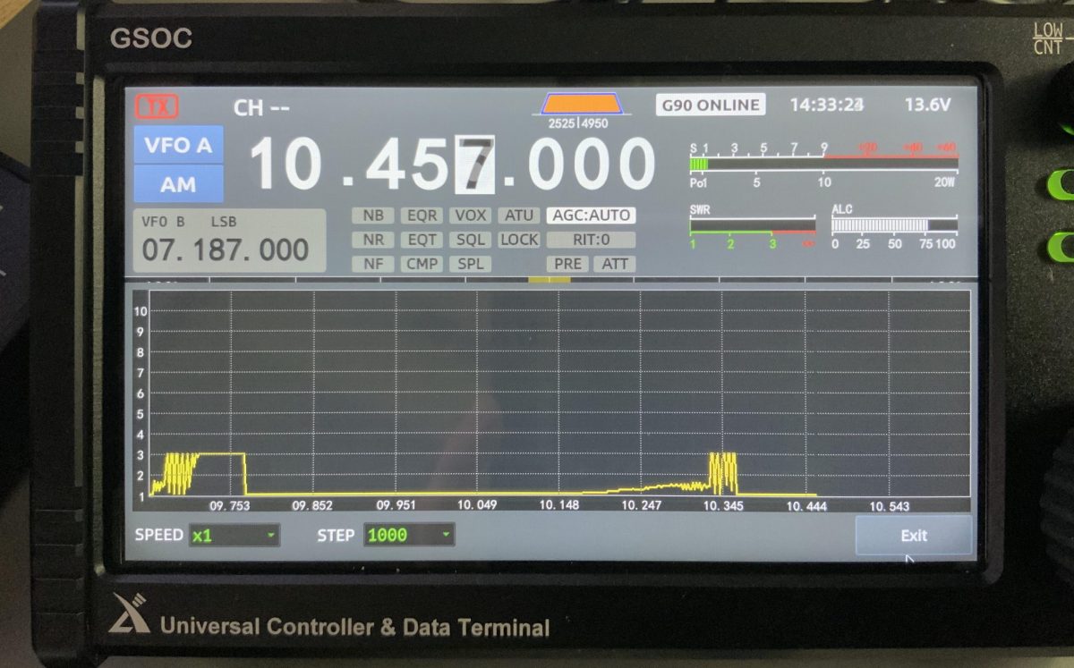
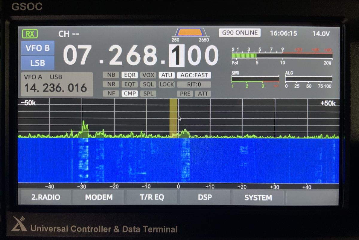
SWR Scanner
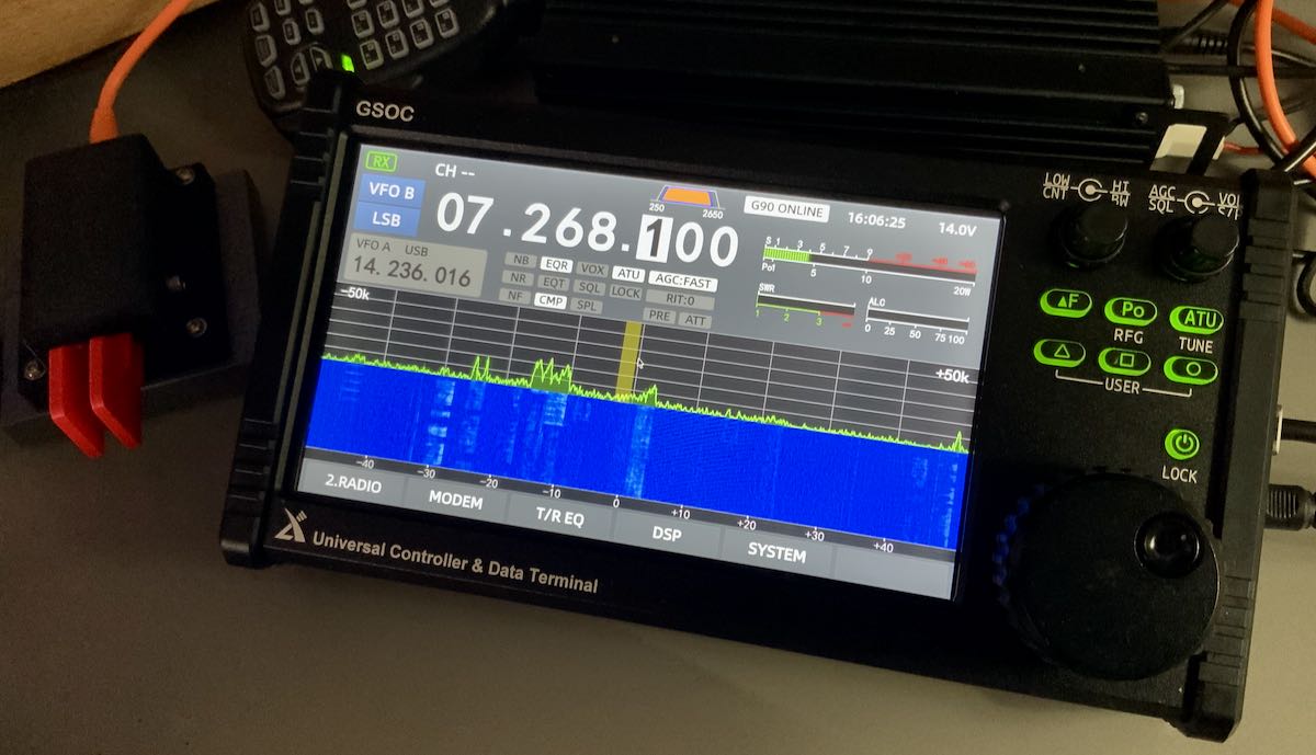
I tested the new SWR scanner and it seems to work quite well, plotting SWR across a given frequency range. I did note, however, that it doesn’t seem to confine itself to the ham bands at all. It does inject a signal as it scans (I read 1.5 to 2 watts on my CN-801 meter).
I discovered out-of-band scanning when I took the photo above while trying to do a scan of the 30 meter band. It started around 9.6 MHz–well into the 31M broadcast band where it shouldn’t be transmitting. Xiegu needs to limit transmitted signal to the ham bands.
Memory Keying
I had hoped Voice Memory Keying would be added along with TX/RX recording. I do believe this will eventually be included in a future update. It appears via the “Modem” menu that CW Memory Keying has been added, but I can’t sort out how to make it work (again, a operation manual would be quite handy).
Audio recording
I had hoped transmit and received audio recording would be added in this firmware update; I understand this will eventually be added.
Combined current drain
As I mentioned in a previous GSOC update, the GSOC controller and G90 transceiver both need a 12V power source–indeed, each has a dedicated power port. The GSOC does not derive power from the G90.
I was originally told that the G90 and GSOC both pull about .60 amps in receive which would total 1.2 amps combined. My Hardened Power Systems QRP Ranger battery pack displays voltage and current; it’s not a lab-grade measurement device, but it’s pretty accurate. When I operate the GSOC and G90 at a moderate volume levels in receive, it appears to draw 0.95 to 0.97 amps–basically, 1 amp.
At home on a power supply, this is inconsequential, but in the field you’d need to keep this in mind when choosing a battery. It’s on par with a number of 100 watt transceivers.
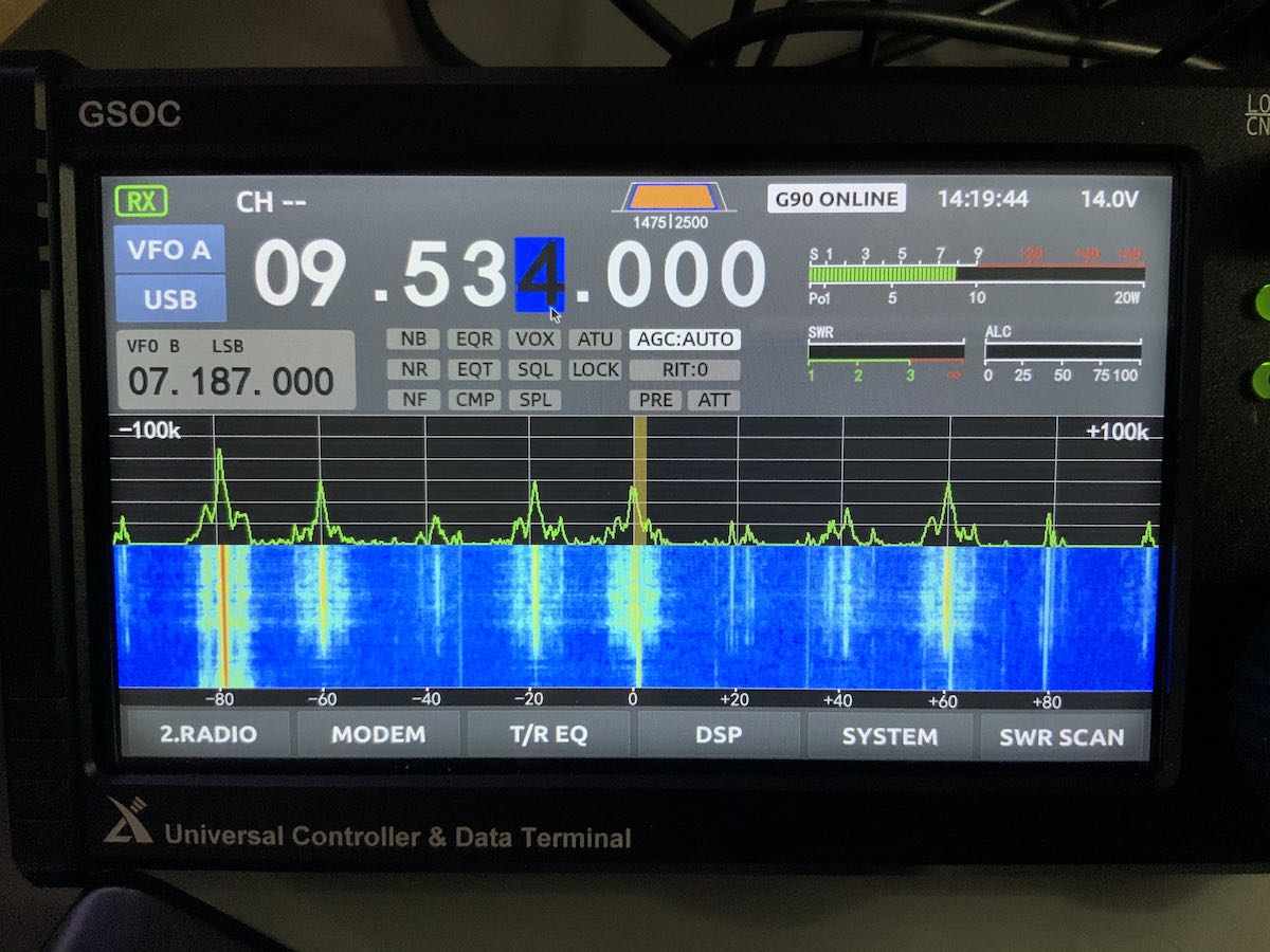
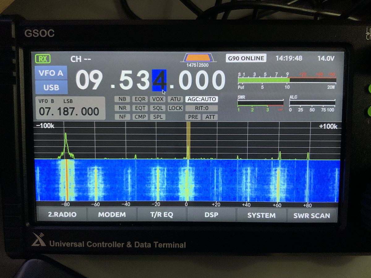
Spectrum display images
I’m still finding images on the GSOC display that are not present in the received audio. I mentioned this in my initial overview and it doesn’t seem the firmware update addressed this.
I can only assume the spectrum imaging might be due to the I/Q input being too “hot” coming from the G90 via the shielded audio patchcord. Perhaps there’s a function to manually lower the I/Q gain, but I haven’t found that yet.
Spectrum images are most noticeable on the 31 meter band, but found them on the 20 meter ham band as well.
Here are two screen shots that show how images appear when a nearby signal overwhelms the GSOC:
Images are not present all of the time, only when a strong signal intrudes.
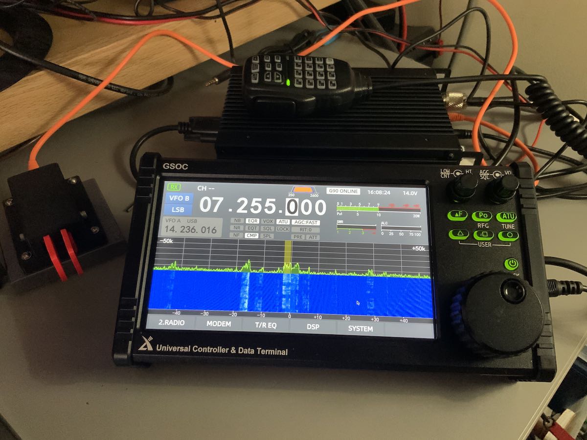
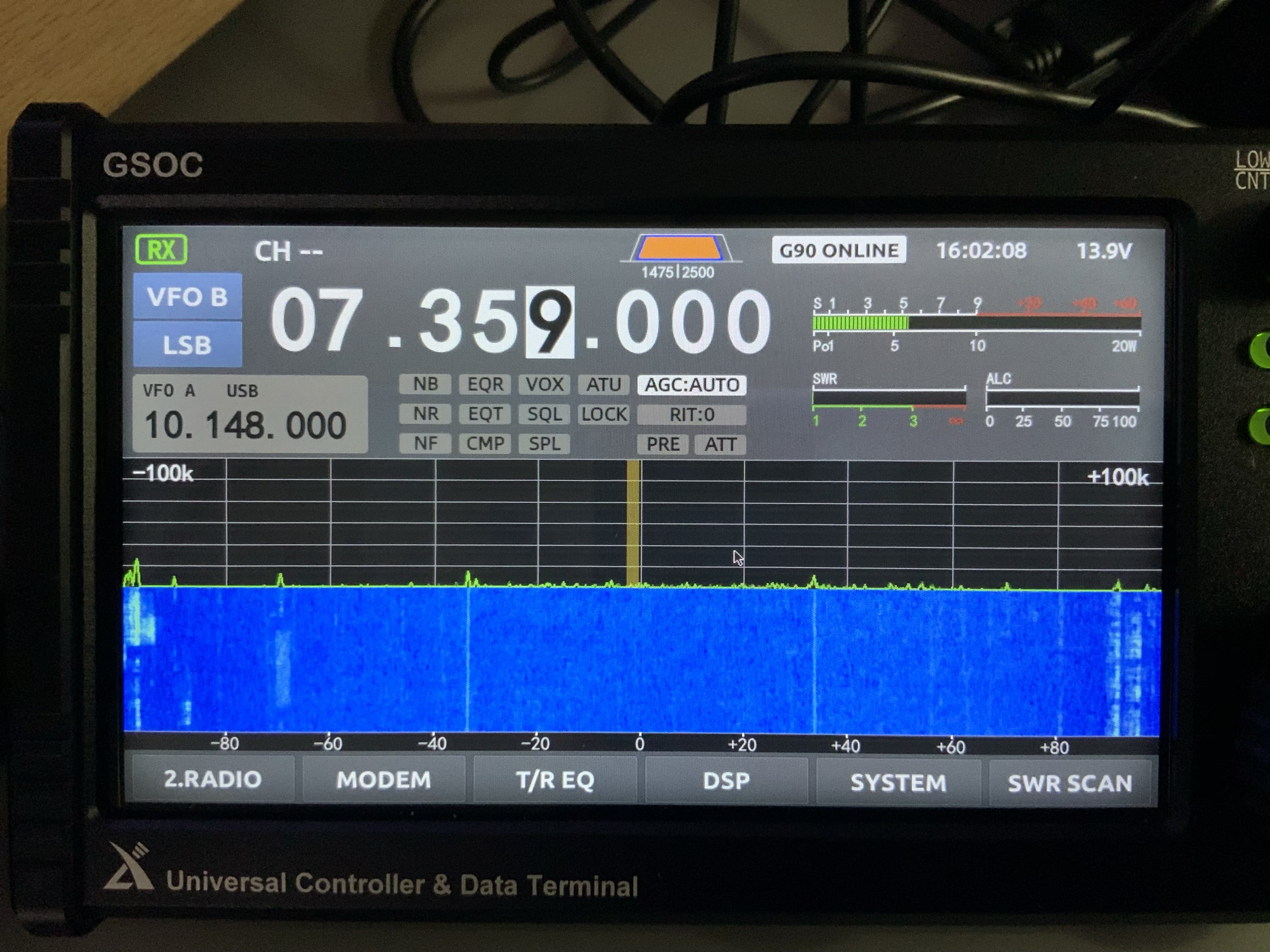
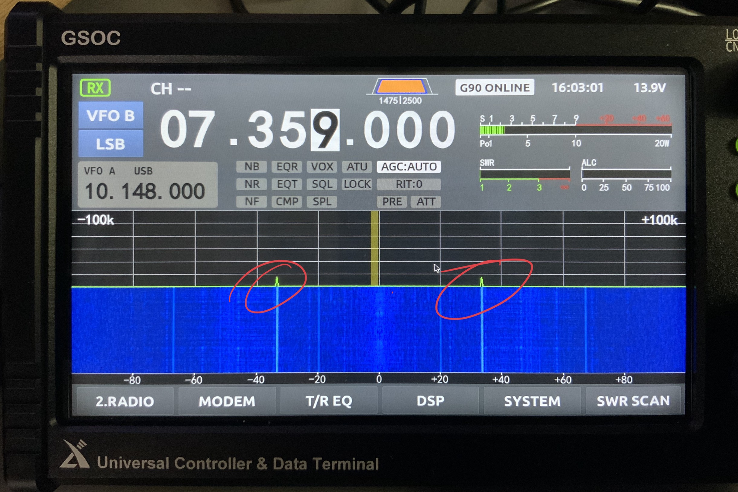
Ever-present noise and spurs in portions of spectrum
Perhaps this is related to the issue above, but there are some spurs on the spectrum display that seem to be present whether the G90/GSOC is hooked up to an antenna or dummy load.
Here’s a photo of the GSOC hooked up to an antenna:
And to a dummy load:
I’ve highlighted the spurs in red and as you can see, the intensity is stronger without an antenna thus I’m guessing this is internally-generated. The spurs do not move on the display as you change frequency.
Other notes
Again, I feel like the GSOC firmware isn’t mature and I can’t yet recommend purchasing it. I feel like Xiegu have rushed this unit to market.
I know that, over time, more features will be added and Xiegu certainly has a track record of following up.
When I evaluate a product, I keep a list of notes that I send to the manufacturer and to keep for my own reference. In Alpha and/or Beta testing, I’d share this info only with the manufacturer. Since the GSOC is a product that’s in production and widely available, however, I thought I’d share them here publicly:
GSOC volume control scale is 0 to 28. The difference between 0 (muted) to 1 seems to be the biggest increment. Volume 1 is actually a low to moderate volume level (i.e. a bit high).
Boot up time for the GSOC is 30 seconds
A keyboard and mouse or capacitive stylus are almost required for accurate operation. Many of the touch screen buttons are quite small and difficult to accurately engage with fingertip. The pointer seems to fall slightly below where fingertip makes contact on the screen.
Notch Filter seems to have no effect even after the v1.1 upgrade. There is no Auto Notch feature either.
I can’t seem to engage split operation even though there are A/B switchable VFOs and a “Split” button above the spectrum display. Using a keyboard and mouse doesn’t engage it either.
There are a number of announced features that I haven’t discovered including some WiFi and Bluetooth wireless functionality.
For field use, you must pack quite a bit of kit: the transceiver, the controller, CW key cable, microphone, serial cable, I/Q cable, G90 Power cable, and GSOC power cable. It would also be advisable to take a wireless keyboard and mouse especially if you plan to use any advanced functions like CW memory keying.
It doesn’t appear that you have CAT control of the GSOC which complicates digital operation. I believe many of us hoped the GSOC would make digital mode operation easier with the G90, but it hasn’t. Indeed, I assumed the GSOC would have an internal sound card for digi modes much like the Icom IC-7300 and IC-705. Use of VOX control is still the best way to control transmit. I hope this can be upgraded else this would be a missed opportunity.
Since the v1.1 upgrade, the GSOC hasn’t crashed (it did frequently with the v1.0 firmware).
Not a pro or con, but I wish the AF Gain/Squelch was AF Gain/RF Gain like most HF transceivers. I’ve accidently engaged squelch twice which essentially muted audio. Pressing and holding the PO (Power Output) button opens the RG Gain control function).
The GSOC Universal Controller is an interesting accessory for the G90 and I’ve read comments from users that love the interface and added functionality.
If I’m being honest, I feel like I’m Beta testing the GSOC. I’ve yet to find a GSOC operation manual–this makes it very difficult to know if one has correctly configured the controller and engaged features/functions correctly. A quick start guide is included with the product, but it really only helps with connections and starting up the GSOC the first time. If you’re a GSOC early adopter, just be aware of this. Again, I’m pretty confident Xiegu will make refinements and include promised features in future firmware updates. I understand their software engineer closely monitors the GSOC discussion group as well. If you’re considering the purchase of a GSOC, I’d encourage you to join the GSOC group.
Questions? Comments?
As I said, I can’t recommend purchasing the GSOC controller yet. So much can change with firmware updates, however, I would encourage you to bookmark the tag GSOC to follow our updates here on the SWLing Post. I will update the GSOC controller each time a new firmware version is issued and until Radioddity asks for the loaner units to be returned. Again, many thanks to Radioddity for making this GSOC and G90 evaluation possible.
Feel free to comment with any questions you might have and I’ll do my best to answer them!
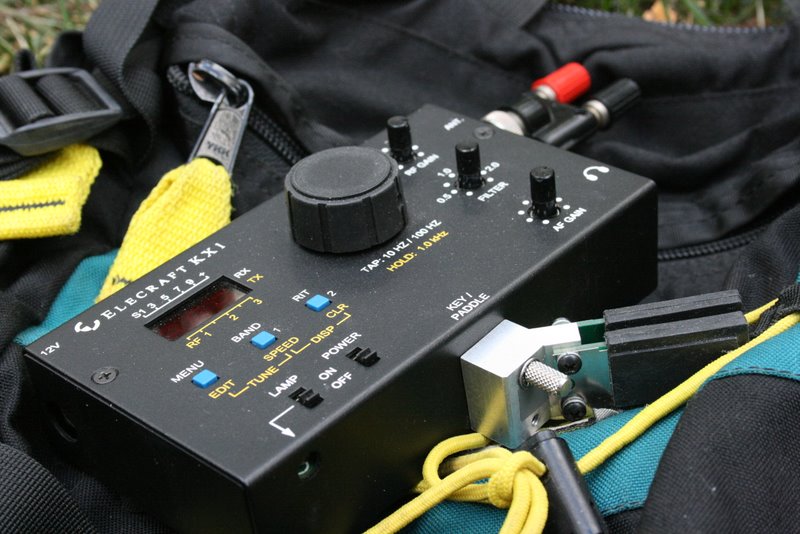
The seller, who lives about 2 hours from my QTH, described his KX1 as the full package: a complete 3 band (40/30/20M) KX1 with all of the items needed to get on the air (save batteries) in a Pelican 1060 Micro Case.
The KX1 I owned in the past was a four bander (80/40/30/20M) and I already double checked to make sure Elecraft still had a few of their 80/30 module kits available (they do!). I do operate 80M in the field on occasion, but I really wanted the 80/30 module to get full use of the expanded HF receiver range which allows me to zero-beat broadcast stations and do a little SWLing while in the field.
The seller shipped the radio that same afternoon and I purchased it for $300 (plus shipping) based purely on his good word.
The KX1 package
I’ll admit, I was a bit nervous: I hadn’t asked all of the typical questions about dents/dings, if it smelled of cigarette smoke, and hadn’t even asked for photos. I just had a feeling it would all be good (but please, never follow my example here–I was drunk with excitement).
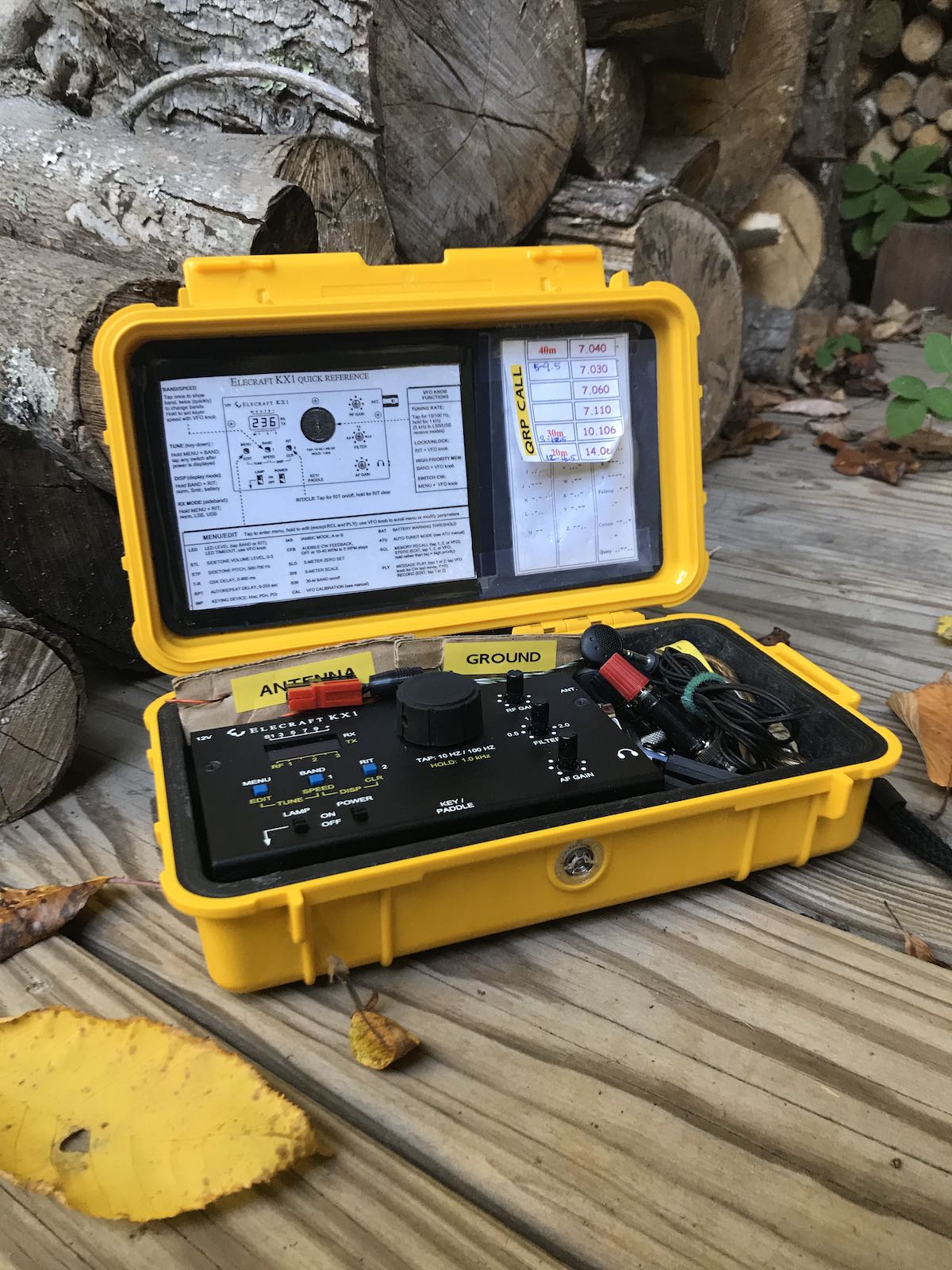
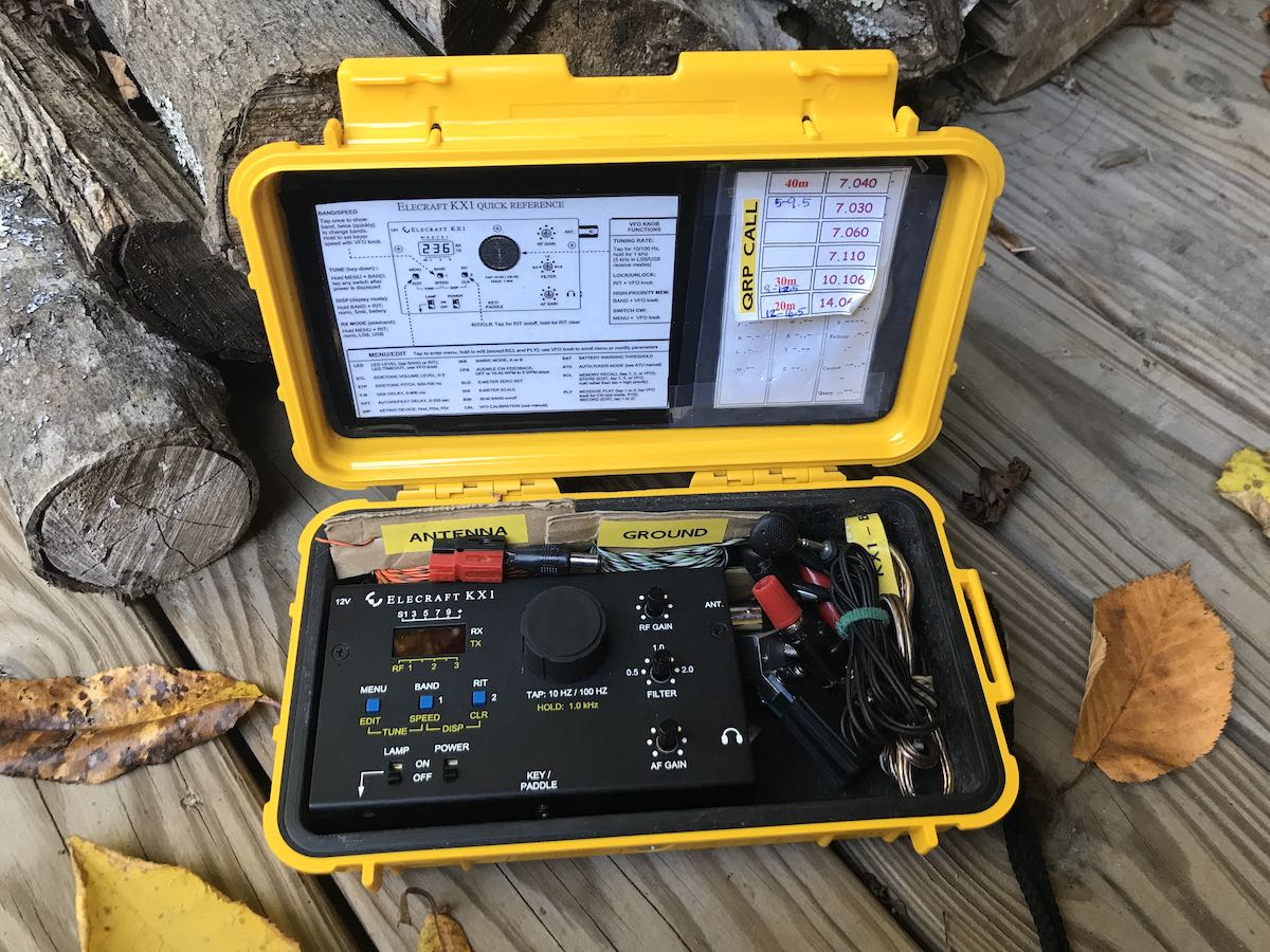
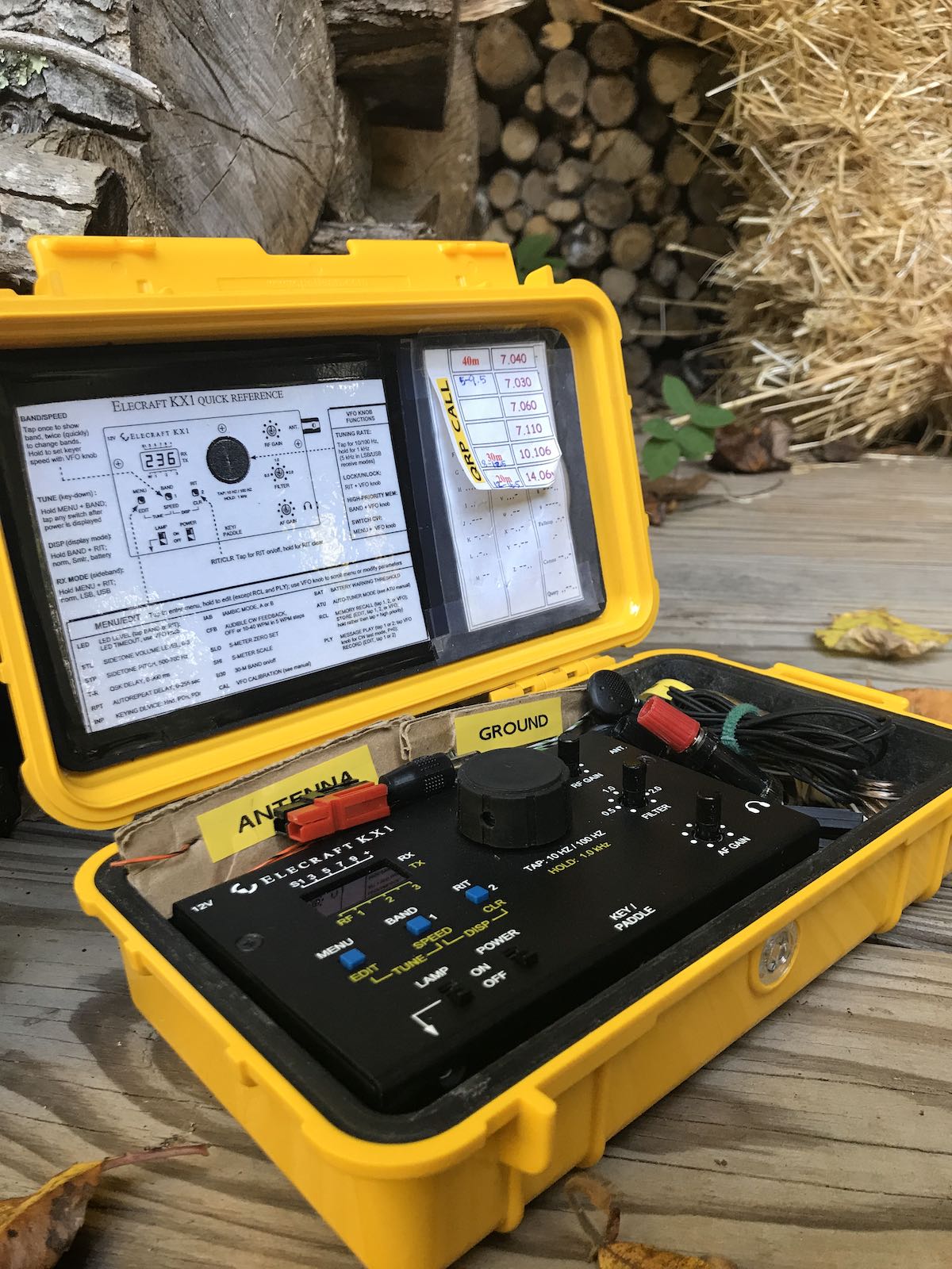
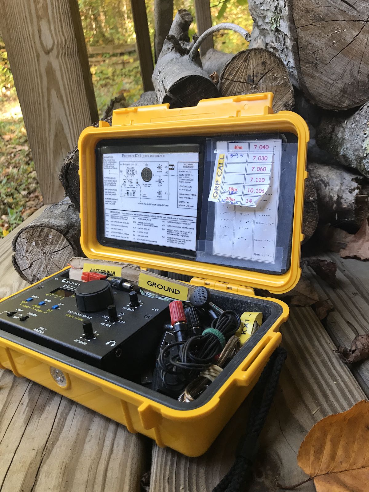
Here’s the photo I took after removing the Pelican case from the shipping box and opening it for the first time:
My jaw dropped.
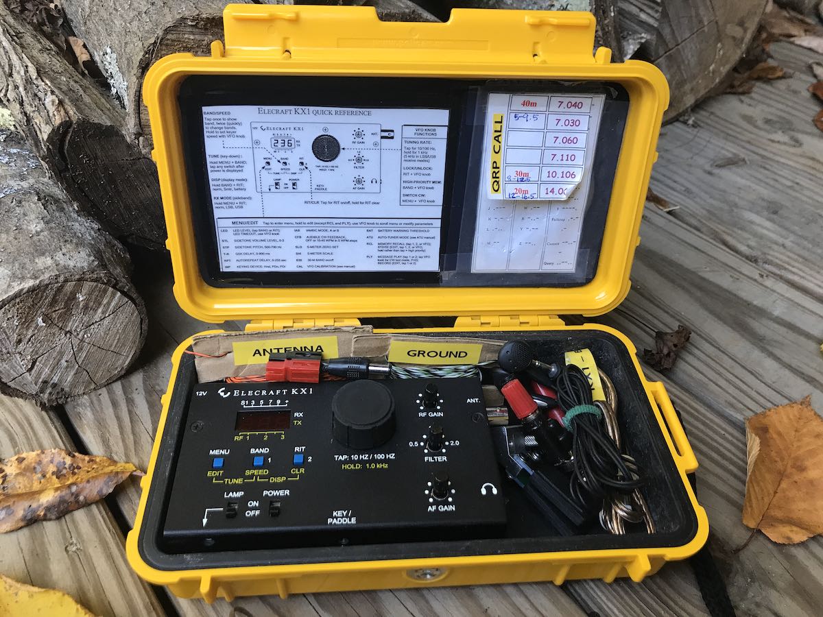
The seller was right: everything I needed (and more!) was in the Pelican case with the KX1. Not only that, everything was labeled. An indication that the previous owner took pride in this little radio.
I don’t think the seller actually put this kit together. He bought it this way two years ago and I don’t think he ever even put it on the air based on his note to me. He sold the KX1 because he wasn’t using it.
I don’t know who the original owner was, but they did a fabulous job not only putting this field kit together, but also soldering/building the KX1. I hope the original owner reads this article sometime and steps forward.
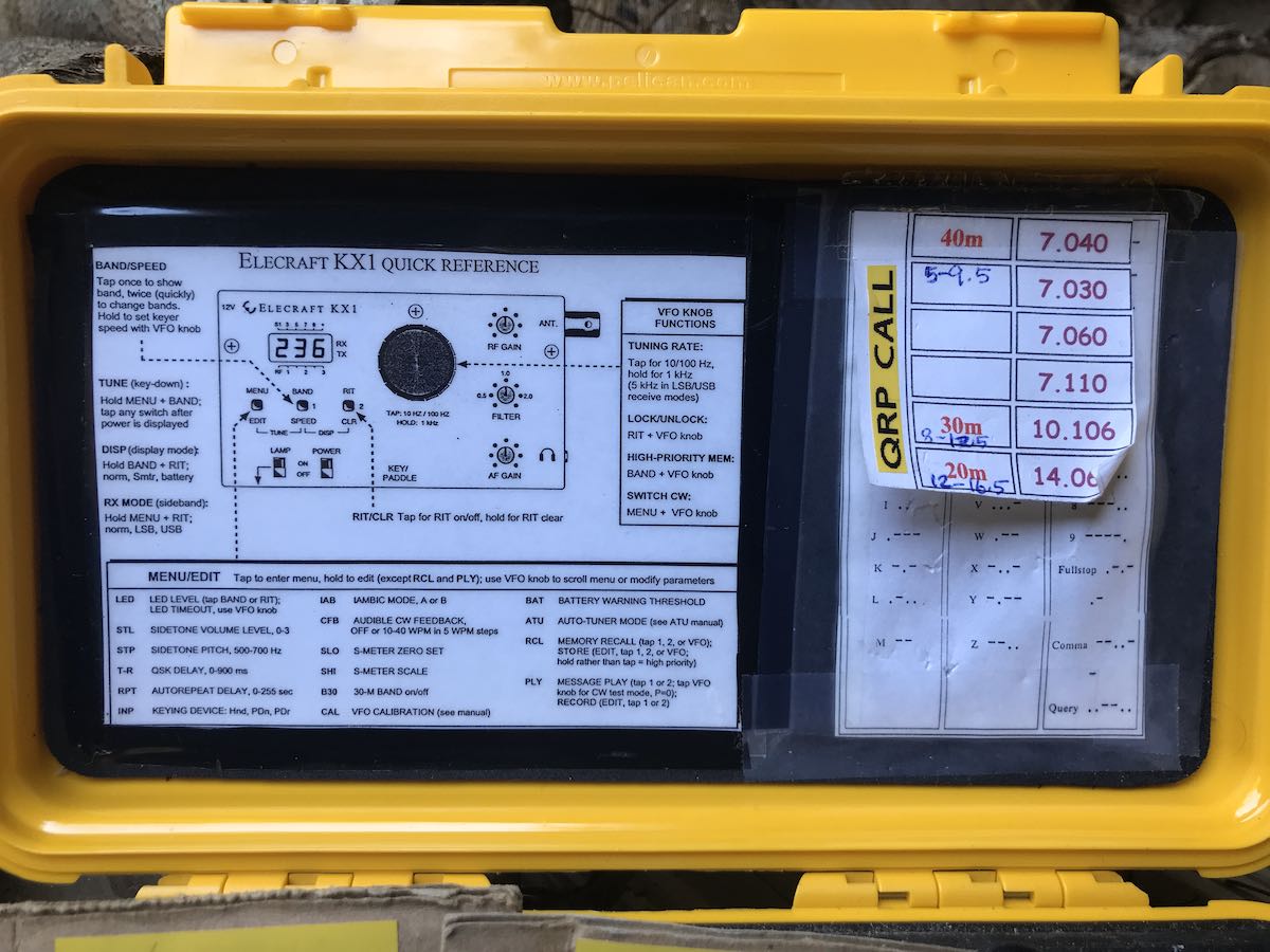
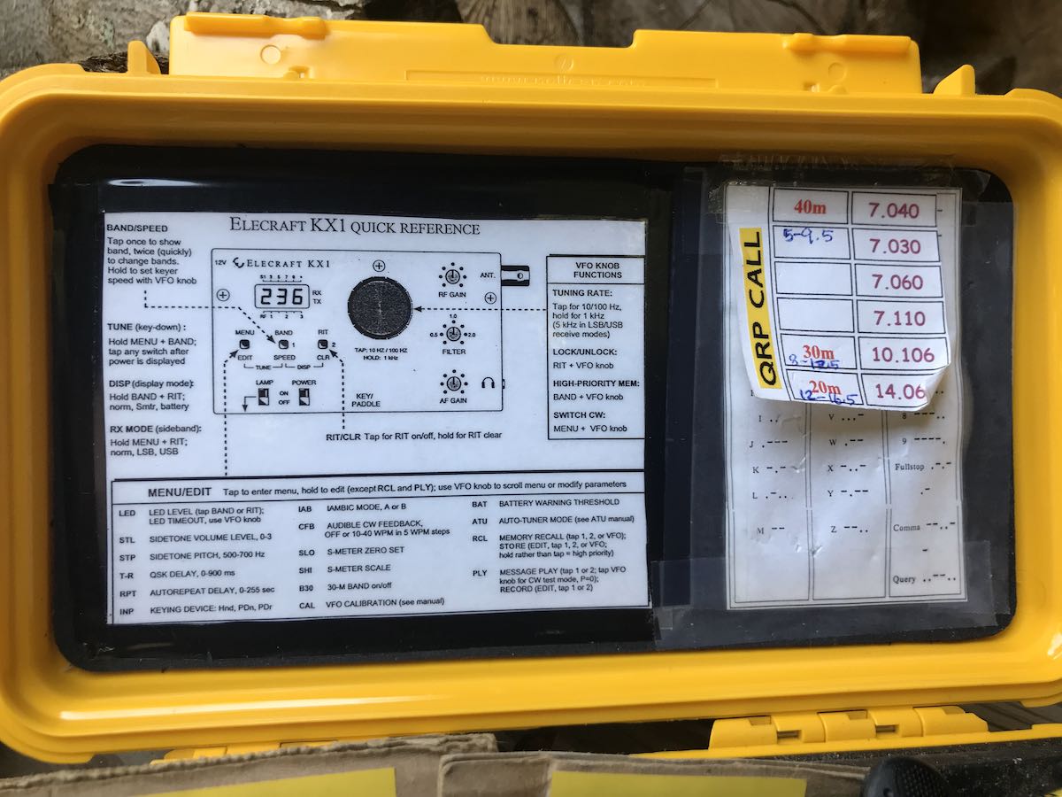
You might note in the photo that there’s even a quick reference sheet, Morse Code reference sheet and QRP calling frequencies list attached to the Pelican’s lid inside. How clever!
I plan to replace the Morse Code sheet with a list of POTA and SOTA park/summit references and re-print the QRP calling frequencies sheet. But other than that, I’m leaving it all as-is. This might be the only time I’ve ever purchased a “package” transceiver and not modified it in some significant way.
Speaking of modifying: that 80/30 meter module? Glad I didn’t purchase one.
After putting the KX1 on a dummy load, I checked each band for output power. Band changes are made on the KX1 by pressing the “Band” button which cycles through the bands one-way. It started on 40 meters, then on to 30 meters, and 20 meters. All tested fine. Then I pressed the band button to return to 40 meters and the KX1 dived down to the 80 meter band!
Turns out, this is a four band KX1! Woo hoo! That saved me from having to purchase the $90 30/80M kit (although admittedly, I was looking forward to building it).
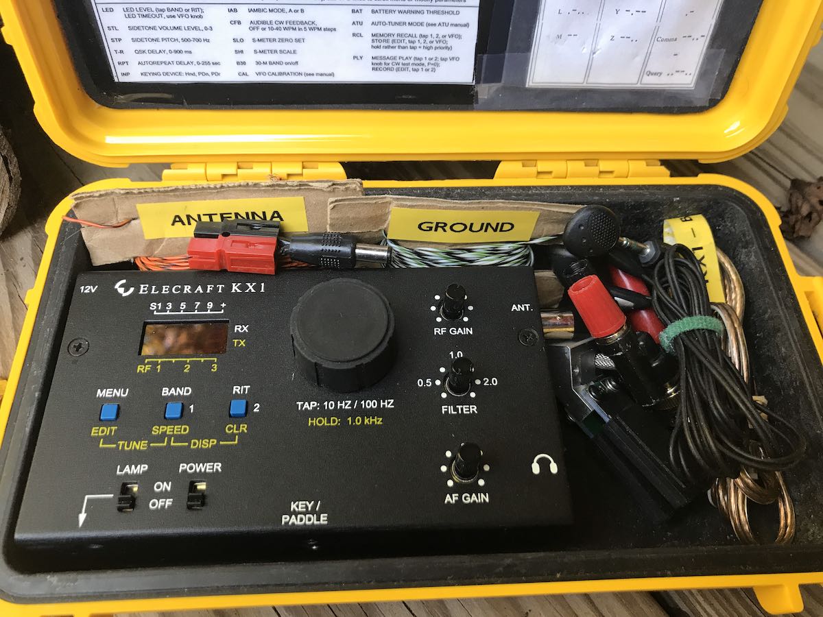
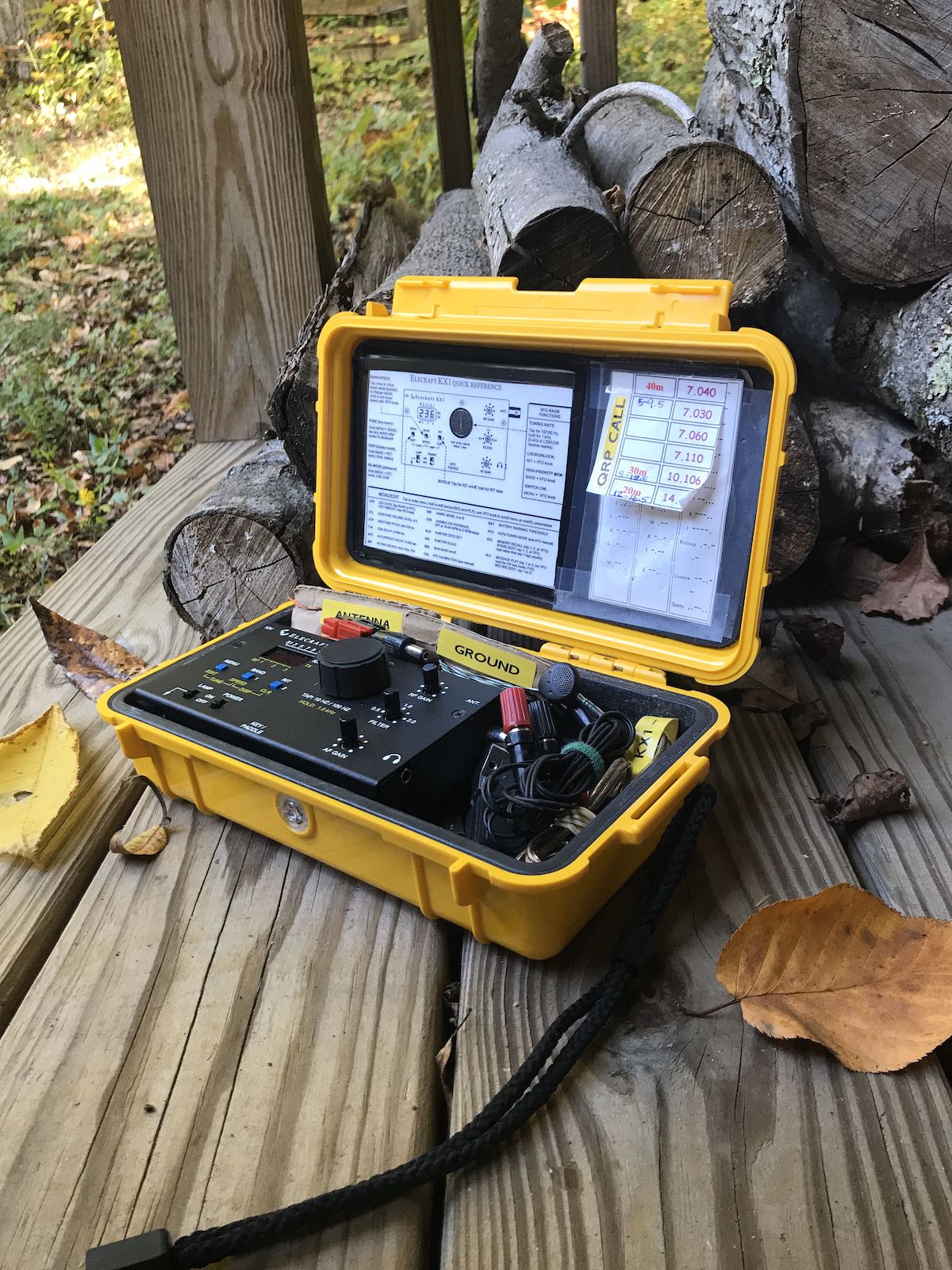
Photos
The only issue with the KX1 was that its paddles would only send “dit dah” from either side. I was able to fix this, though, by disassembling the paddles and fixing a short.
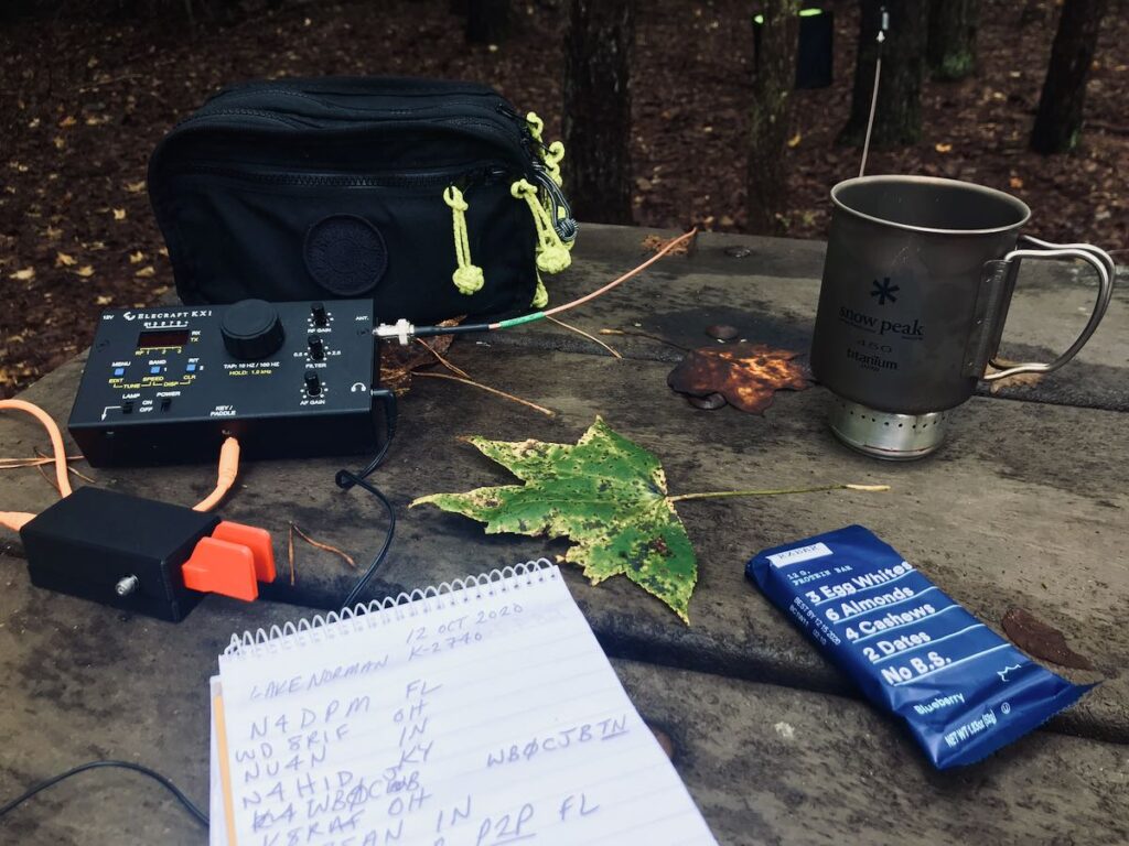
Although I’m currently in the process of testing the Icom IC-705, I’ve taken the KX1 along on a number of my park adventures and switched it out during band changes.
Indeed, my first two contacts were made using some nearly-depleted AA rechargeables on 30 meters: I worked a station in Iowa and one in Kansas with perhaps 1.5 watts of output power–not bad from North Carolina!
I’m super pleased to have the KX1 back in my field radio arsenal.
I name radios I plan to keep for the long-haul, so I dubbed this little KX1 “Ruby” after one of my favorite actresses, Barbara Stanwyck.
Look for Ruby and me on the air at a park or summit near you!
Before I had even taken delivery of the new Icom IC-705 transceiver, a number of SWLing Post readers asked me to do a series of blind audio comparison tests like I’ve done in the past (click here for an example).
Last week, I published a series of five audio tests/surveys and asked for your vote and comments. The survey response far exceeded anything I would have anticipated.
We received a total of 931 survey entries/votes which only highlights how much you enjoy this sort of receiver test.
In this challenge, I didn’t even give you the luxury of knowing the other radios I used in each comparison, so let’s take a look…
The competition
Since the Icom IC-705 is essentially a tabletop SDR, I compared it with a couple dedicated PC-connected SDRs.
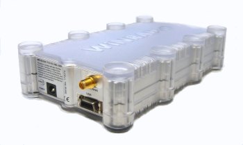
WinRadio Excalibur SDR
The WinRadio Excalibur
I consider the WinRadio Excalibur to be a benchmark sub $1000 HF, mediumwave, and longwave SDR.
It is still my staple receiver for making off-air audio and spectrum recordings, and is always hooked up to an antenna and ready to record.
In the tests where I employed the WinRadio Excalibur, I used its proprietary SDR application to directly make recordings. I used none of its advanced filters, AGC control, or synchronous detection.
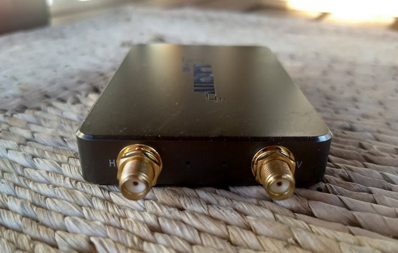
I also consider the Airspy HF+ SDR to be one of the finest sub-$200 HF SDRs on the market.
The HF+ is a choice SDR for DXing. Mine has not been modified in any way to increase its performance or sensitivity.
In the test where I employed the HF+ I used Airspy’s own SDR application, SDR#, to directly make recordings. I used none of its advanced filters, AGC control, noise reduction, or synchronous detection.
I thought it might be fun to include it in a comparison although, in truth, it’s hardly fair to compare a $160 receiver with a $1300 SDR transceiver.
The Belka, to me, is like a Lowe HF-150 in a tiny, pocket package.
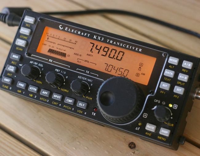
Elecraft KX3 QRP transceiver
The Elecraft KX3
The KX3 is one of the best transceivers I’ve ever owned. Mine has the CW roofing filter installed (only recently) and is, without a doubt, a benchmark performer.
If you check out Rob Sherwood’s receiver test data table which is sorted by third-order dynamic range narrow spaced, you’ll see that the KX3 is one of the top performers on the list even when compared with radios many times its price. Due to my recording limitations (see below) the KX3 was the only other transceiver used in this comparison.
Herein lies a HUGE caveat:
The WinRadio application
As I’ve stated in SDR reviews in the past, it is incredibly difficult comparing anything with PC-connected SDRs because they can be configured on such a granular level.
When making a blind audio test with a stand-alone SDR radio like the IC-705–which has less configurability–you’re forced to take one of at least two paths:
Tweak the PC-connected SDR until you believe you’ve found the best possible reception audio scenario and use that configuration as a point of comparison, or
Attempt to keep the configuration as basic as possible, setting filters widths, AGC to be comparable and turning off all other optional enhancements (like synchronous detection, noise reduction, and advanced audio filtering to name a few).
I chose the latter path in this comparison which essentially undermines our PC-connected SDRs. Although flawed, I chose this approach to keep the comparison as simple as possible.
While the IC-705 has way more filter and audio adjustments than legacy transceivers, it only has a tiny fraction of those available to PC-connected SDRs. Indeed, the HF+ SDR, for example, can actually be used by multiple SDR applications, all with their own DSP and feature sets.
In short: don’t be fooled into thinking this is an apples-to-apples comparison. It is, at best, a decent attempt at giving future IC-705 owners a chance to hear how it compares in real-word live signals.
Recordings
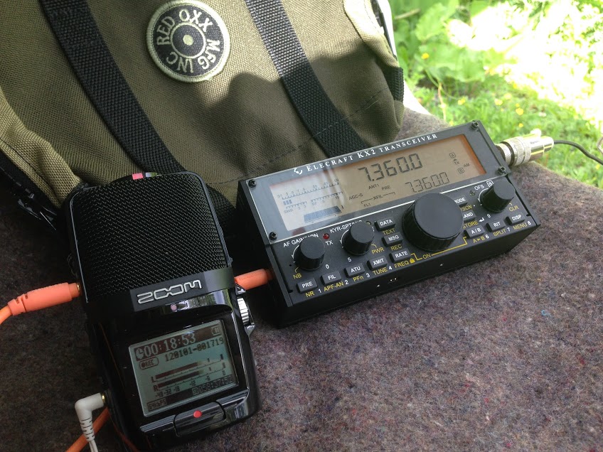
The Zoom H2N connected to my Elecraft KX2.
Another limiting factor is that I only have one stand-alone digital audio recorder: the Zoom H2N. [Although inspired by Matt’s multi-track comparison reviews, I plan to upgrade my gear soon.]
The IC-705 has built-in digital audio recording and this is what I used in each test.
The WinRadio Excalibur and Airspy HF+ also have native audio recording via their PC-based applications.
With only one stand-alone recorder, I wasn’t able to simultaneously compare the IC-705 with more than one other stand-alone receiver/transceiver at a time.
As I mentioned in each test, the audio levels were not consistent and required the listener to adjust their volume control. Since the IC-705, Excalibur, and HF+ all have native recording features, the audio levels were set by their software. I didn’t post-process them.
Blind Audio Survey Results
With all of those caveats and disclaimers out of the way, let’s take a look at the survey results.
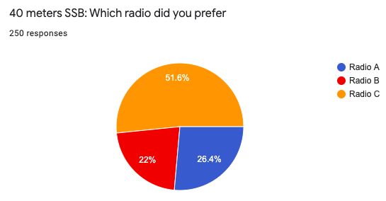
Blind audio test #1: 40 meters SSB
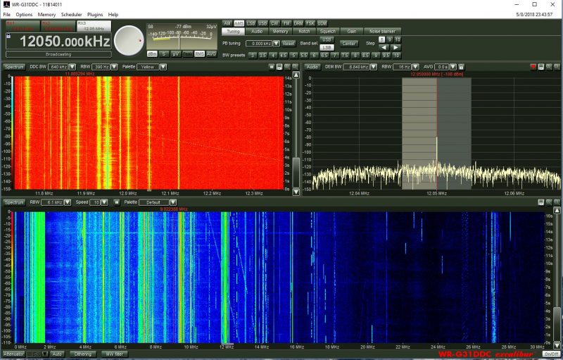
In this first test we listened to the IC-705, WinRadio Excalibur, and Belka-DSP tuned to a weak 40 meter station in lower sideband (LSB) mode. Specifically, this was ham radio operator W3JPH activating Shikellamy State Park in Pennsylvania for the Parks On The Air program. I chose this test because it included a weak station calling CQ and both weak and strong stations replying. There are also adjacent signals which (in some recordings) bleed over into the audio.
Radio A: The Belka-DSP
Radio B: The WinRadio Excalibur
Radio C: The Icom IC-705
Survey Results
The Icom IC-705 was the clear choice here.
Based on your comments, those who chose the IC-705 felt that the weak signal audio was more intelligible and that signals “popped out” a bit more. Many noted, however, that the audio sounded “tinny.”
A number of you felt it was a toss-up between The IC-705 and the Belka-DSP. And those who chose the WinRadio Excalibur were adamant that is was the best choice.
The WinRadio audio was popping in the recording, but it was how the application recorded it natively, so I didn’t attempt to change it.
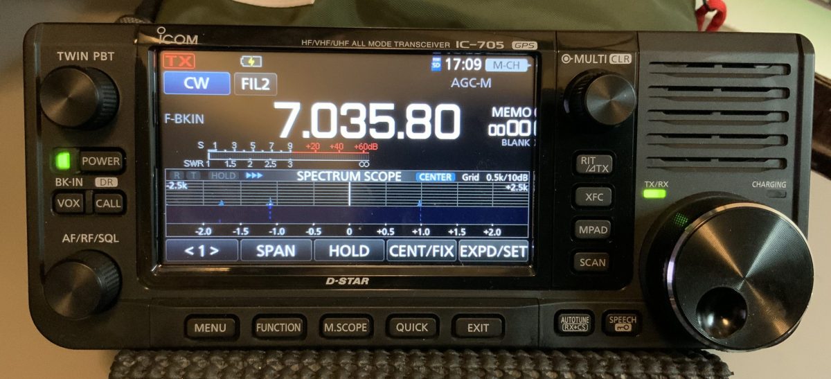
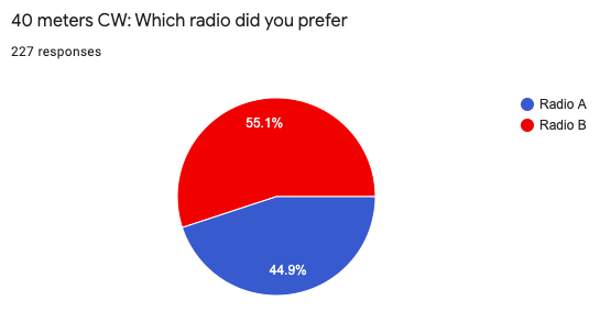
Test #2: 40 meters CW
In this second test we listened to the Icom IC-705 and the Elecraft KX3 tuned to a 40 meter CW station.
Radio A: Icom IC-705
Radio B: Elecraft KX3
Survey Results
The Elecraft KX3 was preferred by more than half of you.
Based on your comments, those who chose the KX3 felt the audio was clearer and signals had more “punch.” They felt the audio was easier on the ears as well, thus ideal for long contests.
Those who chose the IC-705, though, preferred the narrower sounding audio and felt the KX3 was too bass heavy.
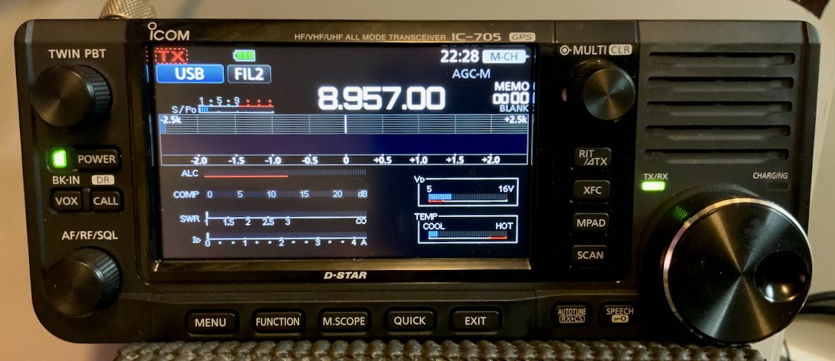
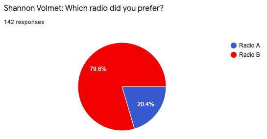
Test #3: Shannon Volmet SSB
In this third test we listened to the Icom IC-705 and WinRadio Excalibur, tuned to Shannon Volmet on 8,957 kHz.
Radio A: WinRadio Excalibur
Radio B: Icom IC-705
Survey
The Icom-705 audio was preferred by a healthy margin. I believe, again, this was influenced by the audio pops heard in the WinRadio recording (based on your comments).
The IC-705 audio was very pleasant and smooth according to respondents and they felt the signal-to-noise ratio was better.
However, a number of comments noted that the female voice in the recording was actually stronger on the WinRadio Excalibur and more intelligible during moments of fading.
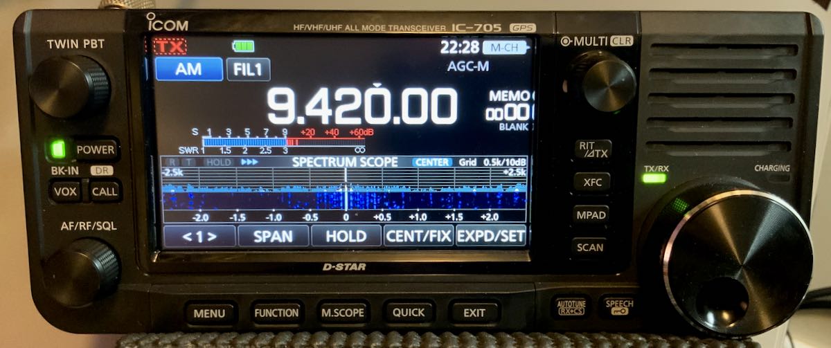
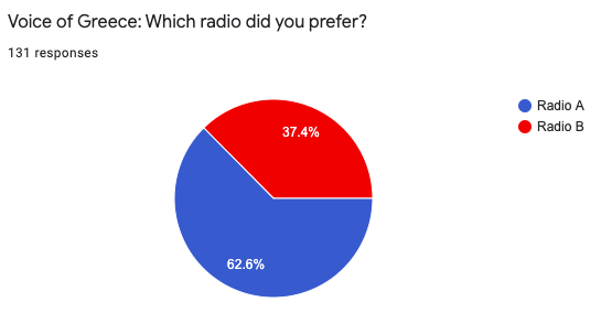
Test #4: Voice of Greece 9,420 kHz
In this fourth test we listen to the Icom IC-705, and the WinRadio Excalibur again, tuned to the Voice of Greece on 9,420 kHz.
Radio A: Icom IC-705
Radio B: WinRadio Excalibur
Survey
While the preference was for the IC-705’s audio (Radio A), this test was very interesting because those who chose the Excalibur had quite a strong preference for it, saying that it would be the best for DXing and had a more stable AGC response. In the end, 62.6% of 131 people felt the IC-705’s audio had slightly less background noise.
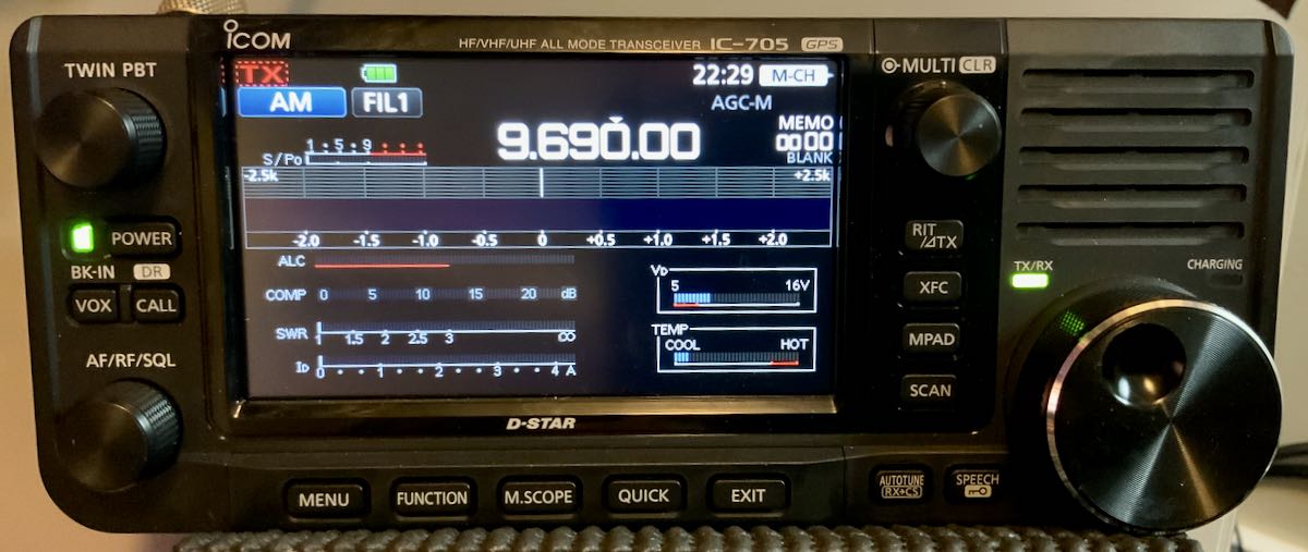
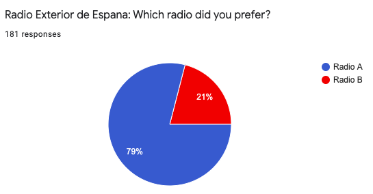
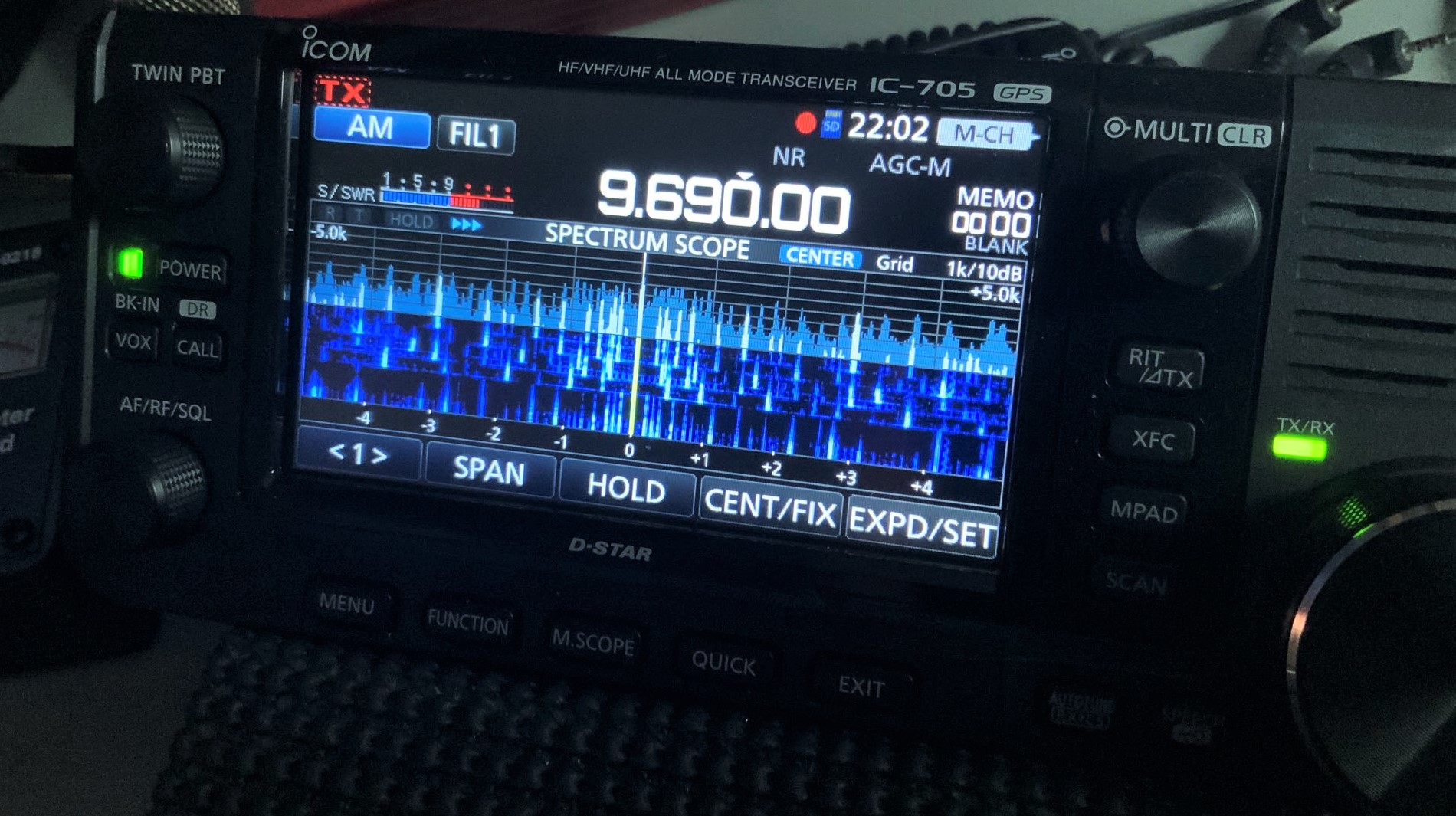
Test #5: Radio Exterior de España 9,690 kHz
In this fifth test we listened to the Icom IC-705, and AirSpy HF+, tuned to Radio Exterior de España on 9,690 kHz. I picked REE, in this case, because it is a blowtorch station and I could take advantage of the IC-705’s maximum AM filter width of 10 kHz.
Radio A: Icom IC-705
Radio B: Airspy HF+
Survey
The IC-705 was preferred by 79% of you in this test.
Again, very interesting comments, though. Those who preferred the IC-705 felt the audio simply sounded better and had “punch.” Those who preferred B felt it was more sensitive and could hear more nuances in the broadcaster voices.
So what’s the point of these blind audio tests?
Notice I never called any radio a “winner.”
The test here is flawed in that audio levels and EQ aren’t the same, the settings aren’t identical, and even the filters have slightly different shapes and characteristics.
In other words, these aren’t lab conditions.
I felt the most accurate comparison, in terms of performance, was the 40M CW test with the KX3 because both employed similar narrow filters and both, being QRP transceivers, are truly designed to perform well here.
I essentially crippled the WinRadio Excalibur and Airspy HF+ by turning off all all but the most basic filter and AGC settings. If I tweaked both of those SDRs for optimal performance and signal intelligibility, I’m positive they would have been the preferred choices (indeed, I might just do another blind audio test to prove my point here).
With that said, I think we can agree that the IC-705 has brilliant audio characteristics.
I’ve noticed this in the field as well. I’m incredibly pleased with the IC-705’s performance and versatility. I’ll be very interested to see how it soon rates among the other transceivers in Rob Sherwood’s test data.
The IC-705 can actually be tailored much further by adjusting filter shapes/skirts, employing twin passband tuning and even using its noise reduction feature.
If anything, my hope is that these blind audio tests give those who are considering the Icom IC-705 a good idea of how its audio and receiver performs in real-word listening conditions.
I recently posted results from my listening endurance test with the new Icom IC-705 QRP general coverage transceiver. I’ve been on a mission to see just how long the supplied BP-272 Li-ion battery pack can hold up with a full charge in real-world conditions.
Thursday, I took the IC-705 to the field and activated a park using only the charged battery pack. After nearly 2 hours of constant operation (calling CQ and working stations) the BP-272 still had nearly 40% of its capacity.
That’s better than I expected, especially knowing the BP-272 is the slim, lower capacity battery pack.
I have to admit: that was a particularly fun activation because propagation finally gave me a break and I worked stations from the Azores to Oregon on a mere five watts of power.

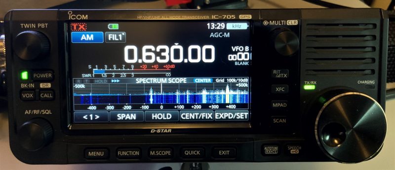 From my home, WAIZ is a tough catch, so it was weak, but I could hear it.
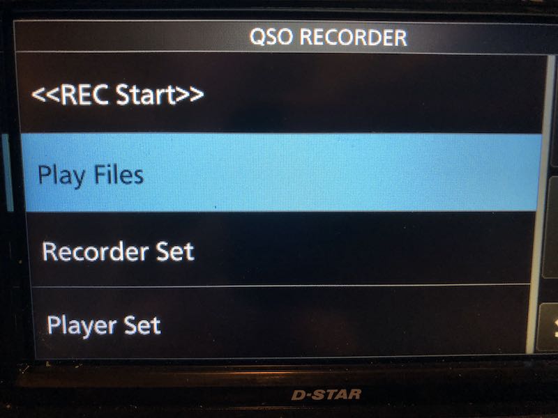
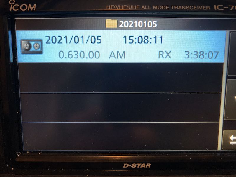 Here’s the genius bit for those of us who like to archive broadcast recordings…the IC-705 embeds the following meta data:
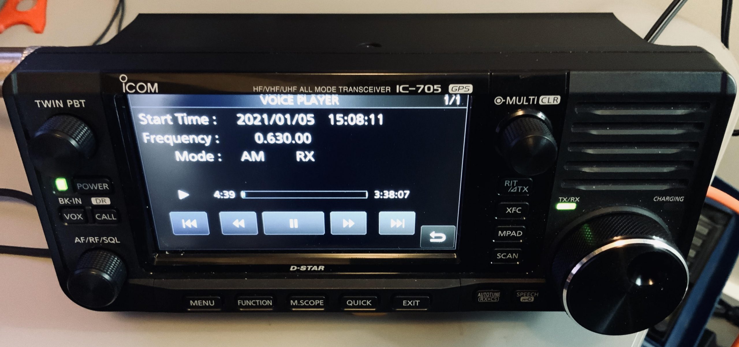 The built-in player displays the meta data, and even includes a number of controls like fast-forward, rewind, skip to next or previous file. and pause.