Shortwave listening and everything radio including reviews, broadcasting, ham radio, field operation, DXing, maker kits, travel, emergency gear, events, and more
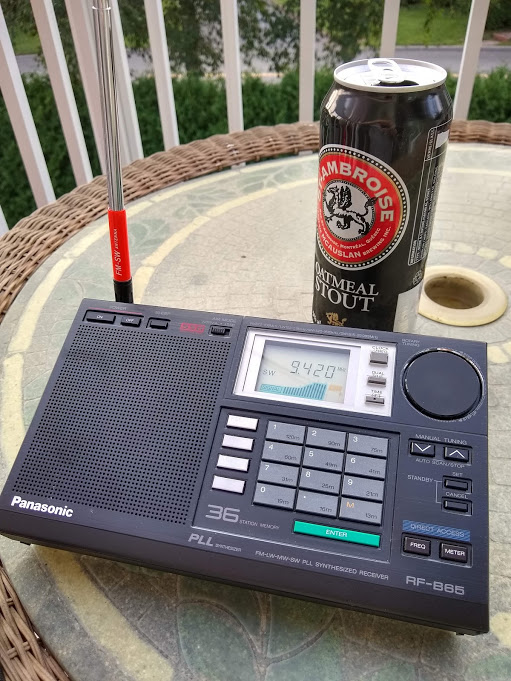
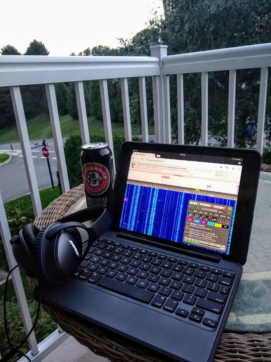
While I love the Panasonic RF-B65, the Voice of Greece and a St. Ambroise Oatmeal Stout: this combo can’t fight the persistent radio interference here at the condo.
Some of you might recall that I’m spending the months of August and September in a condo near Québec City, Canada. We love it here, though it does present some radio challenges. Unlike our rural/remote mountain home in the States, I’ve always had to cope with QRM (manmade radio interference) here at the condo. Not surprising.
I typically bring my PK Loop antenna–it helps lower the noise a tad and is easy to take out on our balcony for optimal reception. Lately, though, the QRM has been even worse on the balcony than inside the condo (more on that in a future post).
Some North American and European stations punch through the noise when propagation is favorable (especially the Voice of Greece and Radio Romania International) but there have been evenings where nothing could penetrate the wall of noise.
One way I escape the noise, of course, is to take my radio to a picturesque remote location for the afternoon or evening. It’s amazing the number of signals you can pull out of the ether when the noise floor is so low.
Back at the condo, though, there’s no easy way to escape the noise.
Or is there?
Impromptu DXpeditions
Perhaps 21st century problems require 21st century solutions.
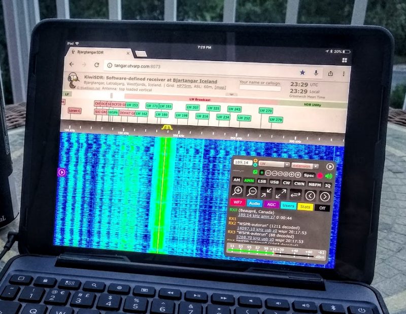
This year–especially here at the condo–I’ve spent a great deal of time exploring the KiwiSDR network.
For those of you not familiar, the KiwiSDR is a self-hosted WebSDR which operates much like a mini U Twente WebSDR. KiwiSDR owners install their SDRs at home–or in other favorable locations–then share control of their SDR with the world via the the Internet.
Like the U Twente WebSDR, KiwiSDRs allow multiple simultaneous users to control the SDR independently of each other. Each KiwiSDR can allow up to four simultaneous guests (the U Twente WebSDR can allow hundreds of simultaneous users, but it’s also a university-supported bespoke SDR with fantastic bandwidth!).
Over the past few years, the KiwiSDR network has grown almost exponentially. There are Kiwi SDRs on every continent save Antarctica (someone remedy that, please!).
Each red pin represents a KiwiSDR installation.
Other than the fact that the SDR audio is piped through the Internet–and you can’t walk outside and adjust the antenna–there is no difference between using a KiwiSDR remotely or locally.
In fact, the KiwiSDR only has a web browser-based application, there is no downloadable application for local use. So quite literally, the experience of controlling and using a KiwiSDR locally or globally is identical.
And it’s so much fun! I browse the KiwiSDR network via the map above, select an interesting location, and virtually travel there for an impromptu DXpedition. I can travel to India, Italy, Japan, New Zealand, or Hawaii via the network and be back in time for dinner here in Canada without breaking a sweat or even using frequent flyer miles!
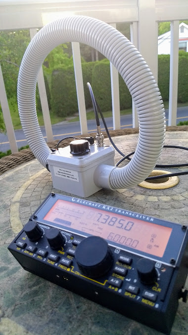
I’ve found that the combo above makes for an immersive experience. I use Bose Quiet Comfort noise-cancelling headphones paired with my iPad Air (which I have enclosed in a Zagg Rugged Book). With a reasonable Internet connection, it truly feels like I’m there.
Of course, you don’t need an iPad, or any special equipment. The KiwiSDR application works with pretty much any computer, tablet or smart phone that has a web browser. For the best experience, however, I would suggest connecting a good external speaker, bluetooth speaker or headphones.
I know many of you are thinking, “But Thomas! This isn’t real radio!”
But I would argue that it is real radio! It’s a real radio, connected to a real antenna that you’re simply controlling via the Internet with a web-based SDR application. Instead of the audio going through a sound card into your headphones, it’s going into a soundcard, piped through the Internet, then into your headphones.
Give it a try! You might find an impromptu DXpedition is the perfect remedy to your QRM and RFI blues!
Post readers: Any heavy KiwiSDR users out there? Or do you oppose using WebSDRs? What are your thoughts? Please comment!
Many thanks to SWLing Post contributor, Justin Patrick Moore (KE8COY), who is a radio host, radio enthusiast and musician. At my request, Justin has shared the following article excerpts from his blog that discuss the convergence of music and radio:
Imaginary Landscapes
The development of telecommunications technology and electronic circuits had a major impact on the creation of new musical instruments from the very beginning, but it was only in 1951 that a composer first got the idea that the radio itself could be used as a musical instrument. Since then the use of radio as a source for live, unpredictable sound, music, and voice has become commonplace across the genres of contemporary classical music, and various styles of electronic, rock and pop music. Using the radio as an instrument has become part of what composer Alvin Curran has called a “new common practice” and is just one of many methods being used to create the sonic backdrop of the landscape we now inhabit in this age of electronic multimedia.
“It’s not a physical landscape. It’s a term reserved for the new technologies. It’s a landscape in the future. It’s as though you used technology to take you off the ground and go like Alice through the looking glass.” John Cage wrote this about his series of Imaginary Landscape compositions. Imaginary Landscape No. 4 was first performed in 1951 and is scored for 12 radios played by 24 musicians, two on each radio, one to control the tuning, the other to control the volume. It is a great example of indeterminate music. The only guarantee about the piece is that no performance of it will never be heard the same way. This is guaranteed because John incorporates chance operations to determine how much the dials of each radio are to be turned by each performer. The novelty of each performance is also guaranteed by the nature of radio itself. Depending on the place and time of a performance, the things coming out of the radio speakers are going to be different. During its premier concert at Columbia University’s McMillin Theater those in the audience heard the word “Korea” over and over again, as well as snippets of a Mozart violin concerto, news about baseball, static, and silence. The performance took place around midnight and many of the stations in New York had already gone off the air for the night. Of course the silence never bothered Cage, who considered in an integral part of the experience. He had said that “silence, to my mind is as much a part of music as sound.”
Radio is the perfect medium for the diffusion of electronic music. The unpredictable sounds coming from radios are also a perfect source material. In many cases the production studios available at broadcast facilities made them the first laboratories for the scientific investigation of sound, for the sole purpose of making music, to be used by electronic music pioneers. Likewise these stations became the first to introduce electronic and other avant-garde music to the public. Such was the case with Westdeutscher Rundfunk, or WDR, the German public broadcasting institution located in Cologne. Their Studio for Electronic Music was the first of its kind in the world and became an epicenter for musicians working in the new medium. On the broadcasting side the WDR promoted new music through unique programming that included radio lectures, the playing of live and recorded music, and commissioning new works from composers working in the field.
As the world caught wind of the work being done at the WDR’s Electronic Music Studio, other radio stations and broadcasting corporations followed suit. NHK (Nippon HosoKyokai) in Japan built their electronic music studio in 1955, directly modeling it on the one at WDR. In 1958 the BBC created their famous Radiophonic Workshop. (I blame starting to watch Doctor Who as a ten year old, with its strange soundtrack and incidental music, for what became my lifelong fascination with electronic music.) The studio at NHK was just over ten years old when they invited Karlheinz Stockhausen over to work there and create two pieces for their airwaves.
When he arrived in Japan Karlheinz was severely jet lagged and disoriented. For several days he couldn’t sleep. That’s when the strange hallucinatory visions set in. Laying awake in bed one night his mind was flooded with ideas of “technical processes, formal relationships, pictures of the notation, of human relationships, etc.—all at once and in a network too tangled up to be unraveled into one process.” These musings of the night took on a life of their own and from them he created Telemusik.
Starting in the early 1960s Karlheinz Stockhausen composed several instrumental works which he called “process compositions”. These did away with traditional stave notation and instead used symbols including plus, minus, and equal signs that indicated the successive transformations of sounds that were otherwise unspecified or unforeseeable by the composer. In this way he brings elements of improvisation into the fold of Western classical music where the strict adherence to a fixed score left little room for interpretation by musicians. The scores in his process pieces don’t dictate specific notes or ways of playing but rather specify the way a sound is to be changed or imitated. Taking a cue from his studies of information theory Stockhausen created a way of writing music that is similar to computer programming. The program “determines the way information is processed while leaving the choice of information to be processed to the individual user.” (Maconie 1990, 156-157)
Stockhausen’s process pieces include Plus-Minus (1963), Prozession (1967), Kurzwellen, and Spiral (both 1968). Eventually they led to the text based processes of his intuitive music compositions in the cycles Aus den sieben Tagen (1968) and Für kommende Zeiten (1968–70).
Kurzwellen (Short waves), the third of the process pieces also marks the beginning of Stockhausen’s magnificent voyage using shortwave receivers as a medium for musical transportation. The formal procedures in Kurzwellen (and the others) are fixed. Stockhausen thinks of these not as fixed in the way Beethoven’s Fifth symphony is a fixed piece that will sound the same to a greater or larger degree from recording to recording or performance to performance. Only the processes themselves are fixed. These are indicated primarily by plus, minus, and equal signs and constitute the composition.
Yet the sound materials themselves, like the knobs on the tuners, are variable. The process scores can be followed and bring about very different results each time they are played and yet somehow still sound similar. The sound material coming in from the shortwave radios is unpredictable. Yet the prescribed processes themselves can be heard from one performance to another as being “the same”. These developments in musical theory and practice make live performances and new recordings exciting events.
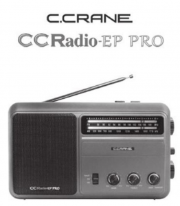
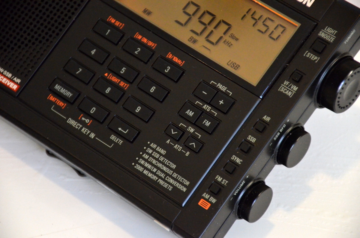
Remember the American television game show To Tell The Truth? This very long-running show challenged four celebrity guests and viewers to identify the real “central character” in the midst of two impostors.I was reminded of this game show when attempting to tell the difference between the original and recently updated versions of C. Crane’s CCRadio-EP Pro receiver when viewing the front panels. If there’s a difference, I can’t spot it! You need to turn around the radios to see the new EP-Pro’s key feature: switchable 9 kHz/10 kHz tuning steps.
The only clue to the newest version of the CCRadio-EP Pro is the 9/10 kHz tuning switch on the back panel.
I recently met with a good friend and radio hobbyist from Oregon to compare a few selected portable radios, FSL (Ferrite Sleeve Loop) antennas, and the newest low-noise Wellbrook ALA100LN module that was introduced just a few weeks ago. I was particularly interested in a head-to-head match-up of my friend’s original EP-Pro versus my newly arrived EP-Pro (9 kHz/10 kHz steps) version.
I’m looking forward to Thomas’ usual thorough review of the new CCRadio-EP Pro, but I want to offer a few observations of medium wave tuning after my time with the two models:
On very weak daytime MW signals, the radios are equally sensitive except on higher frequencies where the new model excels to a moderate degree. It’s enough of an advantage to make the difference between catching an ID or not on a low, DX-level signal.
The new EP-Pro feels more accurate–and simply more enjoyable–to tune, thanks to the elimination of false “peaks” surrounding the main signal. This is a BIG plus for the new radio, and frankly the CCRadio-EP should have performed this way from the start. Kudos to C. Crane for correcting this problem, but I can understand why the original version was brought to market with the odd tuning quirk. It isn’t a deal breaker for most non-DXing purchasers.
I could not find an instance of soft muting on either radio. I listened for a while to signals barely above the noise floor, and never did audio “cut in and out” suddenly, a clue to soft muting. Both receivers are very useful for chasing weak MW stations…but the new version is highly preferred for ease of tuning because of the lack of false audio peaks.
With the tuning working way it should, medium wave channels “snap” in and out as you slowly tune. This took a little getting used to, but after a while I began to appreciate the sense of exactness with the newest CCRadio-EP Pro.
Fast excursions up or down the band (either radio) will blank the audio, recovering when you stop tuning or slow down. I believe this is simply a case of exceeding the AGC’s recovery time, not soft muting. It’s easy to live with, but granted the effect is not one of smoothness as found on traditional, non-DSP analog receivers. Successful DXing takes a slower approach anyway when scanning the band; casual listeners may be more annoyed by either version of the radio if they are used to very quick knob-cranking.
The Twin Coil Ferrite “AM Fine Tuning” control works well on both units, and gives significant gain to weak signals on either extremity of the band. I love this feature; it makes digging out the weak ones a lot more fun!
So, should you buy the newest CCRadio-EP Pro with the 9 kHz/10 kHz steps?
If you already own a CCRadio-EP Pro and are fine with the false tuning peaks and have no desire for the 9 kHz MW step option–keep your radio! Only on high band does the new model have a sensitivity edge. Especially don’t make the jump if you’re a casual listener and listen only to a handful of local stations, or a single distant station.
If you do not own a CCRadio-EP Pro yet, but are in the market, definitely buy the newest version. Be aware that you can only be assured of getting the newest model if you purchase directly from C. Crane. Amazon does not yet carry the newest version according to some reports.
If you’re a radio junkie and just have to have both…go ahead…we understand!
I also made a short video comparison of the new EP Pro versus the top-ranked Panasonic RF-2200 on medium wave:
Guy Atkins is a Sr. Graphic Designer for T-Mobile and lives near Seattle, Washington. He’s a regular contributor to the SWLing Post.
Many thanks to SWLing Post contributor, Gary DeBock, for sharing the following guest post:
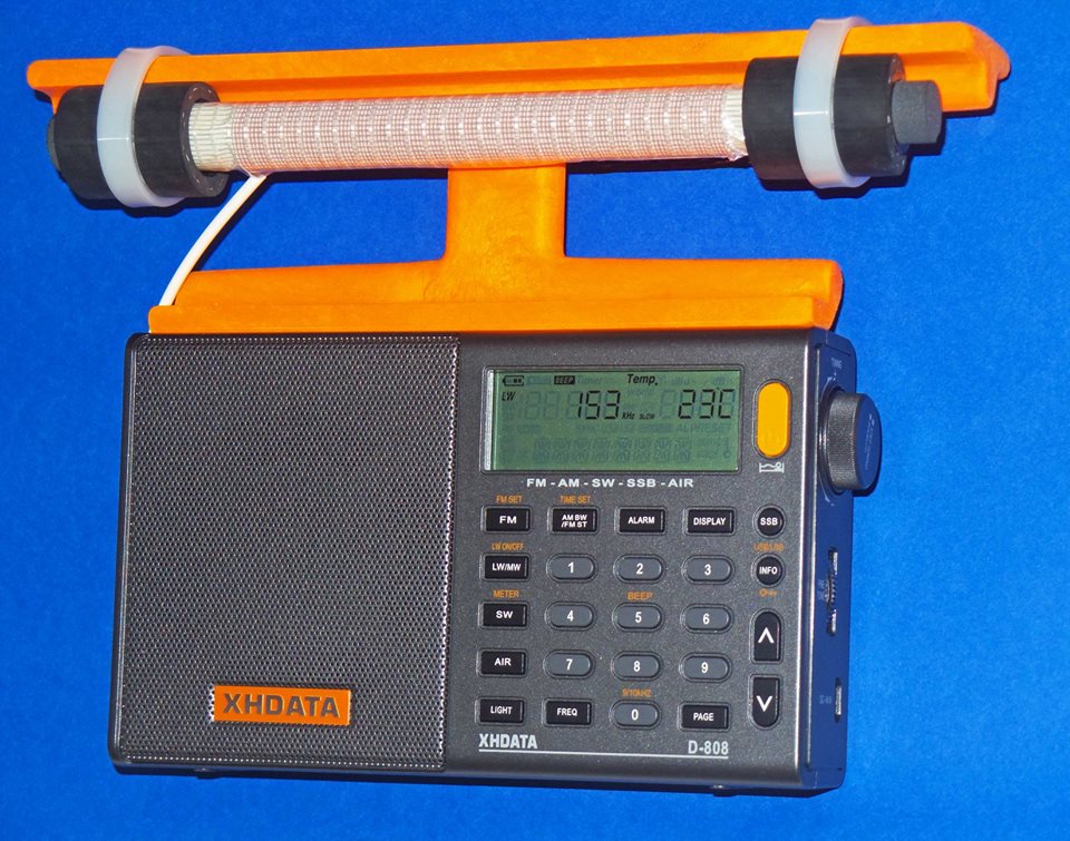
Supercharging the XHDATA D-808
Installation of High Performance AM and LW Loopsticks
By Gary DeBock, Puyallup, WA, USA, September 2018
Introduction
As a stock receiver the Chinese-made D-808 AM-LW-FM-SW-AIR portable is a very capable performer, with AM reception superior to that of any current Ultralight model, and impressive FM reception as well. The radio was certainly “inspired” (to use a generous term) by the C.Crane Skywave SSB model, which coincidentally was manufactured in the same part of China by C.Crane’s Redsun partner—with the first units going out the door a few months before the D-808 came into existence.
Because foreign intellectual property is routinely copied in China with no punishment from the government, XHDATA essentially had the chance to copy all the good points in the Skywave SSB design and improve upon its weak points as well. The only precaution that XHDATA took after this wholesale design appropriation was to forbid direct shipments of the D-808 from China to North America—presumably to avoid a copyright lawsuit by C.Crane. As such, the first D-808 models were sold to the rest of the world around January of 2018 at a price about half that of the Skywave SSB, while North American DXers were told that since the model couldn’t be shipped to the USA or Canada, they were out of luck.
Of course some D-808 models did make it into North America, where it was found to be a very capable portable with astonishing value for the price. Finally around March, an enterprising Chinese eBay seller came up with a plan to ship the model to North America through Israel, thereby skirting around XHDATA’s direct shipment prohibition. As of late August this eBay seller (harelan ecommerce) has already sold 62 of the D-808 models this way, even though he charges a premium for shipment to North America. Whether this single supply source will continue to serve North American customers is currently unknown, but out of the 7 models that I have purchased from him there hasn’t been a single D-808 model with any issues– despite the apparent lack of any manufacturer’s warranty offered on the radio.
Despite the D-808’s rather dubious design pedigree there is no doubt that the Chinese engineers (or reverse engineers?) did a superb job in creating an awesome radio for the money. Besides directly copying the Skywave’s SSB design and controls, XHDATA also made significant improvements, including a longer loopstick (providing clearly superior AM sensitivity), a much more powerful audio amplifier (correcting a serious shortcoming in the Skywave SSB) and a much lower price (about half that of the $169.99 Skywave SSB, for models shipped outside North America). Another great advantage for someone wishing to perform this loopstick upgrade are the perfectly located, highly accessible Litz wire connections on the RF circuit board—apparently used by the Chinese engineers to conveniently test out various loopsticks, and retained in the final product. The radio’s high quality construction and survivability in adverse conditions were proven repeatedly over the summer here, with the model surviving accidental exposure to a 104 degree (43 degrees C) car trunk temperature, exposure to moderate rain, repeated travel bumps, and use as the main receiver during a 9-day DXpedition to a plunging ocean side cliff in Oregon state. The 3.7v lithium-ion rechargeable battery provides superior run time for extended DXing sessions, and is included in the D-808 shipping package, along with a USB cord to charge the battery, a plug-in wire antenna (for FM,SW and AIR), a vinyl carrying case, and a pretty basic English instruction manual.
One thing you will NOT find supplied with the D-808 is a warranty card– either in the shipping box, or online. This is pretty standard practice in China, incidentally, where concepts like refunds and warranties aren’t generally part of customers’ expectations. This doesn’t necessarily mean that XHDATA won’t repair obvious problems in a new D-808, but it does mean that they aren’t assuming the obligation to do so. I have heard from one North American purchaser who received a new D-808 with a defective speaker, and he is still waiting for the model to be repaired (after paying the shipping charge to send it back to China). Each individual purchaser must decide whether or not this lack of any warranty is a deal breaker. But if you are looking for a final reason to perform this loopstick transplant, why not consider the fact that you will not be violating any manufacturer’s warranty by doing so??
Realistic Expectations
Although this 7.5” loopstick upgrade will certainly make your D-808 far more sensitive than the stock model on Medium Wave or Longwave, it is not designed to compete with large (2’ sided or larger) inductively coupled box loops, or any of the new FSL antennas. The sensitivity upgrade will boost the D-808’s MW band weak-signal performance up to the level of classic portables like the ICF-2010 and RF-2200; however, and since the D-808’s DSP-enhanced selectivity will generally exceed that offered by these classic portables, the overall DXing capability in the AM mode could be considered slightly greater. The D-808 does have SSB capability, although it lacks the SSB tuning convenience offered by the ICF-2010 and RF-2200. It also lacks the ICF-2010’s superb Synch detector, a big advantage in weak signal DXing. But in portability, versatility and DXing value for the price, the “Supercharged” D-808 is a real winner.
Project Overview
This construction article will provide the builder with step-by-step instructions to upgrade the XHDATA D-808’s loopstick to a much more sensitive, externally-mounted 7.5” Medium Wave or Longwave loopstick replacement. Both the Medium Wave and Longwave 7.5” loopstick designs have been thoroughly tested and proven effective in actual DXing by hobbyists other than the author, and as long as the instructions are followed carefully, this relatively inexpensive modification will provide a major improvement in the D-808’s weak-signal reception capability.
This modification project involves close-order soldering on the D-808’s circuit board, and should only be attempted by builders with reasonably good eyesight, good hand coordination and soldering experience. The project also calls for the use of a precut plastic loopstick frame to attach the antenna to the top of the D-808’s top back cabinet surface, and the construction of this precut plastic frame requires either the use of a 12” (or larger) power miter saw, or some rather lengthy cutting with a hacksaw. Use of a power miter saw SHOULD NOT be attempted by those without serious power tool experience! The author assumes that only qualified power tool operators will attempt to use a 12” miter saw to cut these frames quickly, and that other builders who wish to construct them will use a hacksaw. As such, only basic cutting instructions are provided for the 12” power miter saw users, while detailed instructions are provided for the hacksaw users. To assist builders who are not qualified to use power tools, the author has prepared a LIMITED number of these precut plastic loopstick frames on a power miter saw, which will be offered at cost to these builders on a first come, first served basis.
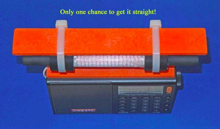
A final warning is in order concerning the step of gluing the precut plastic loopstick frame to the D-808’s top back cabinet surface. Although this step is not dangerous, it is pretty tricky. Since the superglue “grips” very rapidly, you will only get one chance to ensure that the frame is straight, and centered on the D-808’s top cabinet surface. Do yourself a favor, and make multiple “dry runs” to practice this important step before applying the glue! Failure to take this step seriously will probably result in a crooked loopstick frame—which will hold the antenna just fine for DXing purposes, but which will be an eternal reminder to the DXer (and everyone else) of the hazards of haste.
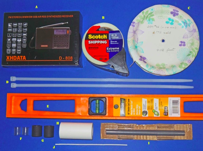
Construction Parts Required
This 7.5” loopstick D-808 construction article will guide you through the assembly of either a 7.5” Medium Wave loopstick D-808 or a 7.5” Longwave loopstick D-808, so make sure that you order the parts necessary for construction of your chosen model. The picture above shows the parts that will be necessary for construction of either model, but the Litz wire and 7.5” ferrite rod components differ according to whether you are building the Medium Wave or Longwave model.
A) XHDATA D-808 Receiver, currently available to North American purchasers (for $112.87 + $10. Click here to search eBay.
B) Scotch brand “Extreme” strapping tape (any size roll)
Miscellaneous: One packet of Duro Super Glue (.07 ounce size), solder, 25w (low heat) soldering iron, hacksaw (or power miter saw), screwdriver set, sandpaper, needle nose pliers, diagonal cutters
D-808 Radio Preparation
Before starting the modification give the radio a thorough test on all bands, ensuring that all the stock model functions work properly, and that there are no issues with the display, speaker, headphone jack, battery or charging system. It’s also a good idea to run a daytime DX band scan on the AM or Longwave band (for whichever band you plan to construct an upgrade loopstick) and document the results—to use as a benchmark for the upgrade loopstick’s performance.
Step-By-Step Construction
Antenna Frame and 7.5 inch Loopstick Preparation
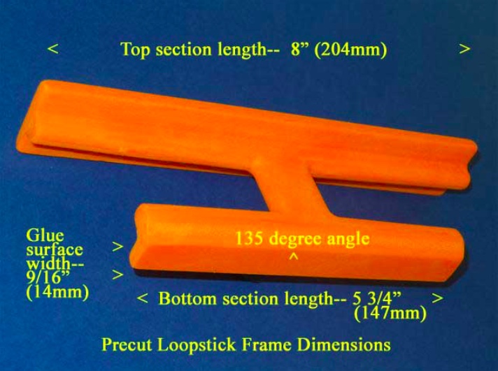
1) Refer to the photo below. Using the “Supercharging the Tecsun PL-380” article (posted at http://www.mediafire.com/file/du3sr5cd9thqvau/7.5inch-LS-PL380.doc/file or available directly from the author) carefully prepare the orange loopstick antenna frame according to construction steps 1-9, EXCEPT note that the lower (glue surface) edge of the antenna frame should be cut to a length of 5 3/4” (147mm), NOT 5” (127mm) as described in the PL-380 transplant article. Pay close attention to the safety precautions concerning power tool usage, and DO NOT attempt to use a power miter saw unless you have SERIOUS power tool experience!
2) If you are constructing an AM (Medium Wave) loopstick, follow construction steps 10-16 in the PL-380 transplant article to construct the antenna. If you are constructing a Longwave loopstick, follow construction steps 10a-16a in the PL-380 transplant article to construct the antenna. If you are constructing both loopsticks, MAKE SURE that the ferrite rod and Litz wire are only used in the antennas for which they were designed. Mixing up these items is very easy, and such a mistake will make both loopsticks perform like clunkers.
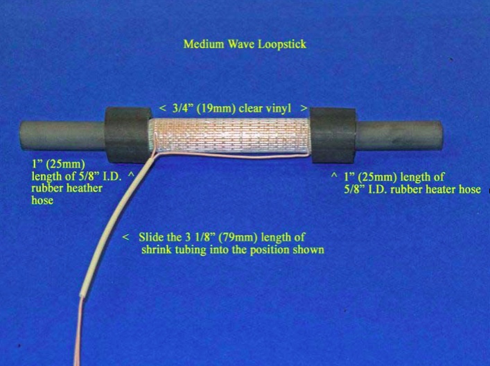
3) After construction of either the AM or Longwave loopstick, follow the instructions in steps 29 and 30 of the PL-380 transplant article to install a piece of 3 1/8” (79mm) shrink tubing, EXCEPT note that this length is slightly longer than the 3” (76mm) length called for in the PL-380 article.
4) Refer to the photo below for the following three steps. [NOTE: Although this photo shows the AM (Medium Wave) loopstick, the procedures in this step are the same for the Longwave loopstick, although the position of the rubber hose lengths and clear vinyl inserts will be closer to the ends of the ferrite rod]. Carefully slide the length of 3 1/8” shrink tubing into the position shown, ensuring that there are no Litz wire kinks or bends inside the shrink tubing.
5) Take the two 3/4” (19mm) clear vinyl inserts and slide them onto the ferrite rod ends, twisting them up against the border of the Scotch “Extreme” tape ends to lock the tape in place under the vinyl inserts. Ensure that the clear vinyl inserts do not touch any Litz wire leads or coil turns.
6) Slide the 1” (25mm) lengths of rubber heater hose over the clear vinyl inserts until the appearance of the loopstick resembles the above photo. Ensure that the rubber hose sections also do not touch either the Litz wire leads or any coil turns. Finally, place the completed loopstick in a safe place until it is called for in Step .
Radio Disassembly
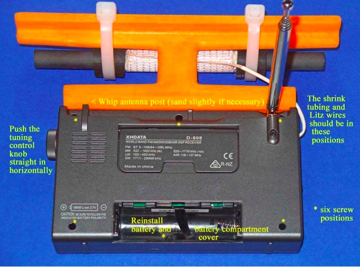
7) Refer to the photo above for this step. Remove the battery from the radio, and using a Jeweler’s Phillips screwdriver of the correct size, remove the six identical screws in the positions shown (NOTE: These screws have a tendency to stick inside their slots, even when the slots are turned upside down. If you cannot remove all six screws it’s not a major problem, but at least ensure that the screws are completely loose in their slots, and that you don’t lose any of them during the remaining steps). Grasp the tuning knob, and pull it out horizontally in a completely straight manner to remove it from the radio. Ensure that the battery, tuning knob and all removed screws are placed in a safe place until the radio is reassembled.
8) Carefully separate the front and back cabinet sections and place them down in the position shown in the photo below. Note that the front and back sections of the radio are connected by a ribbon wire plug-in system– ensure that this plug remains securely inside its slot at all times, and that no great stress is placed on the speaker wires.
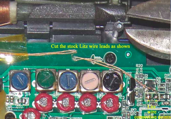
9) Refer to the close up photo below, and note the position of the two Litz wire soldering points on the circuit board (in the lower right corner of the photo). Using diagonal cutters, cut the two Litz wire leads at the position shown, UNLESS you wish to salvage this stock loopstick for other projects—in which case you should desolder the entire lengths of the Litz wire leads from the circuit board at the positions shown in the lower right corner (NOTE: The stock loopstick is of a fairly good design, and has an inductance that would be compatible with any DSP-chip Ultralight radio, providing an AM sensitivity boost in the process).
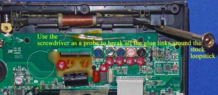
10) Refer to the photo below. Using a flat Jeweler’s screwdriver with a 1/16” blade, carefully probe around all four sides of the stock loopstick to break all of the glue bonds. Work slowly and carefully around the perimeter of the ferrite rod, including the plastic covers on each end. Once most of the glue bonds have been broken the ferrite rod will begin to shift around as you break up the few remaining bonds, but until this point work slowly and patiently to break up the glue.
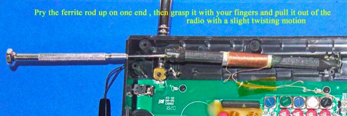
11) Refer to the photo below. Using the flat Jeweler’s screwdriver, once all of the glue bonds have been broken and the ferrite rod is loose in its slot, lift the ferrite rod out of its slot on one side by prying up under the plastic cover on the end of the ferrite rod. Ensure that the Litz wire leads have either been cut or desoldered from the circuit board, then grasp the ferrite rod with your fingers and pull it completely out of the slot with a slight twisting motion.
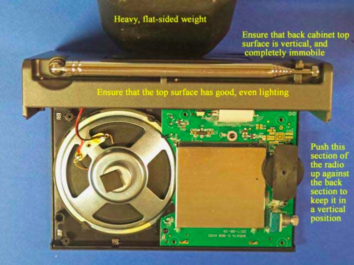
12) Remove the wrist strap, and refer to the photo below. Carefully pick up the two sides of the radio and place the back section in a vertical position as shown, with a heavy flat weight (barbell, or other heavy flat item) pressing up against the back cabinet section to keep it in a vertical position. Ensure that there is adequate, even lighting on the top cabinet section for the gluing process in the next step, and that the back cabinet surface will not shift around as you make the gluing “dry runs,” and perform the actual gluing of the loopstick frame to the top of the cabinet.
13) Take the previously prepared orange plastic loopstick frame, and ensure that its bottom glue surface is completely smooth and flat, with no uneven ridges on the edges of the glue surface (remove these with fine sandpaper, but ONLY on the ridges, and not on the rest of the flat glue surface). Using a damp paper towel, wipe the top cabinet glue surface and the loopstick frame glue surface to remove any dust or debris, then wipe them again with a dry, clean paper towel to ensure that they are both completely dry.
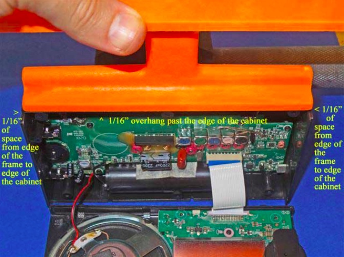
Take the loopstick frame and gently slide the frame over the top cabinet surface to ensure that both surfaces are smooth and flat. Refer to the photo at the top of the next page. Ensure that there is even, bright lighting on the top cabinet surface, and make several “dry runs” to place the loopstick frame in the exact center of the top cabinet surface (with 1/16”, or 1.5mm of space between the frame ends to the cabinet ends), and also 1/16” (1.5mm) of overhang above the front edge of the cabinet’s glue surface (NOTE: if you wish to simplify the process by lining up the front edge of the loopstick frame with the front edge of the cabinet’s glue surface it will still provide an acceptable result, but you will need to do some minor sanding of the whip antenna’s plastic slot post, as shown in the photo below. In either case, make repeated “dry runs” with the loopstick frame to practice placing it in the exact center of the top cabinet’s glue surface, since you will only get one chance to place it in the proper center position once the superglue is applied.
NOTE: The back of the loopstick frame has a beveled surface to permit full operation of the radio’s whip antenna after the frame is glued on the top of the cabinet surface. If the loopstick frame is glued with a 1/16” (1.5mm) overhang in front of the front edge of the cabinet surface then the whip antenna should have enough space for free operation. The alternative is to glue the two front edges lined up with each other to simplify the gluing process, in which case minor sanding may be required on the whip antenna slot post, as shown in the photo below.
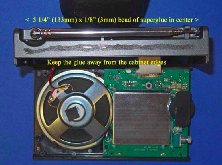
14) After making multiple “dry runs” and becoming familiar with accurate placement of the loopstick frame on top of the cabinet, refer to the photo at the top of the next page. After once again ensuring that the back cabinet section will not shift around during the gluing process, take the Duro superglue packet and apply a thin (1/8”, or 3mm) bead of glue along the center of the cabinet’s glue surface, extending it 5 1/4” (133mm)long, with equal spaces on both ends (as shown). While sighting the two sides place the loopstick frame carefully down in the correct center position as practiced previously, with the 1/16” overhang if desired. If satisfied with the position, press down on the frame to lock the two surfaces together securely. Usually the frame may be shifted around slightly within 1 or 2 seconds of placing it on the superglue, so use this brief time to promptly shift the frame to a straight position, if necessary. After a couple of seconds, though, you will need to be satisfied with whatever position the frame has ended up with (regardless, it will still hold the loopstick just fine, for DXing purposes).
15) After the loopstick frame is securely placed and locked on top of the D-808’s cabinet surface, place downward pressure on the loopstick frame along its length in order to ensure a tight glue bond throughout the entire top cabinet surface. Continue this process for about one minute, and sight both ends of the loopstick frame to ensure that they are both completely flat against the D-808 cabinet.
16) Inspect the front and back edges of the loopstick frame’s border with the D-808 cabinet for any glue seepage, and if any is found, remove it promptly with the 1/16” flat Jeweler’s screwdriver blade. Glue should not be allowed to run past the frame edges. This completes the process of gluing the frame to the D-808 cabinet.
7.5” Loopstick Installation
17) [NOTE: The installation procedures of the Medium Wave (AM) and Longwave loopsticks are identical, except that the plastic tie wraps and rubber hose sections are closer to the ends of the ferrite rod in the Longwave version. The following photos are for the Medium Wave (AM) version, but Longwave loopstick builders should follow the same steps, while referring to the Longwave model photo in the “Operation” section as a guide]
Refer to the photo below. Carefully take the previously prepared 7.5” loopstick and hold it in the position shown—in its slot, centered in the middle of the orange antenna frame, with the shrink tubing and Litz wire leads running down to the left. Take the two plastic tie wraps and install them in the position shown, centered over the rubber hose sections on the loopstick, while ensuring that no Litz wires or shrink tubing is bound under the plastic tie wraps.
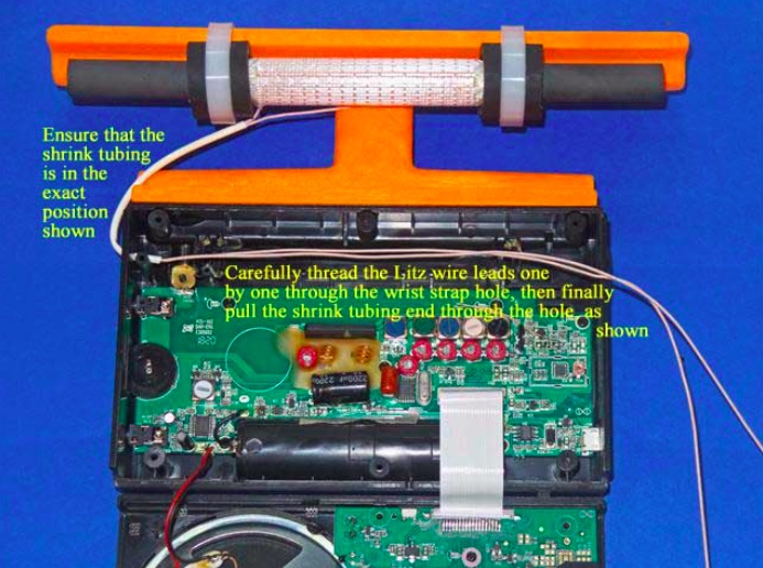
18) Refer to the photo below. Lay the two cabinet sections down flat as shown, ensuring that the Litz wire shrink tubing is in the exact position shown (if it isn’t, carefully slide it along both Litz wires until it is in this exact position). Carefully thread one Litz wire end through the empty wrist strap hole, then thread the other Litz wire end through the hole, as shown. Finally pull on the two Litz wires together from the right while guiding the end of the shrink tubing into the empty wrist strap hole, and pull a short section of the shrink tubing through the hole (as shown) to protect the Litz wire insulation from friction damage.
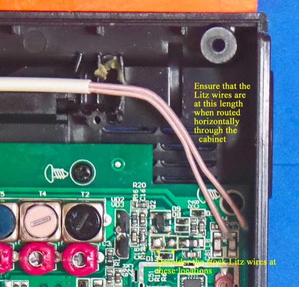
19) Refer to the photo below. Using the previous procedure to install shrink tubing (which is described in the PL-380 transplant article) install a 2.5” (63mm) length of shrink tubing over the two Litz wire ends, and shift the shrink tubing into the position shown in the photo. After this is done cut the two Litz wire leads to the lengths shown in the photo (NOTE: make sure that the ends of both Litz wires are cleanly cut, not frayed and at the minimum diameter before attempting to insert them into the shrink tubing. The process is much easier when the Litz wires pass smoothly through the shrink tubing).
20) Refer to the close up photo below. Using a low heat (25w) pencil-type soldering iron, remove the two stock Litz wire leads at the positions shown, taking care not to use excessive heat, or touch the adjacent components. Ensure that the new Litz wire leads are at the length shown when the leads are in a horizontal position throughout the cabinet, and cut them to this length if they are not.
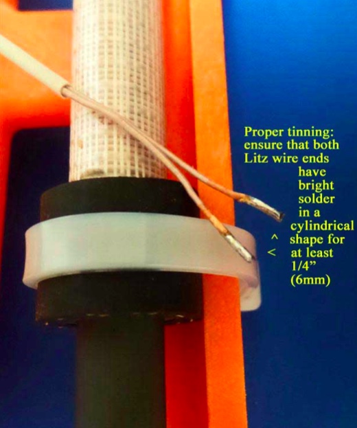
21) NOTE: When tinning the 250/46 Litz wire it is essential that all of the individual Litz wire strands be completely soldered together for a length of at least 1/4” (6mm), with bright, shiny solder around the circumference of the Litz wire ends for this minimum (1/4”) length. The Litz wire must be heated with a clean, hot soldering iron around its circumference in order to melt the solder properly for this step]
Refer to the photo above. Pull the Litz wires up out of the previous position, and place a clean rag underneath them (on top of the circuit board) to completely protect the circuit board from any solder which might accidentally drop down during the tinning process. Using your hot 25w soldering iron melt a generous amount of solder on its tip, and work the soldering iron tip slowly and patiently around the circumference of each Litz wire end until there is a bright, shiny solder length of at least 1/4” (6mm) in a cylindrical pattern at the end of each Litz wire. When doing this, take great care not to allow any solder to drip down onto the circuit board below (i.e., make sure that your rag completely covers the circuit board). The final appearance of your Litz wire lead ends should resemble those in the photo.
22) When your Litz wire lead ends resemble the photo above, cut the soldered portion down to a length of 3/16” (5mm) and observe the appearance of the end of the Litz wire. It should have a bright, solid circular shape, with no gaps or individual Litz wires showing. If not, reheat the end of the Litz wire while adding some solder, and repeat this step.
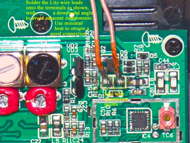
23) NOTE: The Litz wire connection points on the circuit board are surrounded by other important components. It is important to avoid solder drips on these components, or solder bridges to their leads. Solder the Litz wire leads down at an angle to avoid these surrounding components, and use the minimum amount of heat and solder to ensure good electrical connections)
Refer to the close up photo above. Following the precautions described, solder the two Litz wire leads down onto the circuit board at an angle, as shown in the photo. After soldering, make a close visual inspection to ensure that there are no solder bridges across the Litz wire connections, or nearby components. The remaining length of the Litz wire leads should be routed in a horizontal manner to the wrist strap hole.
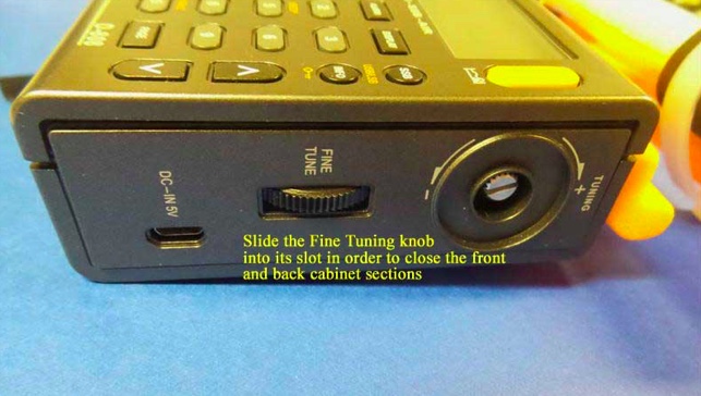
24) Carefully pick up the front and back cabinet sections, and hold the back cabinet section fairly close to the front section (as the radio would normally be oriented, when assembled). Refer to the photo below, and carefully insert the “Fine Tuning” control thumbwheel from the front cabinet section into its slot on the back cabinet section in a sideway movement. This will allow you to fully close the front and back cabinet sections in the next step.
25) Refer to the photo below. Pick up the two cabinet halves and carefully snap them together (this action should not require any great force). Place the radio face down in the position shown (with a soft surface underneath, for protection), and using the Jewelers Phillips screwdriver of the correct size, carefully screw in the six screws that were loosened previously, starting with the screw near the whip antenna post (you should pick up the radio temporarily and hold the two cabinet sections together tightly at this corner, as you do this).
After all six screws have been retightened take the Tuning control knob and press it back onto its shaft in a straight horizontal motion. Finally, reinstall the battery and battery compartment cover to finish up the reassembly.
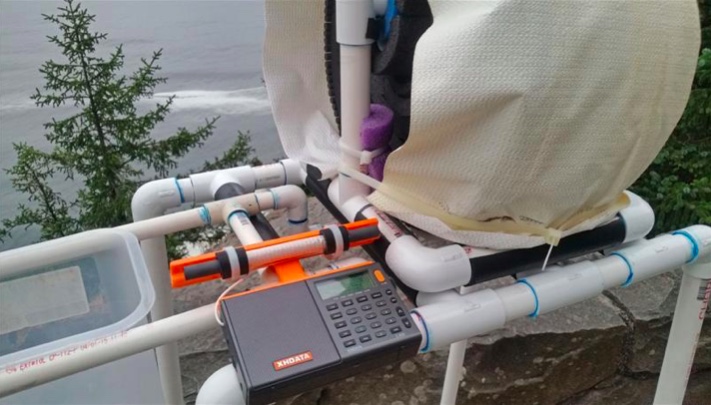
TESTING AND OPERATION– MEDIUM WAVE MODEL
This 7.5” transplant loopstick is designed to provide a major boost in sensitivity from 530-1700 kHz, and if the antenna is working properly both the weak signal reception and the radio’s nulling capability should be greatly enhanced. It is normal for the antenna to receive more background noise on the low band frequencies, although the sensitivity boost should be substantial across the band.
The construction design of the orange antenna frame allows full usage of the whip antenna for checking SW parallels of MW-DX stations, although if you chose to glue the antenna frame flush with the front of the back cabinet surface to simplify the gluing process, you may need to sand the whip antenna slot post slightly to allow free movement of the whip antenna (see step #13).
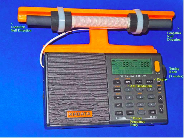
In the photo above, some of the important controls for Medium DXing are highlighted. The AM Bandwidth control allows you to choose multiple DSP filtering selections to enhance selectivity as desired, with the narrowest filtering (1 kHz) providing both the sharpest selectivity and the best weak-signal sensitivity. However this 1 kHz setting also has the poorest audio fidelity, with the higher audio frequencies typically cut off by the DSP filtering. As such, for regular DXing far away from strong local pests, the other AM Bandwidth settings may be more suitable. The Direct Frequency Entry key allows you to manual enter in any MW frequency, to which the radio will shift once the numbers are pressed on the keypad. The Tuning knob has three different modes, which can be toggled by pressing the knob horizontally. The first mode is tuning in either 9 kHz or 10 kHz steps (depending on which of these step you have selected), while the second mode is tuning in 1 kHz steps. The third mode is to lock the frequency in place. Pressing the knob again will return the tuning to 9 or 10 kHz steps.
The XHDATA D-808 has multiple display functions, which can be toggled by the indicated key. The first option is the temperature in either Centigrade or Fahrenheit (depending on your pre-set preference), while the second option is the alarm time. The third option is the current time (which you need to set according whether you prefer UTC or local time), while the fourth option is the received signal strength in both dBu and dB.
The supplied 3.7v lithium ion battery has superior run time, and may be easily charged using the supplied USB cable to either a computer or AC outlet (with the appropriate adapter). As reported in various posts throughout this year, the D-808 model has rugged construction with an excellent record of survival under tough conditions, including hot summer days, moderate rain exposure and extended usage as the main receiver during a 9-day ocean cliff DXpedition in Oregon—performing flawlessly at all times.
Conclusion
It is the author’s sincere hope that this “Supercharged” D-808 model will bring you a lot of DXing fun during travel, as well as at other times. When conditions are good you should never underestimate this enhanced model’s potential of receiving awesome DX beyond your expectations—as an example, here is the stand-alone performance of a 7.5” loopstick D-808 in receiving 1017-A3Z in Nuku’alofa, Tonga (10 kW at 5,632 miles/ 9,063 km) on the ocean cliff near Manzanita, Oregon at 1301 UTC on August 8th of this year:
Not only Tonga is received, but even the Australian horse racing station 1017-2KY in Sydney (5 kW at 7,630 miles/ 12,280 km) is received as a weak co-channel in the middle of the recording. My hope is that you all will be so lucky with your new Supercharged D-808!
73 and Good DX,
Gary DeBock (in Puyallup, WA, USA)
Absolutely amazing! Thank you for taking the time to put this procedure together and describing the process in such fine detail, Gary! Hats off to you!
Click here to read all of Gary DeBock’s posts on the SWLing Post.
Many thanks to SWLing Post contributor, Rich (WD3C), who writes:
Was browsing the Anon-Co site the other day and noticed they are selling replacement rotary encoders for the some Tecsun models.
As I have a PL-660 with a bad encoder decided to order one and replace it. The cost was only $5.95 with free shipping and took about 6 days from Hong Kong.
With a bit of un-soldering the replacement only took about 20 minutes and now works better than new, as the original was always a bit temperamental.
Wow–thank you for pointing this out, Rich! I didn’t realize so many parts were available including knobs, encoders, antennas, back stands and battery doors–essentially, all of the parts that are prone to damage or loss.
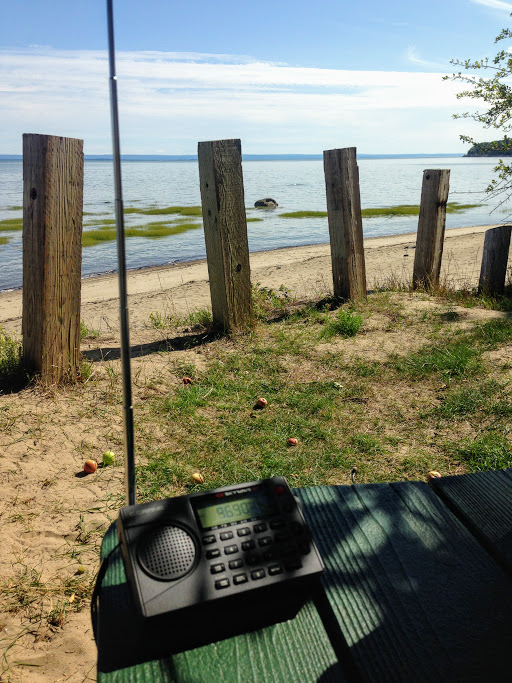
Yesterday, the weather was gorgeous here in Québec, thus a prime opportunity to find a beach, start a new book and, of course, play radio!
I found a fantastic spot on the north bank of the St. Lawrence river near Baie-St-Paul, Québec. There were only a few folks at the beach, so it was all very peaceful.
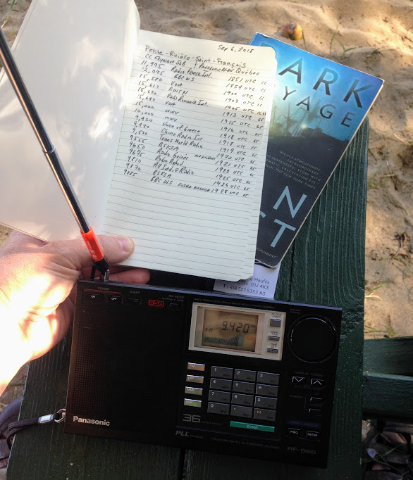
I found a picnic table perched on the edge of the beach shaded by an apple tree–a perfect spot to relax, play radio and start a new book: Dark Voyage by Alan Furst.
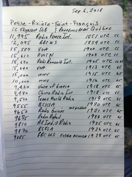
I had not checked to see if propagation was good, but tuning to WWV on 10 MHz and 15 MHz confirmed that signals were travelling. In fact, as I started tuning around–first with the CC Skywave SSB, then with the Panasonic RF-B65–I discovered some of the best propagation I’ve experienced in ages!
I did a relatively quick scan covering the 31 through 19 meter bands. Some signals were absolutely booming in.
I jotted down some of the broadcast details on a make-shift log and recorded a few videos.
Note that after making the first video, I discovered I had limited space on my phone, so most of the clips are quite short:
SDR Primer Part 1: Introduction to SDRs and SDR applications
I author a radio blog known as the SWLing Post; as a result, I receive radio-related queries from my readers on a daily basis. Among the most common questions are these:
“So, what is an SDR, exactly? Are these better than regular radios?”
and/or,
“I think I’d like to buy an SDR. Which one do you recommend?”
Great questions, both! But, before I address them, I must let the reader know that they are also “loaded” questions: simple enough to ask, but quite nuanced when it comes to the answers.
No worries, though; the following three-part primer sets out to address these questions (and many more) as thoroughly as possible. This first part of the primer will focus on the basic components of an SDR system. In part two, next month, we’ll look at affordable SDRs: those costing less than $200 US. In part three, we’ll take a look at pricier models and even include a few transceivers that are based on embedded SDRs.
But before we begin, let’s start with the most basic question: What is a Software Defined Radio (SDR), exactly?
Not your grandpa’s radio
Here’s how Wikipedia defines SDR:
“Software-defined radio (SDR) is a radio communication system where components that have been traditionally implemented in hardware (e.g. mixers, filters, amplifiers, modulators/demodulators, detectors, etc.) are instead implemented by means of software on a personal computer or embedded system.”
Whereas your grandpa’s radio was all hardware––in the form of filters, mixers, amplifiers, and the like––SDRs are a mix of hardware andsoftware. With the exception of tabletop transceivers and receivers with embedded software and systems (which we’ll discuss in part three of our investigation), SDRs typically take on a “black box” appearance: in other words, the radio looks like a simple piece of hardware with a minimum of an antenna port, a data port and many times there’s also some sort of LED or light to let you know when the unit is in operation. On some models of SDRs, there is a separate power port, additional antenna connections, power switch, and possibly some other features; however, “black box” SDRs often look like a nondescript piece of portable computer hardware––something like an external portable hard drive.
Why would you want an SDR?
Many of us have made it through life thus far without an SDR…so, why in the world should we want the use of one? Below, I’ll list some of the most appealing reasons:
Bang-for-buck
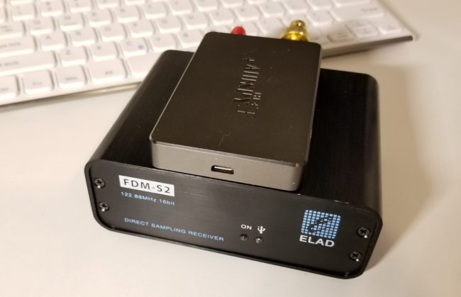
The Airspy HF+ (top) and FDM-S2 (bottom). Photo by Guy Atkins.
By and large, SDRs are quite a value when compared to legacy all-hardware radios. For example, I wouldn’t hesitate to pit my SDRs––such as the $500 Elad FDM-S2 or $900 WinRadio Excalibur––against legacy receivers that cost two to three times their price. Indeed, my $200 AirSpy HF+ SDR will give many DX-grade ham radio general coverage receivers a real run for their money. They’re that good.
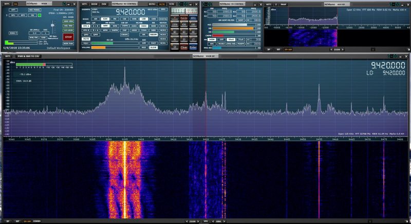
Spectrum display
SDR applications have a spectrum display which gives you a real-time view of a broad swath of the radio dial. Whereas you can tune to and listen to one frequency at a time with legacy receivers, SDRs allow you to view, say, the entire 31 meter band. With the spectrum display, you can see when signals come on or go off the air without actually being tuned in to them. You can tell what signal might be causing interference because you can see the outline of its carrier. Spectrum displays are truly a window––a visual representation––of what’s on the radio. Using legacy receivers now often makes me feel like I’m cruising the bands with blinders on. After becoming accustomed to having a spectrum display, there’s simply no way I’d want to be without at least one SDR in my shack.
Powerful tools
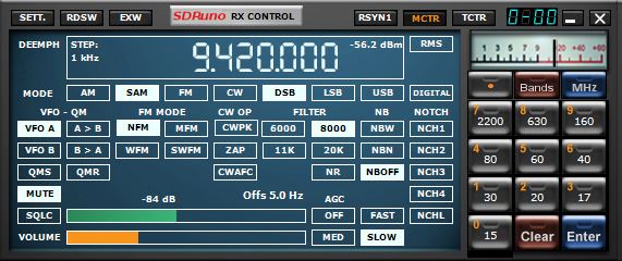
I like how clean the user interface is for this SDR application (SDRuno) window that controls the SDR’s frequency, mode, filters and notch.
SDRs usually afford access to a dizzying array of customizable filters, gain controls, noise blankers, digital signal processing (DSP), audio controls, and more. Being able to customize the SDR’s performance and listening experience is simply unsurpassed. In fact, it’s almost a curse for SDR reviewers like me––comparing two SDRs is problematic because each can be altered so much that identifying the best performance characteristics of one or the other becomes a real challenge. In other words, comparing SDRs is almost like comparing apples to oranges: even using a different application can enhance and thus alter the performance characteristics of an SDR.
Multiple virtual receivers
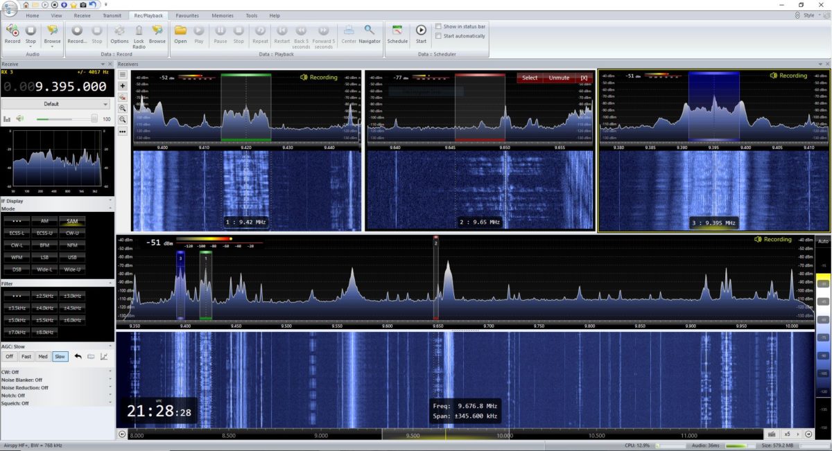
SDR Console makes managing multiple virtual receivers a breeze.
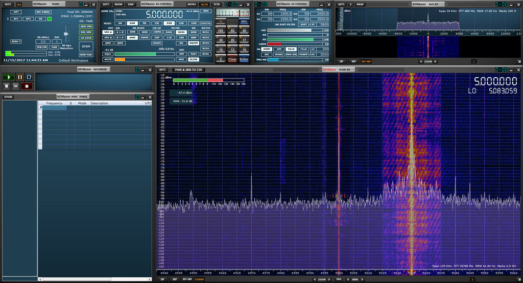
Whereas most legacy tabletop receivers allow you to switch between two VFOs (VFO A and B) some modern SDR applications allow for multiple independent virtual receivers––in essence, multiple sub-receivers. On my WinRadio Excalibur, for example, I can run three fully-functional and independent virtual receivers within a 2 MHz span. On receiver 1, I might be recording a shortwave broadcaster on 7490 kHz. On receiver 2, I might be recording a different broadcaster on 6100 kHz, and following a 40 meter ham radio net on 7200 kHz in the lower sideband.
Recording tools
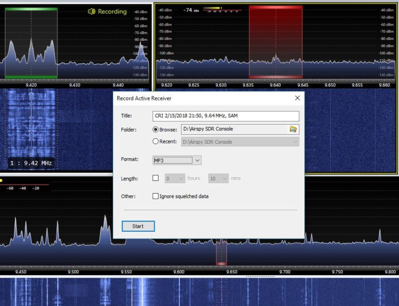
SDR applications, more often than not, have functionality for making audio recordings of what you receive. Some, like the WinRadio Excalibur and SDR Console, actually allow for multiple simultaneous recordings on all of their virtual receivers.
SDR Console recording dialog box
Most SDR applications also allow you to make spectrum recordings, that is, to record not just one individual broadcast from one radio station at a time, but to record an entire broadcast band, all at once. Each recording can easily contain dozens of stations broadcasting simultaneously. Later, you open the recording and play it back through the SDR application. Recordings can be tuned and listened to as if they were live. Indeed, to the SDR application, there is no difference in using an antenna or using a recorded spectrum file; the tuning experience to the listener is also identical.
So imagine that propagation is stellar one evening, or there’s a global pirate radio event just when you’re going to be away from home: simply trigger a spectrum recording and do a little radio time travel tuning later. It’s that easy.
Constant upgrades
Both SDR applications and SDR firmware are upgradable from most manufacturers. In fact, I’ve found that the most affordable SDRs tend to have the most frequent upgrades and updates. Updates can have a positive impact on an SDR’s performance, can add new features, such as the ability to expand the frequency range or more filters or embed time stamps in the spectrum waterfall. It could be pretty much anything and that’s what’s so brilliant. As a user you can make requests; your SDR’s developers might, if they like the idea, be able to implement it.
So, what’s not to love?
Looking at all of these advantages of SDRs over legacy radios, it sounds like SDRs should truly suit everyone. But the reality is, they don’t. For some radio enthusiasts, SDRs do have some unfortunate disadvantages:
First, if you’re primarily a Mac OS or Linux user, and/or prefer one of these platforms, you’ll find you have much less selection in terms of SDRs and applications. While there are a few good applications for each, there are many more SDR applications for PCs operating Windows. Until I moved into the world of SDRs, in fact, I was a Mac OS user outside of work. At the time, there were only one or two SDR applications that ran on the Mac OS––and neither was particularly good. I considered purchasing a copy of Windows for my MacBook, but decided to invest in a tower PC, instead.
Second, one of the great things about legacy radios is that with just a radio, a power source, and an antenna, you’re good to go; travel, field operations, and DXpeditions are quite simple and straightforward. SDRs, on the other hand, require a computer of some sort; when traveling, this is typically a laptop. I’ve spent several summers in an off-grid cabin in Prince Edward Island, Canada. My spot is superb for catching DX, and there’s no RF interference, so I love making spectrum recordings I can listen to later. Problem is, powering so many devices while off-grid is an art. Normally, my laptop can run off of battery power for hours, but when the laptop also provides power to an SDR and portable hard drive, it drains the battery two to three times faster.
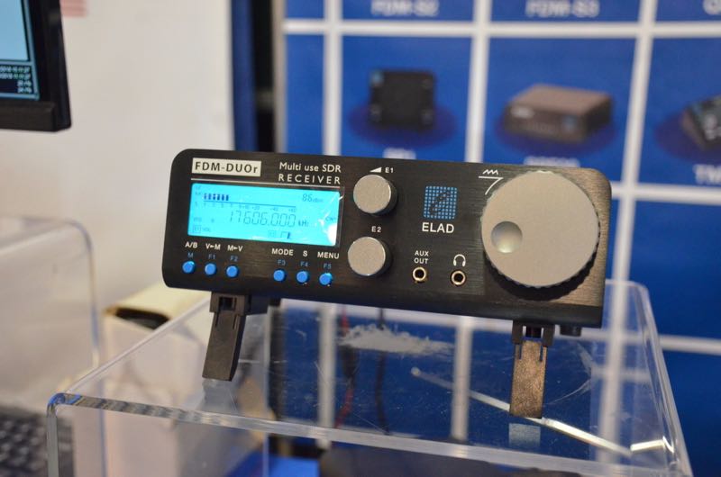
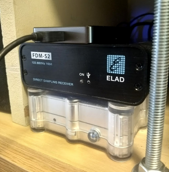
The ELAD FDM-DUOr (receiver).
With this said, keep in mind that there are fully functional tabletop radios (like the Elad FDM-DUO and FDM-DUOr) that are actually SDRs, providing an easy way to bypass this concern.
Finally, there are simply some people who do not care to mix PCs and radio. I’ve a friend who’s a programmer, and when he comes home to play radio and relax, the last thing he wants to do is turn on a computer. I get it––as a former programmer, I used to feel that way myself. But the world of SDRs lured me in…and now I’m a convert.
Scope of this primer series
The world of SDRs is the fastest growing, most dynamic aspect of the radio world. Because of this, I simply can’t include all SDRs currently on the market in this primer. Let’s face it: there are just too many, and it is beyond the scope of this article to try to cover them all. Instead, I’ve curated my list, by no means comprehensive, to include a selection of the most popular and widely-used models.
I’ll be focusing on SDR receivers unless otherwise noted. In Part Three, I’ll call out some popular SDR transceivers. Additionally, I’ll bring my attention to bear on the “black box” variety of SDRs.
This primer is long overdue on my part, so I’ll provide answers to the most frequent questions I receive. But though this primer is in three parts, it barely scratches the surface of the vast world of SDRs.
Thus far we’ve defined an SDR and discussed its advantages and disadvantages.
Now, let’s take a closer look at what you’ll need to build a station around an SDR.
Assembling an SDR station
Guy Atkins’ laptop running HDSDR software in his SUV; the receiver is an Elad FDM-S2. (Photo: Guy Atkins)
In truth, most of you reading this primer will already have everything you need to build a listening post around an SDR. Understanding the components of the system in advance, however, will put you in a better position to get on the air quickly with an SDR that suits your needs best. Let’s discuss this component by component.
A computer
By virtue of reading this primer now being displayed on your screen, unless you’ve printed it out, I’m guessing you have access to a computer of some sort.
SDRs are really quite flexible in terms of computer requirements. SDRs are compatible with:
A desktop PC running the Windows operating system
A laptop PC running the Windows operating system
A desktop Apple computer running MacOS and/or Windows
A laptop Apple computer running MacOS and/or Windows
A tablet or smartphone computer running Android or Windows
A Raspberry Pi/Beaglebone (or similar budget computer) running a Linux distribution
If SDRs are compatible with so many computer operating systems and configurations, then why would you worry about which ones to choose?
As I mentioned earlier most, but not all, of the SDR applications on the market are only compatible with the Windows operating system. If you want the most out-of-the-box, plug-and-play SDR options, then you should plan to use a Windows PC. If you’re a MacOS user, fear not. Modern Apple computers can support Windows—you simply purchase a copy of Windows and set your system to boot as a Windows machine (assuming you have the storage space for a dual boot).
Secondly, processing speed is certainly a factor: the faster, the better. While you can use an Android/Windows tablet or a Raspberry Pi to run an SDR, they often don’t have features like multiple virtual receivers, wideband spectrum recording capabilities, and large fluid waterfall displays due to the simple lack of processing power. My guess is that by 2023, however, tablets and budget computers will have ample processing power to handle most, if not all, SDR functions.
Finally, if you plan to make spectrum recordings, especially wideband ones (2 MHz, plus), you need both a snappy processor and a high-capacity hard drive with a decent write speed. This is the reason I now have a desktop PC at home for spectrum recordings: I can use a very affordable SATA drive as a storage device, and the write speed is always more than adequate. My OS and SDR applications run on an SSD (solid state drive) which is very fast. All of my recordings are saved to internal and external 4TB+ hard drives. Happily, I’ve never had a hiccup with this system.
An SDR application
SDRuno has an attractive user interface comprised of multiple adjustable windows.
Wait a minute…am I suggesting you choose an SDR application before you choose an SDR? Why, yes, I am! You cannot use an SDR without an SDR application, but, with only a few exceptions, you certainly can use an SDR application without an SDR attached.
Unlike a legacy hardware radio, you can essentially test drive an SDR by downloading an application (almost always free) and then downloading a test spectrum file. Most SDR manufacturers will have all of this on their download page. Simply install the application, open the spectrum file, et voila! You’re now test driving the SDR. Your experience will be identical to the person who originally made the spectrum recording.
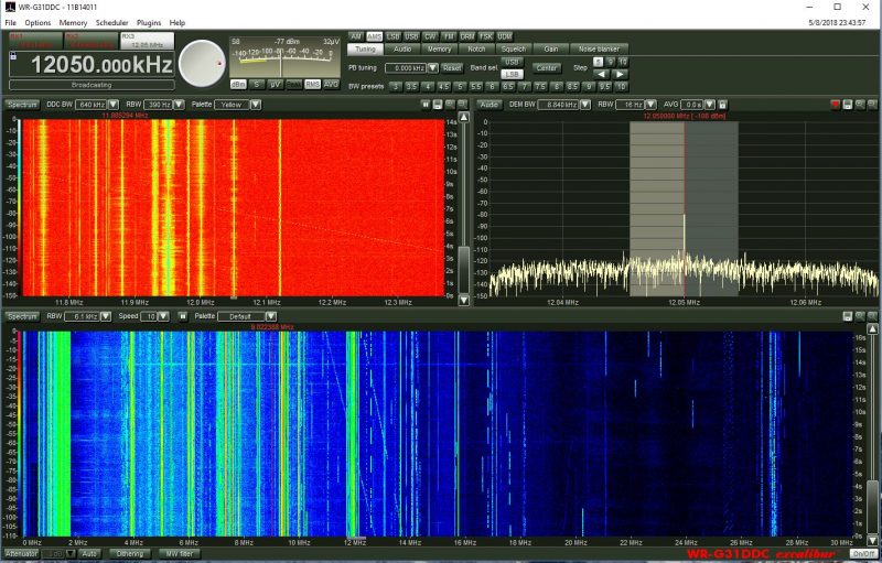
The WinRadio Excalibur application also includes a waterfall display which represents the entire HF band (selectable 30 MHz or 50 MHz in width)
I always suggest test driving an application prior to purchasing an SDR.
While all SDR applications have their own unique layout and menu structure, almost all have the same components, as follows:
a spectrum display, which gives you real-time information about all of the signals within the SDR’s frequency range;
a waterfall display, which is a graphical representation of the signals amplitude or strength across the SDR’s frequency range displayed over time;
filter controls, which help you adjust both audio and signal widths;
mode selections, which allow you to change between modes such as AM, SSB, FM, and digital;
a signal meter, which is typically calibrated and resembles a traditional receiver’s “S” meter;
a frequency display for the active frequency;
VFOs/virtual receivers, which may have real estate allocated on the display;
a clock, which displays the time, possibly as both UTC and local time (note that many SDR apps also embed time code in waterfall display);
memories, where you can store a near-infinite number of frequencies (and some SDR applications allow you to import full-frequency databases); as well as
other controls, such as squelch, gain, noise blanker, DSP, notch,etc.
After you’ve become comfortable with one SDR application, moving to another can be a little disorienting at first, but the learning curve is fairly short simply because most have the same components.
Types of SDR applications
SDR applications usually fit one of three categories: proprietary app, free third-party apps, paid third-party apps, and web browser based apps. (Assume each application runs on Windows unless otherwise noted.) Let’s take a look at each.
Proprietary SDR applications
Proprietary apps are those that are designed by the SDR manufacturer and provide native plug-and-play support for the SDR you choose. Proprietary apps give priority support to their own SDR, but some are compatible with other SDRs––or can, at least, read spectrum recordings from other SDRs. Most popular SDRs have a proprietary application. Here are examples of a few proprietary apps:
WinRadio App for the WinRadio/Radixon line of SDRs
Perseus Software Package for the Microtelecom Perseus
Free third party applications are incredibly popular and some even offer performance and feature advantages over proprietary applications. Third party apps tend not to be associated with any one particular manufacturer––SDR# being a noted exception––and tend to support multiple SDRs. I’m a firm believer in supporting these SDR developers with an appropriate donation if you enjoy using their applications.
HDSDR is a very popular application that supports multiple SDRs and spectrum file formats. The layout is simple and operation straightforward.
SDR Console is a very powerful and popular application. Like HDSDR, it supports multiple popular SDRs. It is my SDR application of choice for making audio and spectrum recordings.
SDR# runs AirSpy SDRs natively, but also supports a number of other receivers including the venerable RTL-SDR dongle.
SDR Touch is a popular SDR application for Android devices (Android)
iSDR is one of the only SDR applications currently available for iOS devices. Its functionality is somewhat limited. There are other SDR applications in the works, but at the moment these are in development stages only. (iOS)
Paid third-party apps
Paid third-party apps represent a tiny fraction of the SDR applications available on the market. Indeed, at time of posting, the only one I know about that’s currently on the market is Studio 1, which has been the choice for those looking for an alternative application to the Microtelecom Perseus Software Package.
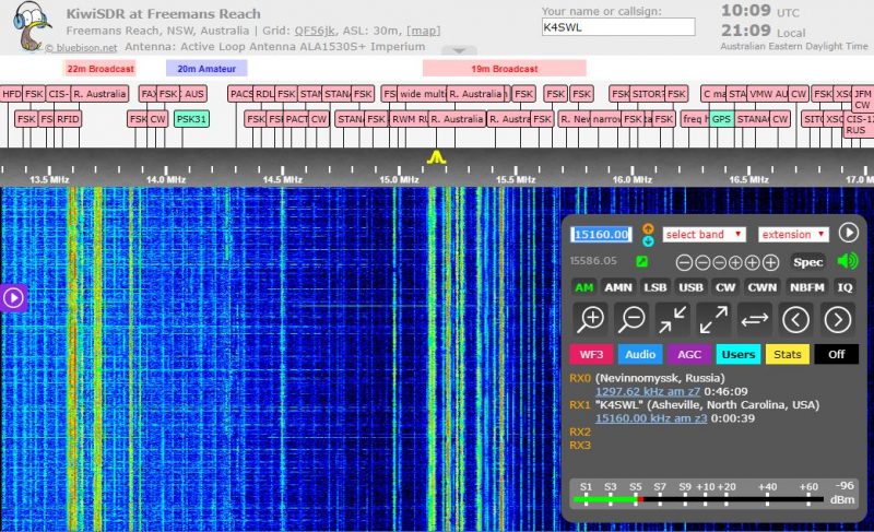
Web browser-based SDR applications
The KiwiSDR browser-based application
This is, perhaps, one of the newest forms of SDR applications. While a number of SDR applications (like SDR#, SDR Console and the Perseus Software package) allow for remote control of the SDR via the Internet, there are actually few applications that are purely web browser-based. At the time of this writing, the only one with which I’m familiar is the KiwiSDR application, which allows both the SDR owner and (if set up to do so) anyone else in the world to operate the SDR as if they are at the SDR’s location. In fact, the KiwiSDR only has a web browser-based application, there is no downloadable application. It will allow up to four simultaneous users, and the experience of using a KiwiSDR locally or globally is nearly identical. If you would like to use a KiwiSDR, simply visit http://SDR.hu or https://sdr.hu/map and choose a remote location.
[Note that if you like web-based SDRs, I highly recommend checking out the University Twente WebSDR located in the Netherlands.]
Choosing an SDR
In Parts Two and Three of this primer, we’ll take a closer look at some of the SDRs currently on the market; prices range anywhere from $15 to $6,000. As you can imagine from such a price range, these are not all created equally.
But first, ask yourself what your goal is with your SDR. Do you want to monitor ham radio traffic? How about aviation communications? Follow pirate radio? Listen to a range of broadcasters? Pursue radio astronomy? Is your dream to set up a remote receiver?
Whatever your flavor of radio, you’ll want to keep some of these needs in mind as you explore the SDR options available to you.
Budget
Be honest with yourself: how much are you willing to spend on an SDR? While entry-level SDRs can be found for anywhere from $15-50 US, a big leap in performance happens around the $100 mark. If you’re looking for benchmark performance, you may need to appropriate $500 or more. Whatever you choose, keep in mind that SDRs are only as good as the antennas you hook up to them. Set aside some of your budget to purchase––or build––an antenna.
Compatible applications
As mentioned above, not all SDRs are compatible with anything beyond the OEM/proprietary application. If you have a choice third-party application in mind, make sure the SDR you choose is compatible with it.
Frequency range
If you want an SDR that covers everything from VLF/longwave up to the microwave frequencies, then you’ll need to seek a wideband SDR. Each SDR manufacturer lists the frequency ranges in their specifications sheet. It’s typically one of the top items listed. Modern wideband SDRs can be pretty phenomenal, but if you never plan to listen to anything above 30 or 50 MHz, for example, then I would advise investing in an SDR that puts an emphasis on HF performance. Check both specifications and user reviews that specifically address performance on the frequencies where you plan to spend the bulk of your time.
Recording and processing bandwidth
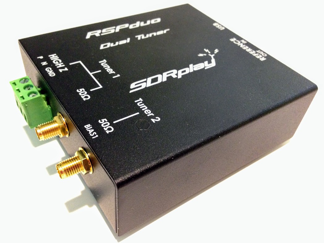
The new SDRplay RSPduo can display up to 10MHz visible bandwidth (single tuner mode) or 2 slices of 2MHz spectrum (dual tuner mode)
If you plan to make either audio or spectrum recordings, or if you plan to monitor multiple virtual receivers, pay careful attention to an SDR’s maximum recording and processing bandwidth. This bandwidth figure is essentially your active window on the spectrum being monitored. Your active virtual receiver frequencies will have to fall within this window, if you’re making simultaneous recordings. In addition, this figure will determine the maximum bandwidth of spectrum recordings. Some budget SDRs are limited to a small window––say 96 kHz or less––while others, like the Elad FDM-S3, can widen enough to include the entire FM broadcast band, roughly 20 MHz!
Portability
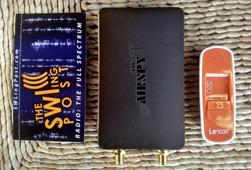
AirSpy’s HF+ was introduced late 2017. Don’t be surprised by its footprint which is similar to a standard business card to its left–this SDR packs serious performance!
If you plan to take your SDR to the field or travel with it, you’ll probably want to choose one that doesn’t require an external power supply. Most late-model SDRs use the USB data cable to power the unit. This means you won’t need to lug an additional power plug/adapter or battery. Still, many professional grade SDRs require an external power supply.
Recording features
If you plan to make spectrum recordings, determine whether you have many options to set the unit’s processing bandwidth. Some SDR applications have robust recording functionality that allows for both spectrum and audio recordings, including advanced scheduling. Some applications don’t even have audio recording or spectrum recording capabilities. Test drive the application in advance to check out their recording functionality. Of course, if recording is your main interest, you’ll also want to set aside some of your budget for digital storage.
Know your goal!
If your goals are somewhat modest––perhaps your budget is quite low, you simply want to familiarize yourself with SDR operation prior to making a bigger purchase, or you only want to build an ADS-B receiver––then you might be able to get by with a $25 SDR dongle. If you plan to use your SDR as a transceiver panadapter during contesting, then you’ll want to invest in a unit that can handle RF-dense environments.
Identify exactly what you’d like out of your SDR, and do your research in advance. Note, too, that many popular SDR models have excellent online forums where you can pitch specific questions about them.
Scoping out the world of SDRs
Three benchmark receivers in one corner of my radio table: The Airspy HF+ (top), Elad FDM-S2 (middle) and WinRadio Excalibur (bottom).
Now that we have a basic grasp on what SDRs are, what components are needed, and what we should research in advance, we’ll look next at some of the SDR options available to us. In Part Two, we’ll look at budget SDRs; those under $200 US in price. In Part Three, we’ll survey higher-end SDR packages.