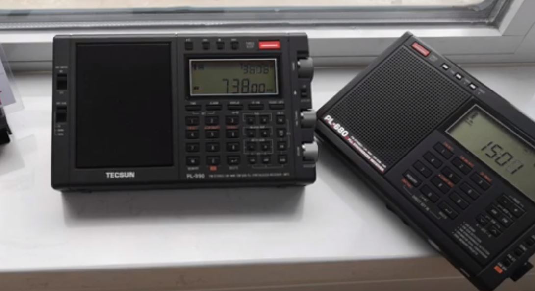
Many thanks to SWLing Post contributor, Steve Lebkuecher, who shares this video which compares the mediumwave performance of the PL-990 and PL-680:
https://youtu.be/m9osecPwiq4

Many thanks to SWLing Post contributor, Steve Lebkuecher, who shares this video which compares the mediumwave performance of the PL-990 and PL-680:
https://youtu.be/m9osecPwiq4
(Source: Radio World)
Is medium wave in decline? Some people think so.
In the 1950s radio was declared mortally wounded by TV. But then FM with its new music rescued it, becoming one of the most successful technologies and platforms ever. Radio survived and thrived but AM should have died at the hands of the nimbler, younger and more attractive FM.
Only it did not and the medium reinvented itself by using presenter-led programming, commercial music and sport. In the United States it took until the end of 1990s for the FM and AM audiences to be equal and to this day the big AM stations are going strong, bringing in the ad dollars.
REASONS
Still, it’s undeniable that the whiff of decline has enveloped AM in the past two decades. The reasons are well-known: Analog medium wave doesn’t always deliver the best sound, it can suffer from interference, it can behave annoyingly different by day and night and even by season. Medium wave mainly appeals to a maturing population (a global phenomenon, considered shameful by some!) using aging receivers (this is bad!).
[…]
THE SOLUTION
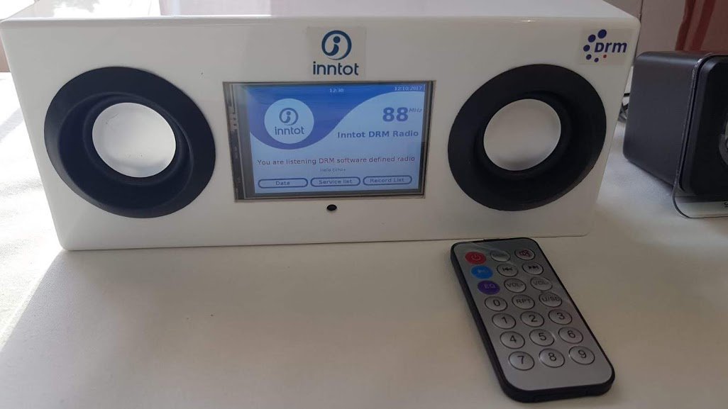
Recently cricket fans were able to enjoy an open-air demonstration of three different DRM programs on one frequency ahead of an important match in Bangalore. The fans also received data (stock exchange values) available on radio screens. This demonstrated that digital DRM is a game changer for medium wave.
In DRM the crackling audio disappears as sound is as good of that on FM. The electricity consumption and costs decrease, the spectrum is trebled and reception, even in cars (as available in over 1.5 million cars in India currently) is excellent, too.
If it is so good then why isn’t DRM medium wave conquering the world faster? Maybe it’s about confidence in a new platform. Broadcasters and governments need to market DRM digital radio once signals are on air in their countries.
As for receiver availability and their costs, let us remember how many receivers were on sale in the 1970s when FM was taking over the world. Nowadays, many listeners consume radio in their cars rather than sit in front of a retro looking wooden box. Digital receivers (DRM alone or DRM/DAB+) are a reality and a bigger push for digital would help with volumes sold thus bringing down the prices.[…]
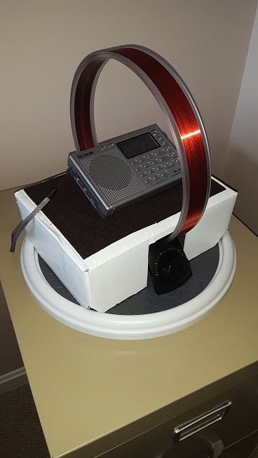
Many thanks to SWLing Post contributor, Rich Stahl (WR3V), who shares his frugal but effective mediumwave DXing setup:
My MWBC directional reception on the cheap (see photo above):
Tecsun PL-310ET $40.85
Tecsun AN200 loop $12.95
Walmart Lazy susan $7.95
Cardboard box -0-Total $61.75
Who says its an expensive hobby?
Indeed! That’s a very basic, yet very effective setup, Bill. Thanks for reminding us that this doesn’t have to be an expensive venture!
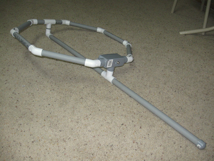
The completed antenna, showing the F-connector on the tee box. (Source: Radio World)
Many thanks to SWLing Post contributor, Kris Partridge, who shares the following antenna construction article from Radio World:
Ken Beckwith is a field engineer with EMF based in Nebraska. Being a hands-on engineer, Ken has done his share of construction over the years. One of his projects was the construction of an octagonal-shaped AM loop EAS antenna using PVC pipe.
[…]The antenna has a broad coverage angle with a deep null when the antenna is broadside to the signal. Aim the “edge” of the loop toward the AM station you want to receive. The strongest signal will be received when the antenna end or edge is pointing to the signal source. The antenna can be mounted on a mast with U-bolts, hose clamps or whatever else works.
Here’s the construction parts list:
A 10-foot length of 3/4-inch diameter, schedule 40 PVC conduit cut into the following lengths:
2 – 4-inch
1 – 2-inch
1 – 2-1/4-inch
2 – 2-1/8-inch
6 – 9-1/2-inch
1 – 23-1/4-inchWhatever is left over can be discarded, but before making your cuts, cut the flared end off, so all cuts are even.
1 – 3/4-inch 90 degree elbow
2 – 3/4-inch tee
8 – 3/4-inch 45 degree elbows
1 – 3/4-inch cap
1 – 3/4-inch tee box, plastic, with weatherproof gasket
1 – 7-foot piece of Belden 8777 or other three-pair shielded cable
3 – 7-foot single-pair shielded cables can substitute for Belden 8777
PVC primer and cement
Wire nuts or other connectors
1 – 3/8-inch ring terminal
F connector barrel with nut[…]
Click here to read the article which contains step-by-step instructions.
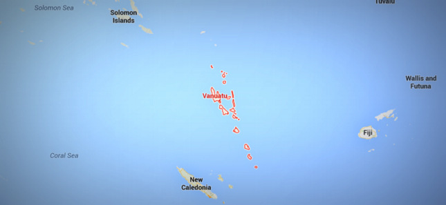
(Source: Vanuatu Broadcasting & Television Corporation via Peter Marks)
RADIO VANUATU CAPITAL DEVELOPMENT WORK BEGINS
With the support of the Government of Vanuatu, the Vanuatu Broadcasting & Television
Corporation (VBTC) has begun work this month on a 942 million vatu (US$8.1m)
infrastructure upgrade to improve radio and free-to-air television service throughout
Vanuatu.The first phase involves the design, installation and commissioning of a new shortwave (HF)
and medium wave (MF) service for Radio Vanuatu, the country’s public radio service. Costing
for phase one will be in excess of 242 million vatu (US$2.2m) and is funded by the
Government of Vanuatu. Following the improvements to shortwave and medium wave
services, VBTC will also undertake technical work to strengthen the coverage and reliability
of its FM services.A 10kw MF Nautel transmitter imported out of Canada and a 10kw HF transmitter
manufactured by Hanjin Electronics of South Korea will be installed at VBTC’s major public
service transmission site at Emten Lagoon on Efate. Both transmitters will be commissioned
before the end of 2019.The second phase, beginning early 2020, will reopen Radio Vanuatu’s medium wave radio
transmission facilities at St Michelle in Luganville on the island of Santo. This will provide AM
service to provinces in the top half of Vanuatu at a cost in excess of 300 million vatu
(US$2.5m).The third phase will expand the national television free-to-air service, Television Blong
Vanuatu, along with a new digital television service. This final phase will cost an estimated
400 million vatu (US$3.5m).Prime Minister Charlot Salwai Tabimasmas launched the capital development upgrade at a
special function attended by cabinet ministers, senior members of the public service,
members of the diplomatic corps and members of Vanuatu’s business and non-profit
communities on Friday September 20 in Port Vila before he departed the country to attend
the UN General Assembly in New York.In his address, the Prime Ministerspoke atlength about the importance to Vanuatu of having
a strong national public radio and television broadcasting service and announced assistance
from Vanuatu’s development partners to help achieve this objective.The Government of Australia funded the scoping study for the radio upgrade project and is
providing funding support to implement the strategic reform programme of VBTC which the
Prime Minister said is making good progress.“I’m also happy to announce that the New Zealand Government is keen to support the
second stage of the Radio Vanuatu technical infrastructure upgrade while China is
considering my request to support the upgrade of Television Blong Vanuatu’s technical
infrastructure.”Meanwhile Kordia New Zealand Limited has been awarded the contract to project manage,
design, install and commission the new radio transmission facilities beginning with the
facilities at Emten Lagoon outside Port Vila.VBTC Chief Executive Officer, Francis Herman said that “Kordia has extensive experience in
the broadcasting and telecommunications industry in the Pacific, and recently completed a
major project in Samoa for State-owned Radio 2AP funded by the Australian Government”.
“We’ve worked hard with Kordia and a number of other technical experts to investigate the
most efficient and sustainable transmission solution for Vanuatu taking into account the
inclement weather, and the need to keep operating costs affordable.”The shortwave service, which will be commissioned before the end of this year, will provide
national radio coverage to the 82 islands spread spanning 1,300 kilometres between the
most northern and southern islands.“Our role as Vanuatu’s national broadcasting service is centered on helping create an
informed public opinion so our people can contribute more effectively to national
development”, Herman added.“VBTC has struggled to remain relevant over the past decade because its technical
infrastructure was obsolete and badly neglected making it challenging for us to provide an
efficient, reliable, and responsive national radio and television service.”Alongside the infrastructure upgrade, is an extensive programme to strengthen the technical
capacity of Vanuatu’s broadcast technicians along with a long-term maintenance regime to
expand the life of the equipment.September 23, 2019
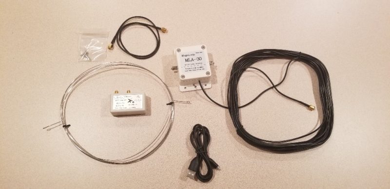
Many thanks to SWLing Post contributor, David Day (N1DAY), who has completed a thorough review of the MLA-30 loop antenna. In this review, he compares the MLA to the Wellbrook ALA1530-LF and a 30 foot square ground loop antenna.
In short, he finds that the MLA-30 performs fairly well on the AM broadcast/mediumwave band, but can’t compete with the Wellbrook otherwise–especially in terms of noise floor. David also noted that “the MLA-30 had a very serious issue with IMD and in some cases, stations that were clearly heard with both the Wellbrook and the ground loop were totally obliterated by IMD when switching to the MLA-30.”.
Click here to read David’s full review on his blog, Ham Signal.
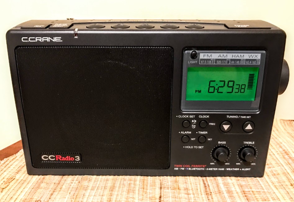
Many thanks to SWLing Post contributor, Steve Lebkuecher, who notes that C. Crane is now shipping the CCRadio3:
Click here to read our review of the CCRadio3—a unit we consider to be one of the best full-sized AM radios currently on the market.