Many thanks to SWLing Post contributor, Andy Webster (G7UHN), who kindly shares the following guest post:
Yaesu FT-817 companion display
by Andy Webster (G7UHN)
Like so many I love getting out portable with my FT-817 but I do seem to spend so much of my operating time fiddling through the soft-keys because my most used functions (CW narrow filter, power and keyer settings to tune an ATU, A/B, A=B, etc.) are spread across different “pages” of the A,B,C assignments. Compared to the sublime experience of using my Elecraft K2 the FT-817 can be a little frustrating!
Last month, inspiration struck and I thought I could cobble together a small microcontroller and a little OLED display with some buttons to provide some extra soft-keys for the radio using the CAT serial port. 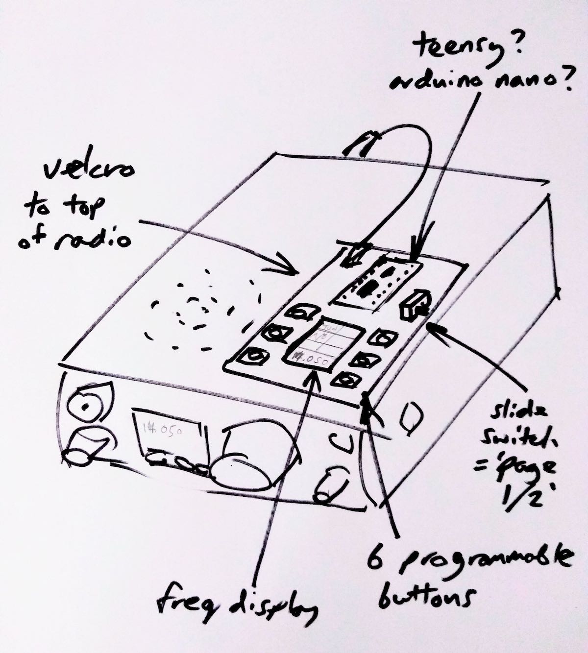 Nothing particularly original here (I’ve seen articles of people using PICs for this purpose) but it seemed like a nice sized project for me to play with and build some experience doing PCBs (I’ve only done this once before at home). A little bit of discussion with Michael G0POT (FT-817 and SOTA guru), some Google searching and we were looking over KA7OEI’s excellent reference page (http://www.ka7oei.com/ft817_meow.html) and thinking about our favourite FT-817 commands…
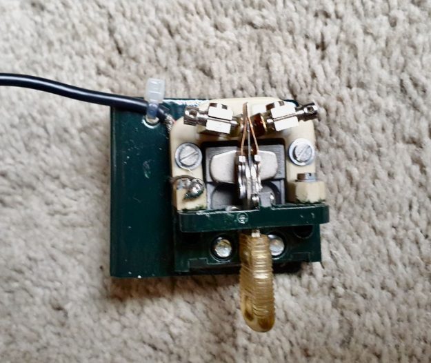
As it happened I was lucky to have the right bits (Arduino Nano, small OLED display, buttons, prototype board and an 8-pin mini DIN cable) lying around the house to see “first light” from my FT-817’s serial port that evening. The Arduino Nano is a good place to start because it works at 5V so can work directly with the FT-817 levels on the ACC port. What followed next was some late nights of hacking on Arduino code to send and receive the data for my favourite commands and more experimentation on prototype board.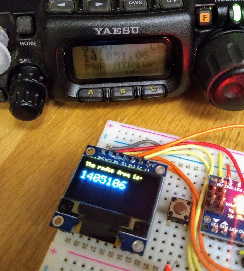
I tried a couple of cheap OLED displays and they look great indoors but weren’t quite up to the job in full sunlight which is fairly typical in my portable operations.
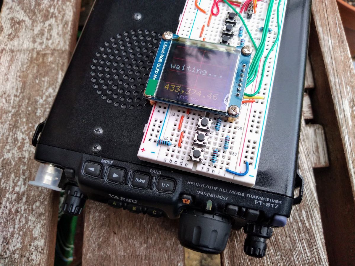
Daytime readability issues with an OLED display
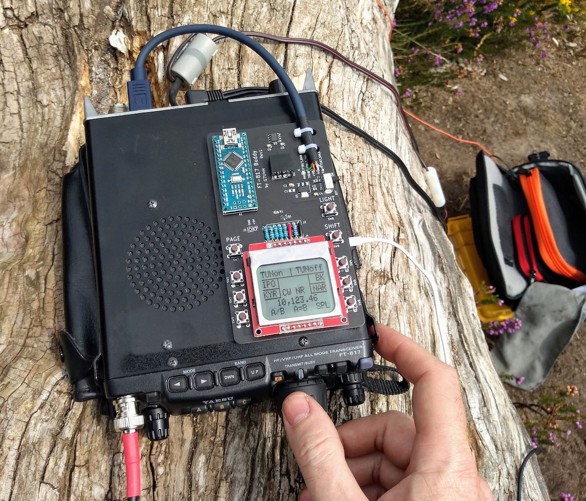
By this point I had also realised the utility of having an auxiliary display on top of the radio as a much easier thing to view than the 817’s own display on the front panel. I’d also experienced some interference from the unshielded prototype board coming through as clicking sounds on the radio’s receiver so it looked as though some isolation between radio and my circuit might be necessary. Guided by many Internet tutorials, I switched to using a Nokia 5110-style LCD for better daylight readability and lower power consumption. Adding an ADUM1201 digital isolator and a B0505S-1W isolated DC-DC converter to the prototype board (modules acquired very quickly from eBay suppliers) gave me some isolation and lowered the interference which I guessed would disappear when I made the design on PCB with good ground planes around the signal lines.
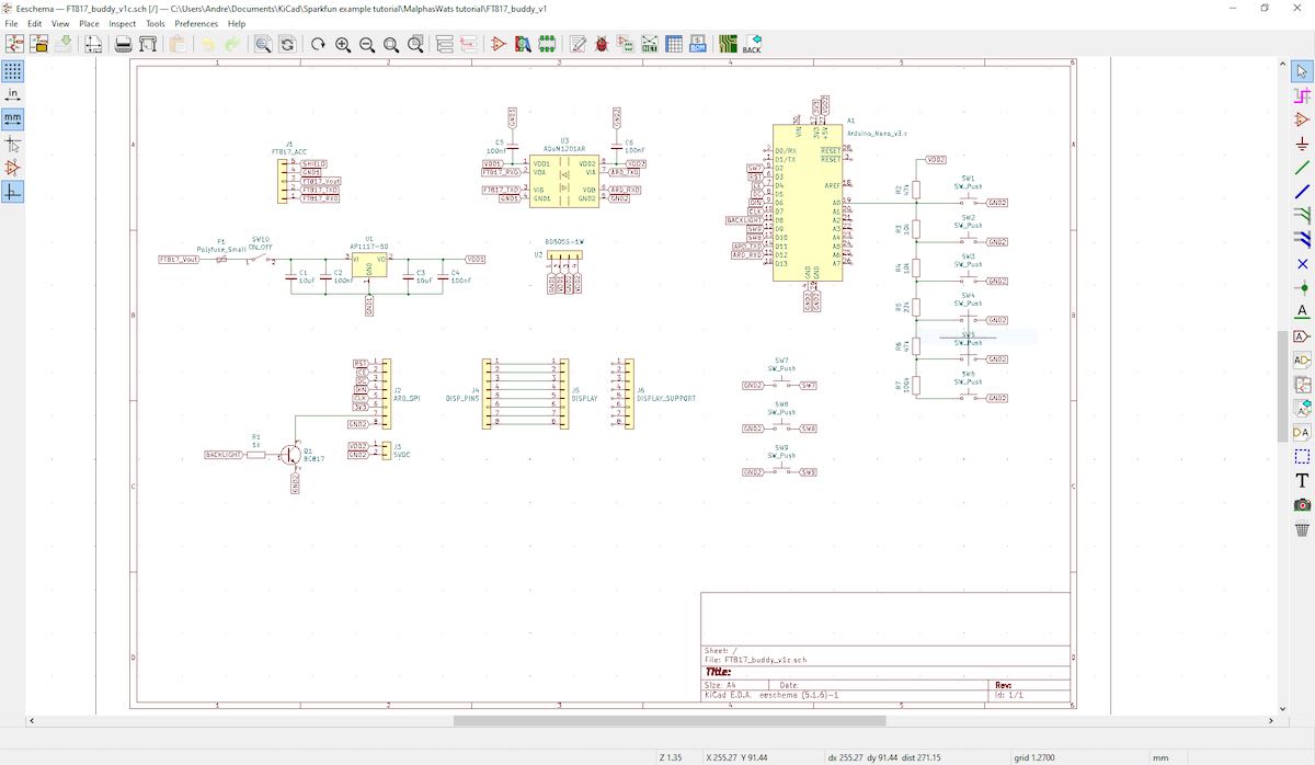
Screen capture showing the schematic (click to enlarge)
With a (mostly) working prototype it was time to hammer the Internet tutorials again, this time to learn how to use KiCad, a free open-source PCB design tool available on Linux, Windows and Mac. I’ve done one PCB for home projects before using Autodesk EAGLE and I found learning Eagle pretty hard going, it seems like it carries 20 years worth of baggage and dogma in the user interface. In fact I started using EAGLE on this project but spent 3 hours on the first evening just trying to change the labels on the ADUM1201 chip that I couldn’t find in an EAGLE library… so I gave up and thought I’d try KiCad which I’d seen some recent good reports on. I’m happy to say after finding an excellent tutorial on KiCad I had drawn the schematic and my PCB layout in about 15 hours working time spread over a few evenings.
I should add that the 15 hours of KiCad time did include several hours of agonising over the choice of slide switch so a PCB can be done much quicker than that once you’ve got your favourite parts sorted!
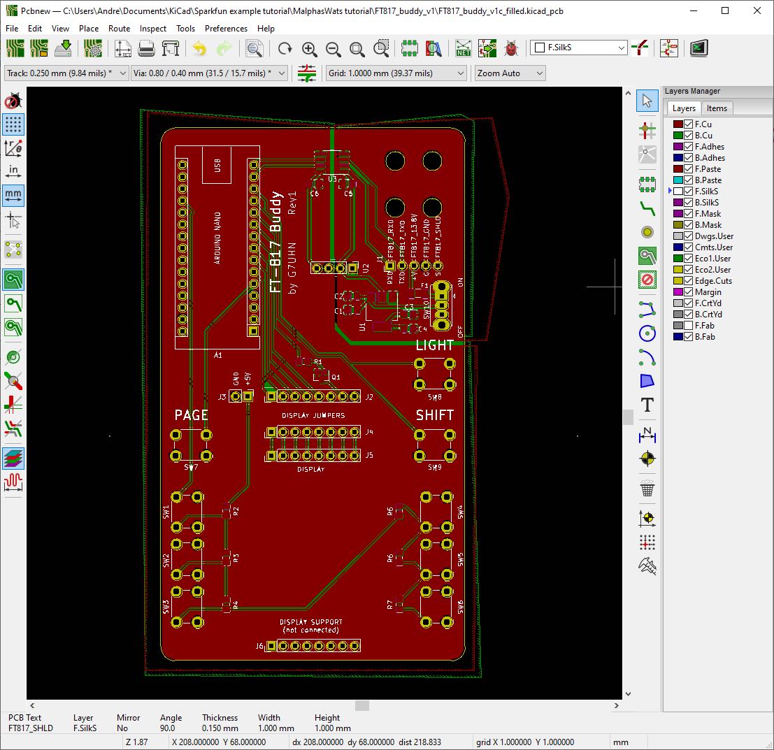
That’s pretty impressive for my first go with KiCad as a near-beginner to PCBs, I heartily recommend it, it was so much easier than EAGLE and quite an enjoyable tool. Right, PCB design done and uploaded to JLCPCB for manufacture. 5 PCBs with DHL shipping cost me less than £20 and arrived from China within 5 calendar days. Other PCB fabs are available… 🙂
Click to enlarge
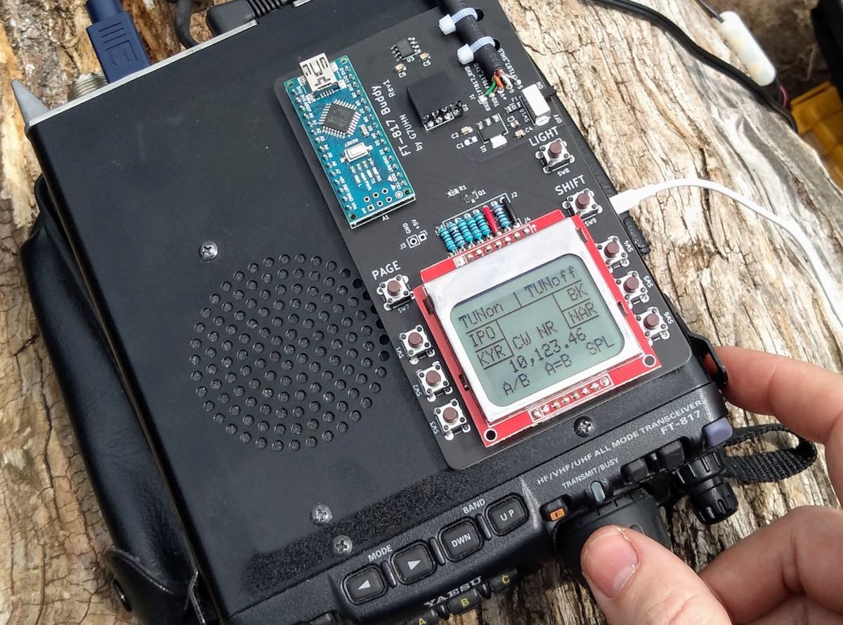
So that brings us to today, pretty much. The PCB was assembled very quickly (!) and there is no sign of noise from the serial data lines creeping into the 817’s receiver now it’s on PCB. Some lessons have been learned through the construction (e.g. brown 6mm push buttons are less “clicky” than the black ones and that’s a good thing!) and I now have my companion FT-817 display/buttons in field trials. I’ve no plans to sell this, it’s a trivially simple design, but it does make a great home project to polish your skills in microcontrollers, PCBs and construction. I’ll post a write-up on my website in due course.
In use, the device works just as I’d hoped, I can do everything I want to on my FT-817 without having to fiddle through the awkward button presses. The frequency display is also in a much better position for me now (as most FT-817 owners will know as they jealously eye the KX2, KX3, etc…!) and I think I used it for the whole session when I took it to the field on Saturday. If only my CW had been so slick!
Next steps are to work on the Arduino code. My code is pretty rubbish (my coding style involves a lot of Stack Overflow and copy/paste!) and not safe for public consumption. There are also some health warnings to be noted in manipulating the FT-817’s EEPROM (required for some of the functions I wanted), explained on KA7OEI’s page but there have been a few volunteers on Twitter to help with the software which is great. Also I may do a “Rev 2” board with an Arduino Pro Mini to lower the drain on the FT-817 battery before sharing the PCB files. Other than that it’s now time to get back outdoors and enjoy the new improved interface to my smallest radio! 😀
73
Andy G7UHN
Andy, I absolutely love this project! A wonderful addition to the FT-817/818 and I’d hardly call it a “trivial” design–!
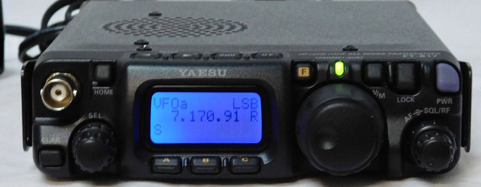
I purchased the original FT-817 shortly after it was introduced. At the time, I was living in the UK and travelled extensively throughout Europe. I loved the ability to simply throw this little rig into my carryon and play radio pretty much anywhere my work travels took me. In the end, I did less ham radio work with the FT-817 and more SWLing.
Still, I eventually sold my FT-817 for the very same reason that motivated you to build a companion display: the front panel is too small and my most used functions require too much menu digging.
Your companion board is an elegant homebrew solution. I love the Nokia LCD screen–superb readability in the field.
Thank you again and once you do a write-up on for your website, we’ll be sure to link to it on the SWLing Post!
Do you enjoy the SWLing Post?
Please consider supporting us via Patreon or our Coffee Fund!
Your support makes articles like this one possible. Thank you!