Shortwave listening and everything radio including reviews, broadcasting, ham radio, field operation, DXing, maker kits, travel, emergency gear, events, and more
Many thanks to SWLing Post contributor, David Day (N1DAY), for sharing the following guest post:
Crystal Radios – Construction, Listening, and Contesting
By David Day – N1DAY
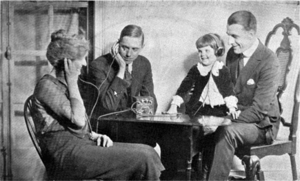
The date was November 2, 1920 and the world was about to change forever when radio station KDKA out of Pittsburgh PA made its first broadcast of election results from the 1920 presidential election. For the first time in history people knew who won the election before reading about it the next day in the newspaper. Radio had arrived!
However, hearing the election results was not as easy as powering up an AM radio receiver because radio electron tubes had only been invented a few years earlier and they were still too expensive for most people to afford in a radio set. After KDKA’s historic broadcast, large 50,000 watt stations began popping up in all major cities around the world. Even though a tube-driven radio was not yet commonplace, many people listened to these stations on their crystal radios. The frenzy around radio in the 1920’s was not unlike the excitement around cell phones and the internet today. If you didn’t have one, you were simply living in the past.
A family listening to a crystal radio in the 1920’s
Fortunately, in the early 1920’s the crystal radio had been around for a while and it was easy to make or purchase a completed set on a limited budget. The beauty of the radio was that it was a passive device needing no power source other than the radio station’s broadcast that was received by a good antenna about 50 feet long and 15 or so feet above the ground. Crystal radios derived their name from use of galena crystals as detectors. Continue reading →
Many thanks to SWLing Post contributor and political cartoonist, Carlos Latuff, who shares the following guest post:
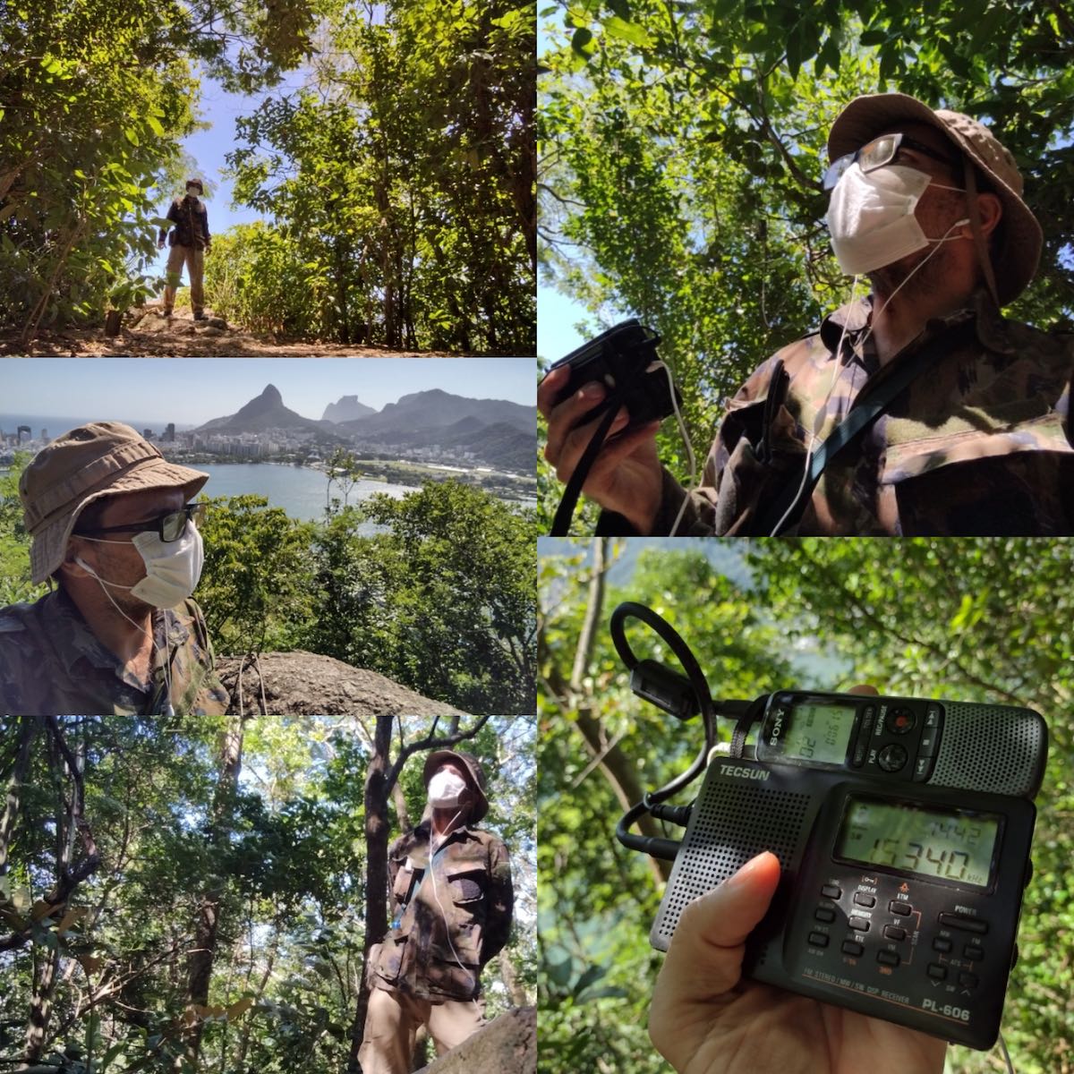
Carlos Latuff at Catacumba Park in Rio de Janeiro, monitoring Ethiopian broadcasts.
ETHIOPIA: A WAR THROUGH RADIO
by Carlos Latuff, special for The SWLing Post
We just entered 2022 and the civil war in Ethiopia has already completed 1 year. On the one hand we have the Tigray People’s Liberation Front (TPLF) guerrillas from northern Ethiopia and its allies, and on the other hand we have the armed forces of Ethiopian government and its allies. The dead are piling up, accusations of war crimes from both sides, local and international political interests at stake, and no perspective for a peaceful solution. Without going into the reasons for this new war in Ethiopian territory, I’d like to focus on the use of radio waves by both parties of this conflict.
I monitored shortwave broadcasts from Ethiopia and to Ethiopia between October 21, 2021 and January 4, 2022. The receivers were Tecsun PL-606 and XHDATA D-808, using both the telescopic antenna and a long wire. In all cases, listening was carried out in Brazilian cities.
Carlos at Catacumba Park monitoring and recording clandestine Ethiopian broadcasts.
Many thanks to SWLing Post contributor, Pavel Kraus, for the following guest post:
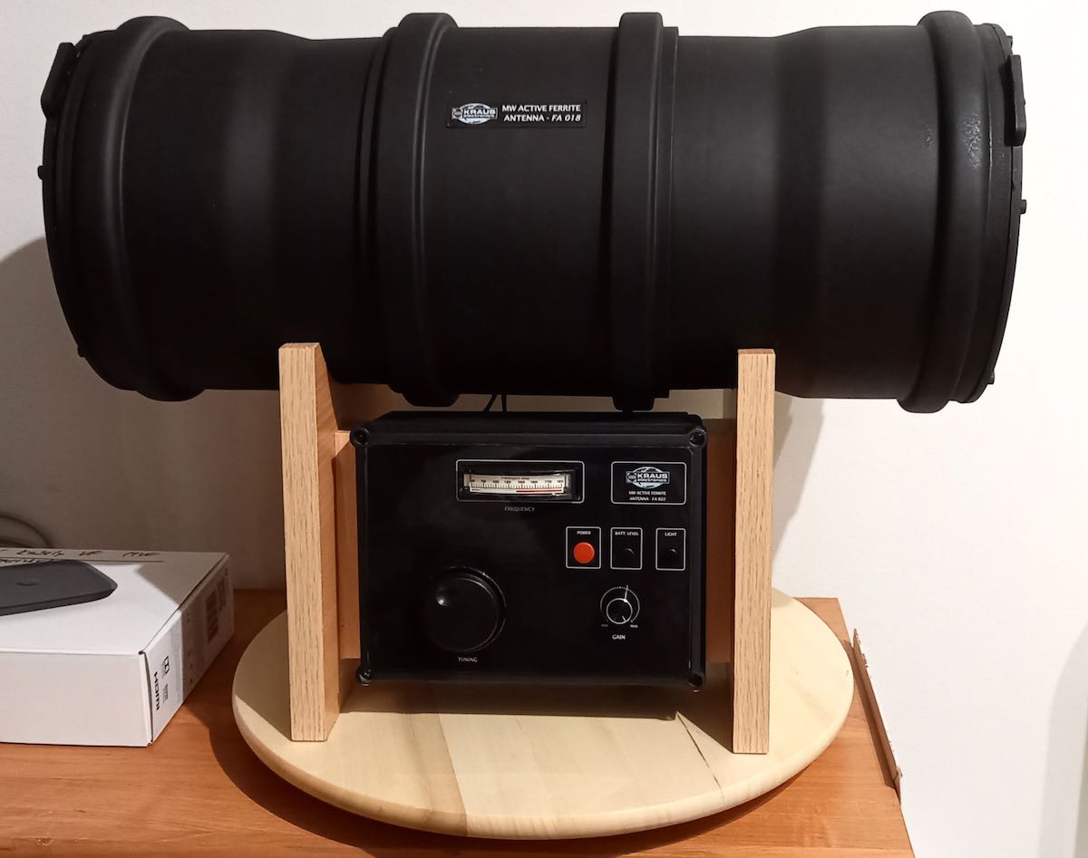
Building a Drain Pipe FSL Antenna
by Pavel Kraus
Hi, I greet all DX fans and the entire SWLing Post community! I enjoy reading reading this blog and the diversity of contributions from our authors and contributors; many thanks from me for so much useful information.
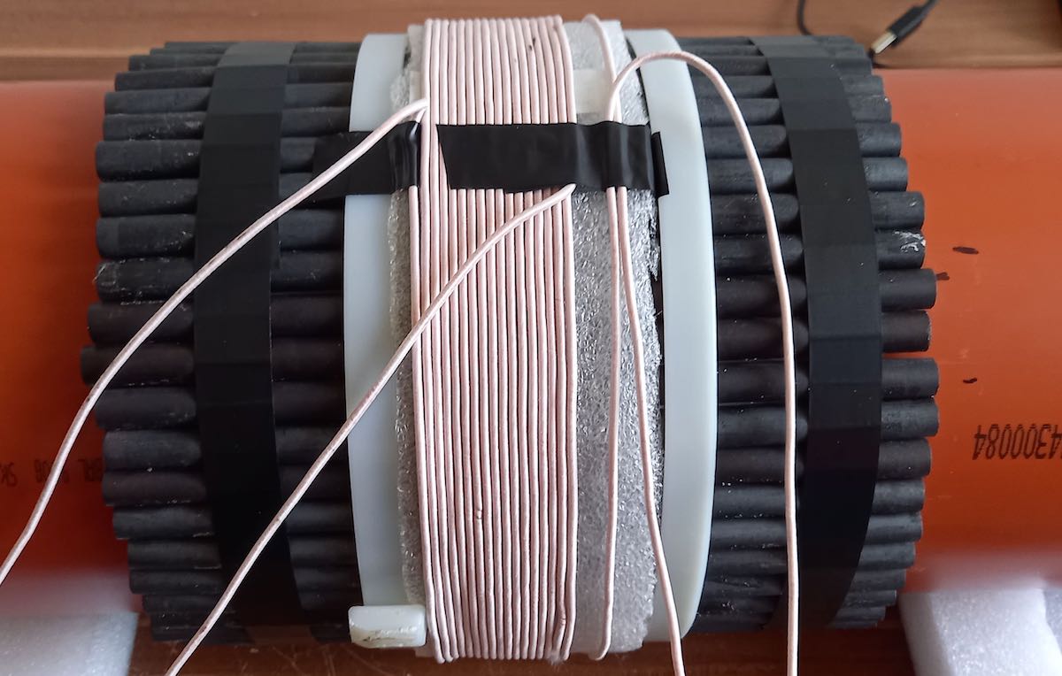
The following are the construction notes of my FSL antenna, which I designed thanks to the suggestions of GaryDeBock, and other FSL designers.
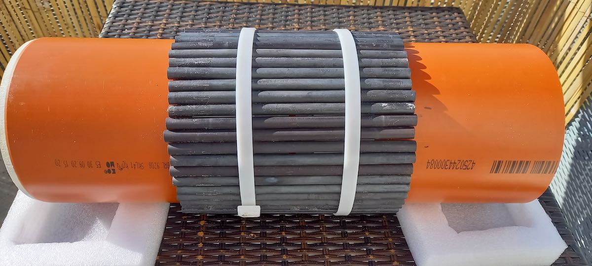
The antenna is a classic design featuring 60 ferrite rods 200x 10 mm, which are placed on a plastic sewage pipe.
Pict 3: Pipe with ferrite rods and windings
Pict 4: Pipe with ferrite rods and windings
In addition, sewer pipe sections are used for the entire antenna cover. I assume that this material can be obtained in other countries as well. Continue reading →
Many thanks to SWLing Post contributor, 13dka, who shares the following guest post:
In search of benchmark signals: The International Beacon Project
by 13dka
If you – like yours truly – like to tinker with antennas and radios to get the most out of them, you likely have your own set of reference stations. If this is a new concept for you – reference stations are whatever stations you deem apt to check propagation, the general function of your radio, when trying to improve reception or comparing radios… They are ideally always on when you need them and come in various strengths and distances on several bands from all over the world. Traditional sources for that are of course time signals and VOLMET stations on HF, even though the latter are giving you only two 5-minute slots per hour for testing reception from a specific region and the former have their own specialities here in Europe:
A typical scene on 10 MHz, captured at home 30 minutes after the full hour: BPM voice ID from China mixed with something else, then Italcable Italy kicks in on top of some faint murmur possibly from Ft. Collins, in winter some South American time stations may stack up on that together with splatter from RWM 4 kHz lower…
A reliable source of grassroots weak signals is particularly desirable for me because I enjoy proving and comparing the practical performance of radios at “the dike”, a QRM-free place on the German North Sea coast. In the absence of manmade noise and the presence of an ocean adding 10dB of antenna gain, finding benchmark stations with “grassroots” signal levels turned out to be a different challenge than it used to be: With somewhat sizeable antennas the stations tend to be (too) loud there, even with the baseline ionospheric conditions under a spotless sun in its activity minimum. In short, my old benchmark stations didn’t work so well anymore and I had to find something new. Continue reading →
Many thanks to SWLing Post contributor, Bill Hemphill, who shares the following guest post:
Simple Android Database-PART 2
by Billy Hemphill, WD9EQD
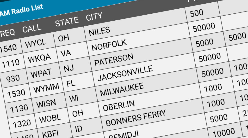
In the first part, I showed how you could easily take a spreadsheet and create a simple database for viewing on an Android phone/tablet. The examples used in that article was two spreadsheets of radio schedules – one for Shortwave and one for FM Radio Programs. See the following link to the original article: https://swling.com/blog/2021/10/guest-post-radio-schedules-in-a-simple-android-database/
There are many lists on the internet of various radio databases. If the database can be downloaded as either a CVS file or a spreadsheet, then it is possible to load it into the PortoDB app on the phone tablet. I’ll show how this can be done with two popular databases that I reference all the time.
EIBI Data Base
Most of you are probably familiar with the EIBI database of shortwave schedules. Many of the Shortwave Schedule apps on the Phones reference this database. For example, I use the Skywave Schedules on my phone. While it does allow for me to search by many parameters, I thought it might be fun to have it in a PortoDB database. Plus it would be interesting to see how PortoDB performs with a large data set. Continue reading →
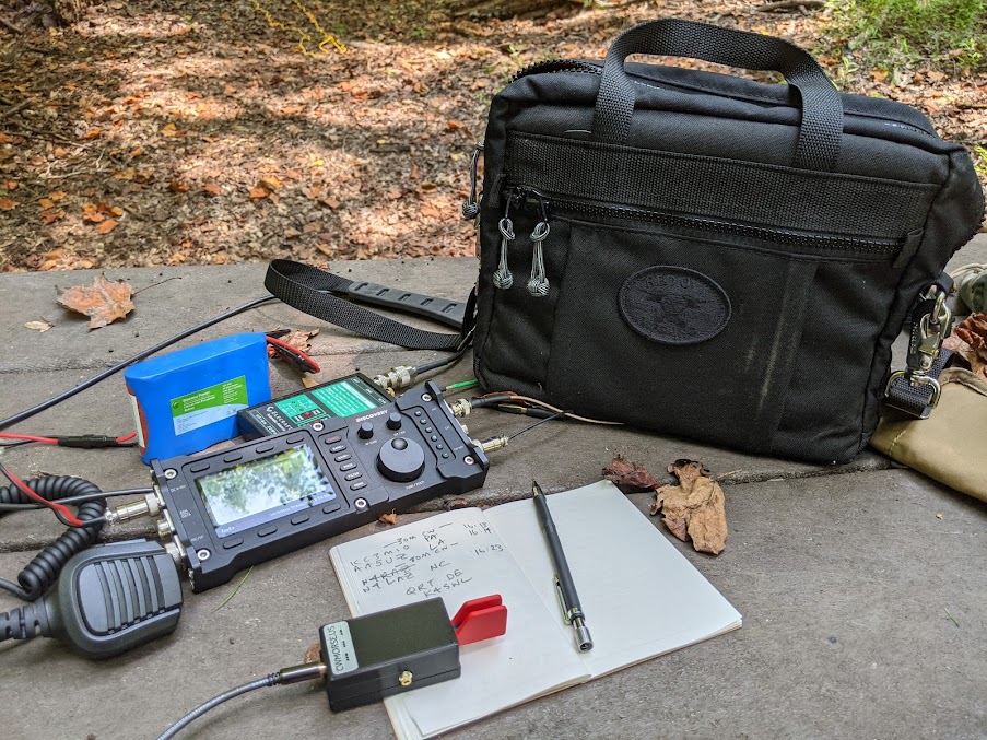
If interested, I’ve now published both parts of my Anatomy of a Field Radio Kit series over on QRPer.com. This series was originally featured in the June and July 2021 issues of The Spectrum Monitor magazine. Here are links to both articles:
These articles primarily focuses on portable amateur radio field kits, but many of the concepts are ones I also use for my field portable receiving setups like this one.
Many thanks to SWLing Post contributor, Dan Robinson, for the following guest post:
Test Driving The Russia-Made Malahit DSP-2
Poised on Edge of Greatness? (Some Challenges To Overcome)
by Dan Robinson
By now, the Malahit SDR is well known in listening hobby circles. We have the made-in-Russia original, and those manufactured in China with various firmware and some physical differences such as location of the tuning encoders.
At the same time, we saw the development and appearance of the Belarusian Belka SDR. I consider the latest Belka DX to be the ideal portable – a sensitive diminutive miracle that has become a must-have device for many of us.
As for the Afedri LAN-IQ, I held off on purchasing one until the “Standalone” version was available. It is made in Israel by a Russian developer who supports the receiver with fairly frequent firmware revisions (though upgrading remains a bit of a challenge involving some obscure boot-loading software).
I waited and observed reviews of the original versions of the Malahit. When its designer, Georgiy (RX9CIM), announced availability of the new DSP-2 version of the receiver, with expanded coverage to 2 GHz and a claim of improved performance, I finally purchased one.
As was observed in one of the early SWLing Post articles “It seem[ed] the project is open source, the schematic, PCB and software are available to download. . . we hope [these] receivers become popular and available world wide [and that] this new project “shakes” a bit the industry of shortwave receivers.”
Malahit project authors RX9CIM George, R6DAN Vladimir, and R6DCY Vadim, had the apparent objective of “designing a low-cost portable SDR radio, using only easily obtainable components and to become the natural successor of the popular Degen and Tecsun radios.”
At the time, the price for a finished Malahit, with an ARM chip at its center was about $195 US. Coverage was to 1 GHz – this has since been extended to 2 GHz. Synchronous AM mode was added, and the DSP-2 also comes with an internal battery tray for a single 18650 Li-on battery.
This is a change from the original flat Li-on cell, and in my opinion a welcome one since 18650s are easily obtainable. Being able to easily change out a battery is important, rather than messing around with soldering (the famous Reuter Pocket receiver made in Germany should take a hint).
In this age of the SDR, we’re all familiar with the SDRplay series and various AirSpy receivers, along with other SDRs such as the RX666/888. Before that, we had the famous Perseus, which still has a strong following, and numerous WinRadio receivers.
See the articles here on the SWLing Post assessing the performance of these, as well as reviews at eHam.net, and numerous SDR dongles all over eBay, coming from China. There is also an SDR group on Groups.io.
Of course, receivers and transceivers with panoramic displays began to appear some years ago – the ICOM IC-R8600 and IC-7300 are examples of how this technology was integrated into the listening and amateur radio markets.
What we had not seen was integration of this kind of technology into portables. Even in its latest iteration, the Belka DX has a small screen without any PAN display. So, the advent of the Malahit has made this kind of advanced display widely available.
The price, by the way, for my DSP-2 as of July 2021 was 19,500 Russian rubles, with an extra 2,000 rubles for express delivery via Russian Post (though due to COVID Georgiy stressed that no guarantees could be made as to timing). That’s $263 – not a small investment and rivaling the cost of a Tecsun ATS-909x and H-501x.
According to the description I received when ordering, the Malahit DSP-2 was improved over the previous version with the following differences:
Frequency range – from 50 kHz to 380 MHz, and 400 MHz to 2 GHz
Improved RF shielding and hardware improvements to reduce interference
Changes in software functions
Dimensions changed to 140x 88x 39mm
18650 battery
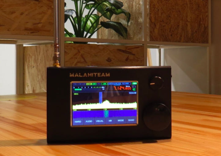
The DSP-2 is in a thin black metal cabinet with dimensions 5 x ½ by 3 x ½ by 1 x ½.
A power button and headphone jack are on the right along with a power LED. On the top, we find the SMA antenna input, and a small telescopic whip is included.
The speaker, capable of some decent audio, is located on the inside rear of the receiver – audio level exceeds that of the Belka DX with its very small speaker, but the Belka has a clarity that often exceeds the Malahit.
My first testing of the DSP-2 was indoors, in a far corner on the top floor of my home, using just the included whip antenna. For comparisons, I used a Tecsun PL-368 with its whip antenna and a Belka DX in the same location. I find that indoor testing tends to identify some issues that would not be apparent outdoors.
In this, the Tecsun PL-368 and other Tecsun portables consistently performed best, followed by the Belka DX and the Malahit. This may be surprising, but shows that radios specifically designed for shortwave reception, often provide better reception because they are matched better with their internal telescopic antennas.
Now, when I say “best” I mean best basic audio quality, using auto-memory and ETM functions on the PL-368 and 990x. But what those radios can do with the signal after that point is pretty limited – there is no NR (noise reduction), you’re limited to a handful of set bandwidth selections, and SYNC mode leaves much to be desired.
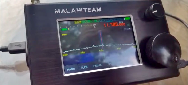
Which is where the Malahit comes in with its numerous levels of flexibility, accessed through MENU icons on the lower part of the screen: HARD, AUDIO, VISUAL, NR, MODE, and BAND. I refer the reader to the Malahitteam site links showing the user manual (this is still a bit in the rough, with translation from Russian) and another link with a Quick Start guide written by John Pitz (KD8CIV).
KEY HIGH POINTS ON MALAHIT
SUPERIOR COLOR DISPLAY
The color display, also seen on numerous China-made clones, is the best on any handheld SDR. Where the Belka LCD is a basic utilitarian tool that performs well for that receiver, the Malahit display is an invitation to the wonderland of what this receiver offers.
At the top are small icons for: SQ, NB, NR, AGC, ANT, PRE, MODE. Right of center, and controlled with pushes of the small volume encoder knob, are ATT, VOL, FILTER, and the battery icon. Below those are headphone and speaker icons and an excellent, if small, frequency window. Pushing the small encoder knob selects/controls volume, attenuation, and main filters. The large tuning knob, with a press, selects step increments.
EXCELLENT NOISE REDUCTION
Noise reduction on the Malahit is superb, as many users have observed. It’s activated directly with a front panel icon and Threshold is adjustable with an icon under AUDIO, with 0 to 30 increments. NR is so good that I compare it with the latest firmware version on the ICOM IC-R8600 – it’s actually probably better than the ICOM even near and at the highest 30 level.
EXCELLENT FILTERING
Whereas the Belka DX offers fixed audio filtering values accessible via its front panel, the Malahit DSP-2 offers continually variable LOW FREQUENCY adjustment from 0 Hz to 2350 Hz, and HIGH FREQUENCY adjustment from 100 Hz all the way up to 150,000 Hz. This is in addition to standard NARROW, NORMAL, and WIDE filter options selectable with the volume encoder knob. This is nothing short of extraordinary for a handheld portable receiver.
The latest (and possibly last) Tecsun receivers offer set value multiple bandwidths, which is excellent but is a throwback to radio design from years ago. So, the DSP-2 capabilities can be compared to the kind of filtering that a Watkins Johnson or Cubic receiver have, but in the palm of your hand.
As I often observe, what we would have given in gold to have this kind of capability in consumer receivers during the glory days of international broadcasting!
AGC / MGC FLEXIBILITY
The Malahit allows the listener to use AGC, with choices of SLOW, MEDIUM, and FAST. But it also allows, again through the AUDIO settings menu, control of AGC GAIN 0 to 60, and AGC LIMITER 40 to 90 db. Wow – priceless! So even if you prefer, as I do, to listen to shortwave using AGC, you still have amazing flexibility. You can still switch to MGC with 0 to 60 range.
NOISE BLANKER FLEXIBILITY
Just as the Malahit delivers on AGC, so does it deliver with its regular noise blanker function. With NB activated, there are 3 configurations with a separate THRESHOLD icon adjustable for each of these. Amazing.
RF GAIN FLEXIBILITY
RF GAIN is adjustable from 0 to 59, and there is a separate icon for adjusting gain for the PRE-AMPLIFIER. Where the PREAMP comes in very handy is when one has the Malahit indoors – it provides a more sensitivity in situations where one is using the telescopic whip antenna, though care must still be taken not to overload the receiver and distort signals.
FCORRECT FUNCTION MAKES FOR EASY RE-CALIBRATION
The Fcorrect function located under the HARD settings menu enables one to re-calibrate the receiver to correct for error. This is similar to the capability that Tecsun added to its 330, 909x and 501x receivers (there are indications Tecsun has or will enable this ability also in the PL-368) but seems, based on my testing of the Malahit to be more effective. After I corrected my DSP-2 to about +57, calibration was pretty much on the money up and down the HF bands.
SQUELCH FLEXIBLITY
The Malahit not only has SQUELCH, but SQUELCH THRESHOLD control, another example of the tremendous flexibility in this receiver’s firmware. Since I do not do much listening outside of the HF bands, or have the antenna for it, I have not extensively tested the Squelch above 30 MHz and up to the maximum range at 2 GHz.
There is yet another feature described as adaptive noise canceling that allows the user to significantly improve the intelligibility of the received station under conditions noise and interference.
[From the manual]: The squelch uses different algorithms [depending] on filter bandwidth. With a bandwidth of more than 1 kHz, a squelch of more than suitable for speech type signal. With bandwidth less than or equal to 1 kHz, the squelch is suitable for tone type signals. Choice of algorithm is carried out automatically, depending on bandwidth. Meanwhile, squelch for speech signals can be used with NR (see further details on this in the manual).
FM RECEPTION WITH RDS
What the Belka DX lacks, namely reception of the FM range, the Malahit delivers in droves. FM sounds excellent to me, on the same level perhaps of the Afedri LAN-IQ Standalone receiver.
RDS is enabled by touching the waterfall area of the display which brings up the RDS information. The speed with which station information appears varies depends on position of your antenna and signal level.
As one user (Harold Hermanns) on the Facebook Malahit group observed: “ I don’t think it works very well. I just checked mine, and went to about 25 stations. The RDS or station name came up on only 5 stations. Letters I get are PS, PT, and PTY. When you tune a strong station, give it a minute or so, that’s what I did, and the RDS feature does work, but again, it’s not 100%. Maybe will be improved with firmware?”
The RDS information could be better organized – currently the name of the station, and name of the program scrolls on different lines. Another touch of the screen brings up an old style FM scale – this is nice, but I prefer the PAN display. Yet another touch returns the screen to the PAN display and waterfall. Mode options include NFM and WFM, and another option provides FM-STEREO. Also in FM, there is an auto-search function and station labeling
MISCELLANEOUS FEATURES
There are some other features in the mind-boggling list of options in various menus:
In FM (WFM) there is an eight position EQUALIZER function with SOFT, LIVE, CLUB, ROCK, BASS, JAZZ, POP, and VOICE positions.
A voltage monitoring function allows the user to turn off the receiver when voltage drops lower than 3.3 volts. As explained in the manual this is intended to preserve battery life and avoid full discharge.
Antenna selection can be 50 ohms or Hi-Z (preferred for telescopic antenna use).
As the Malahit manual details, internal gain of the receiving chip can be adjusted. Accessed from the HARD menu, this is too much for me to go into here, but it’s another example of the detail that went into designing the Malahit.
Brightness of the display backlight is adjustable as well as time after which backlight level is reduced to minimum and turned off completely. Rate of change of the display spectrum is adjustable as is spectrum display range, color, ratio of waterfall and speed and brightness of waterfall. Spectrum scale and view are adjustable.
There is a 5 page memory system, with M1 to M10 in each, so a total of 50 storable memories.
LOW POINTS OF THE MALAHIT
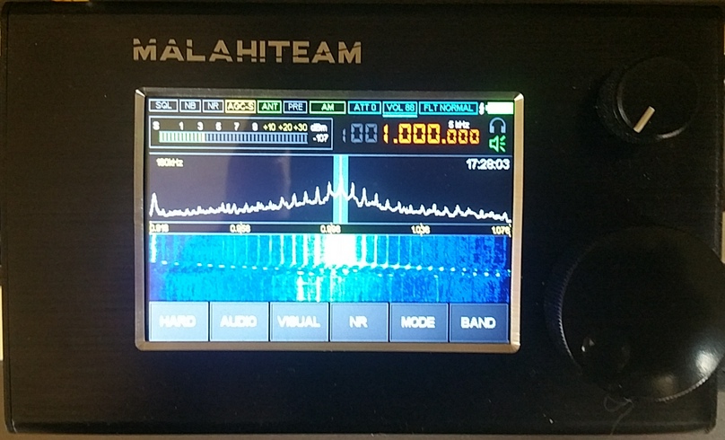
NOISE FROM THE DISPLAY
Example of noise on 1,000 kHz
As I was testing my Malahit DSP-2 it quickly became clear that there is one major low point, and thus a challenge for Georgiy and other members of the design team.
There’s no other way to say this: internally-generated noise remains the major issue keeping the Malahit from achieving greatness.
The developers of the Russian version receiver have not attempted to hide this, and users noticed it from the beginning, with one writer identifying “internally generated noise, which peaks at various frequencies” as one of the key drawbacks of the Malahit.
I had hopes that the DSP-2 version of the Russian-originated Malahit might have less of this problem. There are numerous internally-generated noise/buzzing spikes, some stronger than others, by my estimation at intervals between 125 and 200 kHz throughout the HF bands.
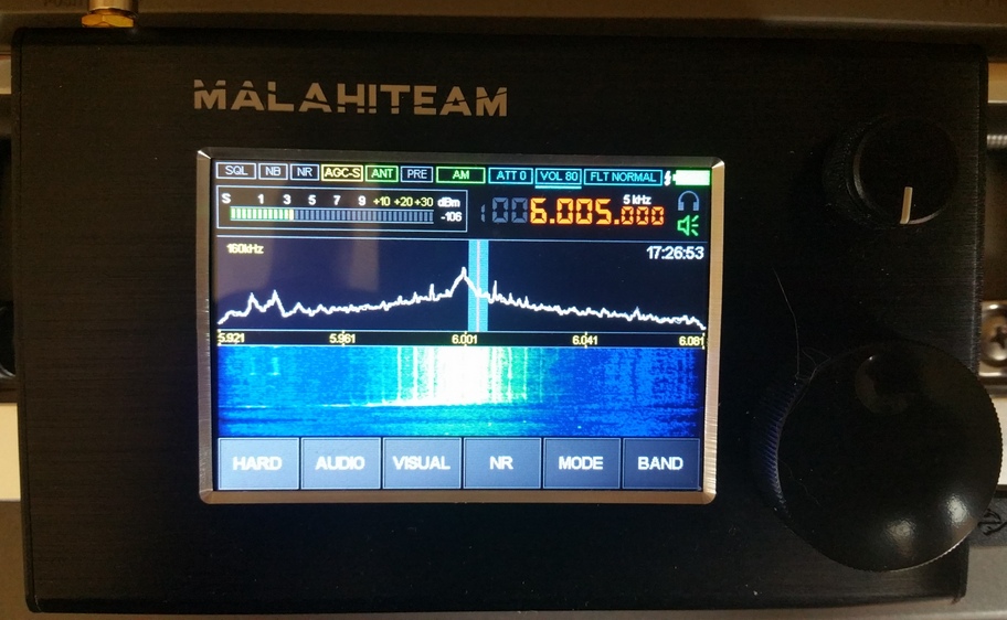
Example of noise on 6,000 kHz (RHC)
In the case of one huge noise spike appearing at or around 6,000 kHz – right over Radio Havana – it ruins any chance of hearing clear signals at, below and above that point. As you can see in my video, the Belka DX does not have this problem (note: apologies for mis-spelling Malahit as Malachit).
Via Telegram, Georgiy asserted to me that when using an external antenna, noise is not as serious, and notes differences between the Malahit and Belka. The Belka, he says, is a simpler device that concentrates only on shortwave, while Malahit is a wide band receiver with more complex DSP and user functions.
“When Belka cannot receive something, Malahit can. And where Belka does not have noise, Malahit has it. These devices are in different classes.”
The result is that a major workaround is often necessary – to disable the VIEW PAN&WTF option, a key feature that is a major highlight of the radio.
Georgiy says that this problem is mainly linked to telescopic antenna antenna operation because of the antenna’s proximity to the display. But as you can see in my video, when testing the Malahit and Belka on 6,000 kHz it’s a night and day situation.
A quick push of the power button blanks out the display completely – and seems to completely resolve the noise issue. But you don’t buy a radio to see a dark display, and it’s depressing to think that turning off a major feature, namely panoramic display, has to be part of standard operating procedure.
When testing the Malahit from its bottom frequency of 50 kHz, even with the PAN & WTF off, huge buzzing noise spikes are heard. In mediumwave/AM, they are seen at 615 kHz, 790 kHz, 965 kHz, 1140 kHz and so on.
If a radio had emerged from a known large manufacturer with this issue, such as Tecsun or Sangean, it would have been roundly condemned by users and reviewers and sent back to the drawing board.
Georgiy does say that in the new firmware interference from the display was decreased, with a “step of about 2.5 MHz, from 1MHz (i.e. 1MHz, 3.5MHz, 6MHz). After correction it will be with a step [of] 4 MHz”. I’m not quite sure what he’s saying with this, due to language issues, but the overall indication is that he is aware of this issue and will continue trying to tackle it in future revisions.
CW DECODING
In the MODE section of the Malahit there is no confirmation that the receiver is actually in CW. Decoding is enabled with an icon, but again no confirming icon at the top of the display. This is a bit odd.
Going to the Telegram app discussion group for the Malahit, and re-reading the translated Russian manual, I discovered that confirmation of CW appears as a white bar under the SPEAKER/HEADPHONE icon on the right. There is also a MINIMUM SNR option in decoding, with a 0 to 70 range.
A You Tube video (the Gerry DX channel) shows the decoding process and notes that it’s important to keep the filter setting at NARROW when attempting to use the decoding feature on the Malahit and also important to set the SNR at the right level.
One would think that this could be easily rectified, but adding a CW indicator to the top row of small icons on the front display might not be as easy as one thinks, unless the display can be modified to also display “CW” in the icon spaces for AM, LSB, or USB.
It turns out that CW decoding on the Malahit works quite well, at least in my attempts. I was able to decode fairly strong CW signals in 40 meters.
LCD/TOUCH SENSITIVITY
When I first got the Malahit, I was puzzled by what seemed to be a serious lack of sensitivity on the display when trying to use the touch icons to change configurations and modes.
This was so bothersome that I raised it with Georgiy who responded that this is by design. The present capacitive touch method, he says, is preferable and more comfortable for users. “If [we were to] change the touch [enable faster response] then [some] people will demand to decrease it.”
With benefit of some time, I have concluded that a slightly firmer and longer press of about half a second to a second almost always brings up the menu selected. But this is definitely a characteristic of the DSP-2, so potential owners should be aware of it.
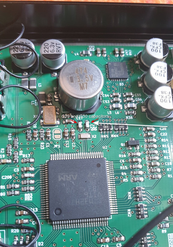
ISSUE WITH CLOCK
Another issue that prospective purchasers should be aware of involves instances where the internal clock of the receiver does not retain the time, and the solution for this directly from Georgiy is not necessarily satisfactory.
“Yes, they need to be removed from the PCB” he says, a reference to two capacitors on the main PCB, C29 and C30 which are next to each other below a larger M7 device on the PCB.
These are SMDs so anyone without good soldering skills will be hard pressed to want to mess around with that PCB. This is not a confidence-builder, nor a solution – clearly these receivers should come from the supplier without such an issue.
This was upsetting enough for some users that the Malahit team faced some sharp criticisms. One user said the clock on his DSP-2 was working perfectly. Another said: “Unless I power off the unit the date stays good but the time is always 2 hrs and 10 minutes behind. As soon as I power off the unit the date defaults back to 15:08:2062.”
One user said: “Problem is voltage is very inaccurate causing the clock settings to be lost. I have tried several 18650 batteries (good Panasonics) and fully charged they are 4.2v, but the DSP-2 indicates 4.6v. When the battery runs down to 4.0v the clock settings are lost. Also, the battery indicator continues to show FULL. I think there is an internal problem with the DSP2. Perhaps the new design, or new internal parts are causing this. This is very disconcerting.”
In exchanges on Telegram, Georgiy said he personally checks each outgoing Malahit for sensitivity on each band, and clock operation, among other things. In a later comment just before this article went to press, Georgiy said that C29/C30 should be replaced only if there is a problem with the clock.
There is no mention by the Malahit team of any official return policy – which of course would be quite challenging and costly involving an additional round trip for a receiver back to Russia and then back again to the user.
On my DSP-2, which I have used with an Anker 26800 USB battery, so far my clock/date settings have maintained accuracy with no reset, even after the USB cable is unplugged from the receiver. I have not yet tested longer times to see if the clock/date is reset when voltage drops below a certain point.
[UPDATE: 22 July 2021]
In a message sent after publication, Georgiy says that the C29 and C30 capacitors will be deleted from the next series of the Malahit, and for now they are being removed from receivers that have not been sold yet.
[UPDATE 23 July 2021]
Further testing revealed that the observations of Malahit users are accurate. When voltage of a 18650B battery in my Malahit dropped below 3.7 v the receiver did indeed shut down — this is with the battery icon still showing 50%. So this is definitely an issue that needs to be addressed in future updates. That said, I got hours of operating time before the full 18650 dropped to the cutoff level — but obviously an inaccurate battery icon is something that the Malahit team will have to correct.
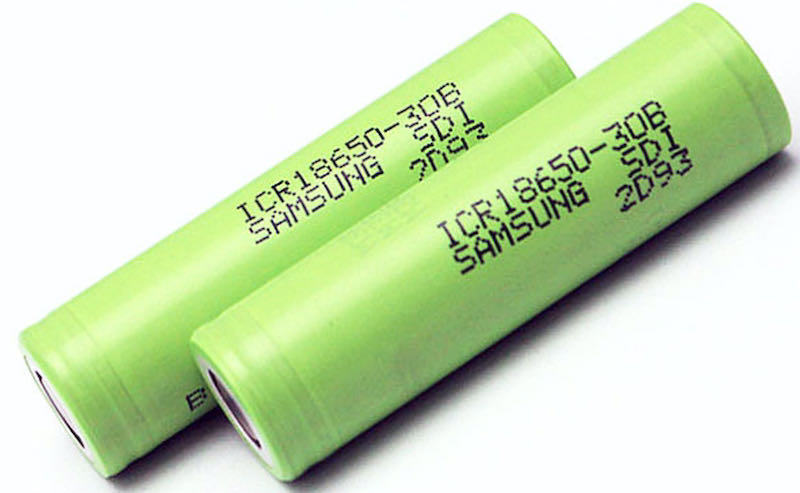
THE BATTERY GAME
Example of 18650 rechargeable batteries
The Malahit DSP-2 uses a 18650 Li-on battery. Unfamiliar to many people, these are actually well known among professional-grade flashlight collectors/users (flashlight collecting is another of my vices).
One of the first things I realized when my Malahit arrived was that my existing button top 18650 cells were too long to comfortably fit in the battery tray. A bit of research on the Facebook Malahit group page revealed that some users have modified the receiver to take two 18650 cells, with a double tray replacing the single tray.
The original Malahit tray requires shorter “unprotected” flat top 18650 cells. At the time I write this, there is a shortage of these cells at the major battery / flashlight suppliers (Battery Junction is one). DO NOT try to force a slightly larger 18650 in the stock Malahit battery tray!
So, one recommendation I would make to the Malahit Team in Russia would be to make it possible for the receiver to use regular protected button top 18650s, of the type one would easily use in a Tecsun receiver such as the 909x and H-501x.
However, in a message to me just before this article went to press, Georgiy said that the Malahit team has used “typical holders” available to them and that they had been unable to obtain a sufficient number of alternative trays for protected 18650 button top batteries. So, for now at least the Malahit will require unprotected flat tops.
My 18650B flat top batteries arrived just as I was completing this review – easily charged up in my Littokala charger, each then fit easily in the single battery tray and power the Malahit perfectly.
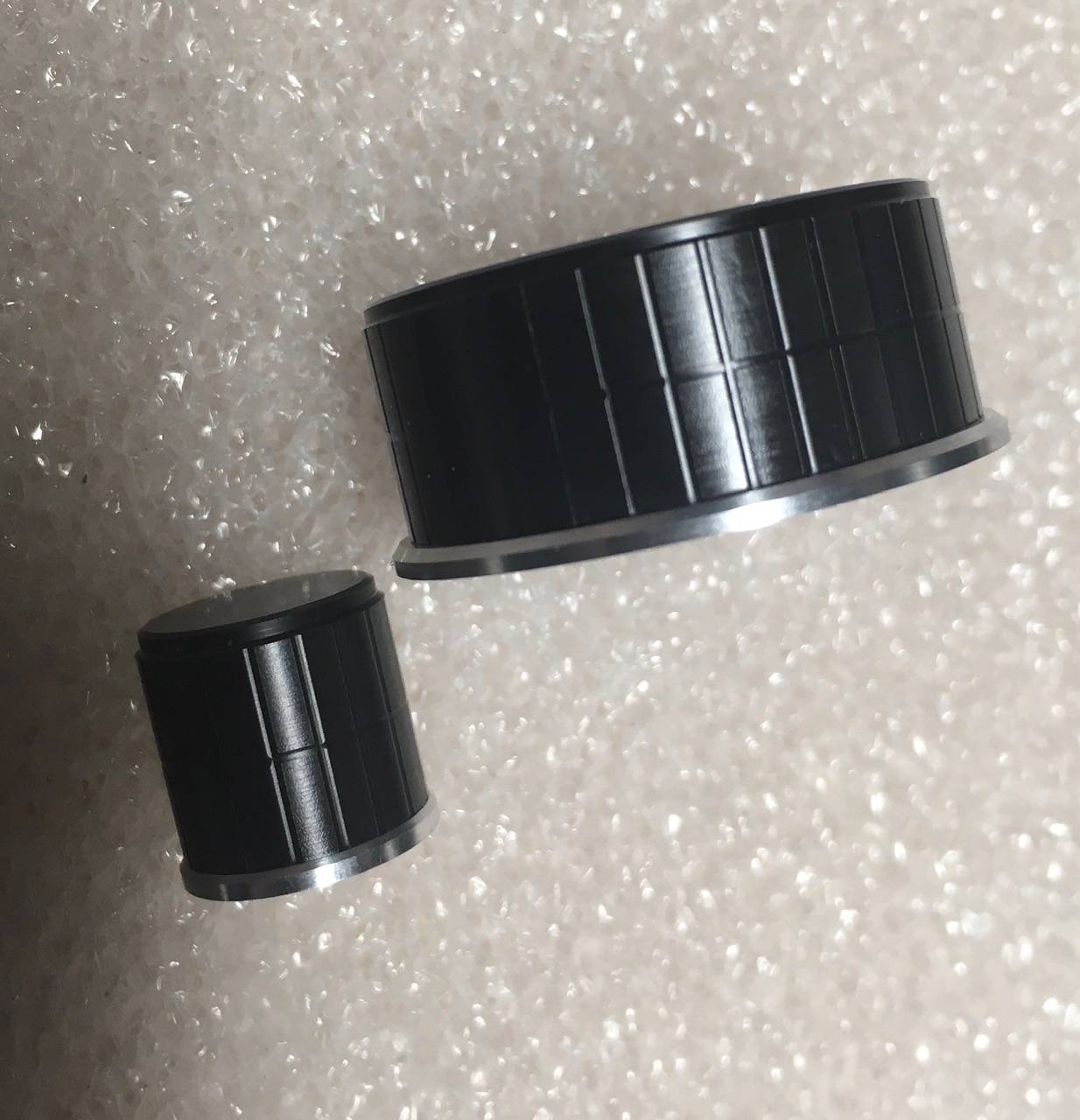
ENCODER KNOBS
Higher quality replacement knobs
The original encoder knobs on the Malahit can be replaced by higher quality, metal construction ones for the small and larger knobs. I got mine from Nikolay, a member in Russia of the Malahit Facebook group (he says he sources them from Switzerland, but I have not confirmed this).
I am, however, not sure that the new knobs can simply be installed on the Malahit – there are no set screws on the original plastic Malahit knobs and I chose not to mess around to see whether the metal knobs can easily be installed, at least for now. Price for the higher quality metal knobs: $17
[UPDATE 23 July 2021]
Nikolay Vedeneev in Russia produces high quality encoder knobs for the Malahit, Afedri, and Belka SDR receivers. He can be reached at: [email protected] and received a very positive review from Fernando Duarte who is known for his reviews of numerous receivers. Both of his knobs fit perfectly on the shafts of my Malahit DSP-2 and have a much better feel than the originals (NOTE: I used a 1.5 mm hex key to tighten the set screws) https://fenuradio.blogspot.com/2020/07/custom-tuning-knopfe-fur-jedes-gerat.html
The subtitle of this article asks whether the Malahit is poised on the edge of greatness. I believe it is, but anyone’s choice to join the Malahit user/fan club comes with some headaches.
We can only hope that the Malahit team can work on the problem of noise spikes that permeate the lower frequency ranges from mediumwave on up. There’s no way to minimize this: at $263 (the price of a DSP-2 as of July 2021) buyers should not have to be shutting off the display to eliminate noise.
As for the question of the clock on the DSP-2 not maintaining time/date, etc it’s clear that Georgiy and the Malahit team are aware of this issue and one hopes this could be checked off the list of concerns that users have raised.
Whether one needs all the bells and whistles that a Malahit offers is the major question, especially when the Belka DX offers excellent stepped (not continuously adjustable) audio filtering and a form of synchronous AM detection in what has to be the smallest high performance receiver ever available to the listener.
More than a few Malahit owners have observed that between 1.5 MHz and 30 MHz the Belka DX seems to be the better shortwave receiver, with no display noise issues, superb battery life and an amazing small size that makes it the ultimate ultra-portable.
In short, if you choose to step aboard the Malahit train you enter a world where there will be constant improvements in software and hardware, and bugs along the way, of which noise spikes issue is a perfect example. But if you’re someone who gets enjoyment from being on the leading edge of technology in radio development, the Malahit may be for you.
It’s impressive that the Malahit originated in Russia, not generally been known for innovations at this level. In recent years, Asia was the main source of advances from the likes of ICOM, Yaesu, AOR etc in the amateur radio area, and from Tecsun, Sangean, and Eton in the area of portable receivers for HF listeners.
Finally, one has to wonder about the potential that the Malahit design holds for integration into the kind of portables seen over the past two years. Some observers have asked why the LCD display and other features on the Malahit could not be part of a future receiver that looks like a Tecsun 990x or Sangean 909×2 with additional advances such as off-air microSD recording, and DRM.
FINAL ASSESSMENT: I boarded the Malahit bus fairly late, but I am definitely a fan. Owning one of these receivers is indeed a roller coaster – anyone climbing on should become a member of the Facebook and other discussion groups where users exchange views, suggestions, and their own experiences.
For ultimate portability in 2021, the Belka DX wins the race. But the Malahit wins on the sheer number of advanced signal processing and other features it contains, though it is hobbled to an extent by the problem of display interference.
If Georgiy and the Malahit team can continue to make steady progress in confronting the noise issue and fine tune the already amazing array of features, the Russia-made Malahit has a bright future ahead.
[UPDATE 24 July 2021]
In the latest firmware update to the Malahit DSP-2, Georgiy provides this
changelog. Note that this is still described as “TEST” firmware, so it’s still unclear
whether he intends to put out a non-TEST version of this particular upgrade:
Firmware 2.10 TEST:
fixed battery voltage indication
fixed behavior of encoder buttons at low supply voltage
protection against false switching has been made – for switching on by three, set switch 2 to the On position.
added test function – increased display frequency. This reduces noise and increases the number of frames per second; To enable this function, set switch 3 to On. The function may not work correctly, if so, please let me know
the level of interference from the display is slightly reduced
changed the distribution of frequencies to which the input high-pass filters are turned on
when HiZ is turned on, the power supply of the external active antenna is automatically turned off;
added indication of external antenna power on – now the ANT indicator is highlighted in red if this function is enabled
the algorithm for displaying the picture on the display, slightly reduces the level of interference
changed the panorama display mode from “Pan & WTF Disabled / Enabled” to “Pan & WTF Single / Always”, while the panorama image is now always present, but it is updated once (when the settings are changed) or always.
fixed attenuators bugs
[UPDATE 2, 24 July 2021 ]
Please read this updated post explaining why I believe you should hold off on making the DSP-2 purchase until software and hardware issues have been resolved.

 Many thanks to SWLing Post contributor, David Day (N1DAY), for sharing the following guest post: