Category Archives: Radios

“Letters of a Radio-Engineer to His Son”

Many thanks to SWLing Post contributor, Paul, who shares a link to Letters of a Radio-Engineer to his Son by John Mills. The book, originally published in 1922, is in the public domain and shared/hosted on the Project Gutenberg website.

It is a fascinating read. Mills does a rather amazing job explaining complex electronic principles in a simple narrative form.

To give you a taste, check out Letter 3 – How a Battery Works below:


LETTER 3
HOW A BATTERY WORKS

(This letter may be omitted on the first reading.)

My Dear Boy:

When I was a boy we used to make our own batteries for our experiments. That was before storage batteries became as widely used as they are to-day when everybody has one in the starting system of his automobile. That was also before the day of the small dry battery such as we use in pocket flash lights. The batteries which we made were like those which they used on telegraph systems, and were sometimes called “gravity” batteries. Of course, we tried several kinds and I believe I got quite a little acid around the house at one time or another. I’ll tell you about only one kind but I shall use the words “electron,” “proton,” “nucleus,” “atom,” and “molecule,” about some of which nothing was known when I was a boy.

We used a straight-sided glass jar which would hold about a gallon. On the bottom we set a star shaped arrangement made of sheets of copper with a long wire soldered to it so as to reach up out of the jar. Then we poured in a solution of copper sulphate until the jar was about half full. This solution was made by dissolving in water crystals of “blue vitriol” which we bought at the drug store.

17Blue vitriol, or copper sulphate as the chemists would call it, is a substance which forms glassy blue crystals. Its molecules are formed of copper atoms, sulphur atoms, and oxygen atoms. In each molecule of it there is one atom of copper, one of sulphur and four of oxygen.

When it dissolves in water the molecules of the blue vitriol go wandering out into the spaces between the water molecules. But that isn’t all that happens or the most important thing for one who is interested in making a battery.

Each molecule is formed by six atoms, that is by six little groups of electrons playing about six little nuclei. About each nucleus there is going on a game but some of the electrons are playing in the game about their own nucleus and at the same time taking some part in the game which is going on around one of the other nuclei. That’s why the groups or atoms stay together as a molecule. When the molecules wander out into the spaces between the water molecules something happens to this complicated game.

It will be easiest to see what sort of thing happens if we talk about a molecule of ordinary table salt, for that has only two atoms in it. One atom is sodium and one is chlorine. The sodium molecule has eleven electrons playing around its nucleus. Fairly close to the nucleus there are two electrons. Then farther away there are eight more and these are having a perfect game. Then still farther away from the nucleus there is a single lonely electron.

The atom of chlorine has seventeen electrons which 18play about its nucleus. Close to the nucleus there are two. A little farther away there are eight just as there are in the sodium atom. Then still farther away there are seven.

I am going to draw a picture (Fig. 1) to show what I mean, but you must remember that these electrons are not all in the same plane as if they lay on a sheet of paper, but are scattered all around just as they would be if they were specks on a ball.

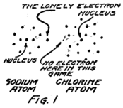
You see that the sodium atom has one lonely electron which hasn’t any play fellows and that the chlorine atom has seven in its outside circle. It appears that eight would make a much better game. Suppose that extra electron in the sodium atom goes over and plays with those in the chlorine atom so as to make eight in the outside group as I have shown Fig. 2. That will be all right as long as it doesn’t get out of sight of its own nucleus because you remember that the sodium nucleus is responsible for eleven electrons. The lonely electron of the sodium atom needn’t be lonely any more if it can persuade its nucleus to stay so close to the chlorine atom that it can play in the outer circle of the chlorine atom.

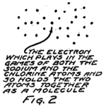
The outer circle of the chlorine atom will then have a better game, for it will have just the eight that makes a perfect game. This can happen if the chlorine atom will stay close enough to the sodium atom so that the outermost electron of the sodium atom can play in the chlorine circle. You see everything will be satisfactory if an electron can be shared by the two atoms. That can happen only if the two atoms stay together; that is, if they form a molecule. That’s why there are molecules and that’s what I meant when I spoke of the molecule as a big game played by the electrons of two or more atoms.

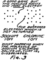
This molecule which is formed by a sodium atom and a chlorine atom is called a molecule of sodium chloride by chemists and a molecule of salt by most every one who eats it. Something strange happens when it dissolves. It wanders around between the water molecules and for some reason or other–we don’t know exactly why–it decides to split up again into sodium and chlorine but it can’t quite do it. The electron which joined the game about the chlorine nucleus won’t leave it. The result is that the nucleus of the sodium atom gets away but it leaves this one electron behind.

What gets away isn’t a sodium atom for it has one too few electrons; and what remains behind isn’t a chlorine atom for it has one too many electrons. We call these new groups “ions” from a Greek word which means “to go” for they do go, wandering off into the spaces between the water 20molecules. Fig. 3 gives you an idea of what happens.

You remember that in an atom there are always just as many protons as electrons. In this sodium ion which is formed when the nucleus of the sodium atom breaks away but leaves behind one planetary electron, there is then one more proton than there are electrons. Because it has an extra proton, which hasn’t any electron to associate with, we call it a plus ion or a “positive ion.” Similarly we call the chlorine ion, which has one less proton than it has electrons, a minus or “negative ion.”

Now, despite the fact that these ions broke away from each other they aren’t really satisfied. Any time that the sodium ion can find an electron to take the place of the one it lost it will welcome it. That is, the sodium ion will want to go toward places where there are extra electrons. In the same way the chlorine ion will go toward places where electrons are wanted as if it could satisfy its guilty conscience by giving up the electron which it stole from the sodium atom, or at least by giving away some other electron, for they are all alike anyway.

Sometimes a positive sodium ion and a negative chlorine ion meet in their wanderings in the solution and both get satisfied by forming a molecule 21again. Even so they don’t stay together long before they split apart and start wandering again. That’s what goes on over and over again, millions of times, when you dissolve a little salt in a glass of water.

Now we can see what happens when copper sulphate dissolves. The copper atom has twenty-nine electrons about its nucleus and all except two of these are nicely grouped for playing their games about the nucleus. Two of the electrons are rather out of the game, and are unsatisfied. They play with the electrons of the part of the molecule which is called “sulphate,” that is, the part formed by the sulphur atom and the four oxygen atoms. These five atoms of the sulphate part stay together very well and so we treat them as a group.

The sulphate group and the copper atom stay together as long as they are not in solution but when they are, they act very much like the sodium and chlorine which I just described. The molecule splits up into two ions, one positive and one negative. The positive ion is the copper part except that two of the electrons which really belong to a copper atom got left behind because the sulphate part wouldn’t give them up. The rest of the molecule is the negative ion.

The copper ion is a copper atom which has lost two electrons. The sulphate ion is a combination of one sulphur atom, four oxygen atoms and two electrons which it stole from the copper atom. Just as the sodium ion is unsatisfied because in it there is one more proton than there are electrons, so the copper ion is unsatisfied. As a matter of fact it is twice 22as badly unsatisfied. It has two more protons than it has electrons. We say it has twice the “electrical charge” of the sodium ion.

Just like a sodium ion the copper ion will tend to go toward any place where there are extra electrons which it can get to satisfy its own needs. In much the same way the sulphate ion will go toward places where it can give up its two extra electrons. Sometimes, of course, as ions of these two kinds wander about between the water molecules, they meet and satisfy each other by forming a molecule of copper sulphate. But if they do they will split apart later on; that is, they will “dissociate” as we should say.

Now let’s go on with the kind of batteries I used to make as a boy. You can see that in the solution of copper sulphate at the bottom of the jar there was always present a lot of positive copper ions and of negative sulphate ions.

On top of this solution of copper sulphate I poured very carefully a weak solution of sulphuric acid. As I told you, an acid always has hydrogen in its molecules. Sulphuric acid has molecules formed by two hydrogen atoms and one of the groups which we decided to call sulphate. A better name for this acid would be hydrogen sulphate for that would imply that its molecule is the same as one of copper sulphate, except that the place of the copper is taken by two atoms of hydrogen. It takes two atoms of hydrogen because the copper atom has two lonely electrons while a hydrogen atom only has one. It takes two electrons to fill up the game which the 23electrons of the sulphate group are playing. If it can get these from a single atom, all right; but if it has to get one from each of two atoms, it will do it that way.

I remember when I mixed the sulphuric acid with water that I learned to pour the acid into the water and not the other way around. Spatterings of sulphuric acid are not good for hands or clothes. With this solution I filled the jar almost to the top and then hung over the edge a sort of a crow’s foot shape of cast zinc. The zinc reached down into the sulphuric acid solution. There was a binding post on it to which a wire could be connected. This wire and the one which came from the plate of copper at the bottom were the two terminals of the battery. We called the wire from the copper “positive” and the one from the zinc “negative.”

Now we shall see why and how the battery worked. The molecules of sulphuric acid dissociate in solution just as do those of copper sulphate. When sulphuric acid molecules split, the sulphate part goes away with two electrons which don’t belong to it and each of the hydrogen atoms goes away by itself but without its electron. We call each a “hydrogen ion” but you can see that each is a single proton.

In the two solutions are pieces of zinc and copper. Zinc is like all the rest of the metals in one way. Atoms of metals always have lonely electrons for which there doesn’t seem to be room in the game which is going on around their nuclei. Copper as we saw has two lonely electrons in each atom. Zinc 24also has two. Some metals have one and some two and some even more lonely electrons in each atom.

What happens then is this. The sulphate ions wandering around in the weak solution of sulphuric acid come along beside the zinc plate and beckon to its atoms. The sulphate ions had a great deal rather play the game called “zinc sulphate” than the game called “hydrogen sulphate.” So the zinc atoms leave their places to join with the sulphate ions. But wait a minute! The sulphate ions have two extra electrons which they kept from the hydrogen atoms. They don’t need the two lonely electrons which each zinc atom could bring and so the zinc atom leaves behind it these unnecessary electrons.

Every time a zinc atom leaves the plate it fails to take all its electrons with it. What leaves the zinc plate, therefore, to go into solution is really not a zinc atom but is a zinc ion; that is, it is the nucleus of a zinc atom and all except two of the planetary electrons.

Every time a zinc ion leaves the plate there are left behind two electrons. The plate doesn’t want them for all the rest of its atoms have just the same number of protons as of electrons. Where are they to go? We shall see in a minute.

Sometimes the zinc ions which have got into solution meet with sulphate ions and form zinc sulphate molecules. But if they do these molecules split up sooner or later into ions again. In the upper part of the liquid in the jar, therefore, there are sulphate 25ions which are negative and two kinds of positive ions, namely, the hydrogen ions and the zinc ions.

Before the zinc ions began to crowd in there were just enough hydrogen ions to go with the sulphate ions. As it is, the entrance of the zinc ions has increased the number of positive ions and now there are too many. Some of the positive ions, therefore, and particularly the hydrogen ions, because the sulphate prefers to associate with the zinc ions, can’t find enough playfellows and so go down in the jar.

Down in the bottom of the jar the hydrogen ions find more sulphate ions to play with, but that leaves the copper ions which used to play with these sulphate ions without any playmates. So the copper ions go still further down and join with the copper atoms of the copper plate. They haven’t much right to do so, for you remember that they haven’t their proper number of electrons. Each copper ion lacks two electrons of being a copper atom. Nevertheless they join the copper plate. The result is a plate of copper which has too few electrons. It needs two electrons for every copper ion which joins it.

How about the zinc plate? You remember that it has two electrons more than it needs for every zinc ion which has left it. If only the extra electrons on the negative zinc plate could get around to the positive copper plate. They can if we connect a wire from one plate to the other. Then the electrons from the zinc stream into the spaces between the atoms of the wire and push ahead of them the electrons 26which are wandering around in these spaces. At the other end an equal number of electrons leave the wire to satisfy the positive copper plate. So we have a stream of electrons in the wire, that is, a current of electricity and our battery is working.

That’s the sort of a battery I used to play with. If you understand it you can get the general idea of all batteries. Let me express it in general terms.

At the negative plate of a battery ions go into solution and electrons are left behind. At the other end of the battery positive ions are crowded out of solution and join the plate where they cause a scarcity of electrons; that is, make the plate positive. If a wire is connected between the two plates, electrons will stream through it from the negative plate to the positive; and this stream is a current of electricity.

Pl. III.–Dry Battery for Use in Audion Circuits (Courtesy of National Carbon Co., Inc.) Storage Battery (Courtesy of the Electric Storage Battery Co.).


Click here to read the entire book.

Just pulled the trigger on the new QCX+ CW/WSPR QRP transceiver kit

I’m a real sucker for kits of any stripe.

A few days ago, my buddy, Pete (WB9FLW), sent me a tip about the new QCX+ CW/WSPR transceiver by QRP Labs. I posted an announcement on QRPer.com.

I’ve yet to build a QRP Labs kit, but I’ve only heard positive reviews from readers and friends. QRP Labs’ president, Hans Summers (G0UPL), is an amazing kit designer and, indeed, won the 2019 Homebrew Heroes Award.

Hans kindly took a break so that I could snap his photo at Hamvention 2019.

Last year, at the 2019 Hamvention, QRP Labs had a table across from ours and, based on the amount of people huddled around his table all day long, I’m certain he was one of the busiest vendors at Hamvention.

His new QCX+ transceiver is an upgraded/updated version of the original QCX transceiver which has sold nearly 10,000 units. In the following video, Hans describes in detail how the QCX+ is designed and the differences between it and its predecessor:

Since I’ve quite a few things on my Social DX bucket list–including the recent addition of QRP EME (I mean, what am I thinking?)–and since I don’t really need yet another CW QRP transceiver, I required a good excuse to buy and build this kit. So I turned to my editor at RadCom who very much wanted review. Fantastic excuse! Thank you!

The amazing thing about the QCX+ is you getting a full-featured single band QRP transceiver for $55 US plus a modest shipping fee. This means pretty much anyone can afford to buy and build one.

I just placed an order for the transceiver ($55) with a 40M band module, the optional custom aluminum enclosure ($25), and the optional GPS receiver ($23). If I had a 3D printer, I might have skipped the enclosure because I’m willing to bet that shortly after the transceiver’s release, someone will share an enclosure design one can print at home. Then again, since I know I’ll take this little rig to the field, an aluminum enclose will provide excellent protection.

I purchased the optional GPS receiver because I plan to eventually put this rig into use as a dedicated WSPR beacon. The GPS module will calibrate the frequency, time, and Maidenhead Locator grid square in WSPR mode. It can also be used to precisely calibrate the transceiver’s synthesizer reference oscillator.

Kit anticipation time!

According to the QRP Labs website, they plan to start shipping the QCX+ in mid-June. I opted for FedEx delivery, so hopefully it’ll arrive sometime around my birthday (Happy Birthday to me!).

More than anything, I simply enjoy building kits and really look forward to building the QCX+, then putting it on the air! I’ll post updates and a few photos here, but look for my full review likely this fall in the pages of RadCom.

Post readers: Please comment if you’ve built a QRP Labs kit or have any other kits in the pipeline this summer!

Listener Post: Fabien’s love of radio which lead him to collecting

Fabien’s radio story below is the latest in our series called Listener Posts, where I place all of your personal radio histories.

If you would like to add your story to the mix, simply send your story by email!

In the meantime, many thanks to Fabien who writes:


I’ve been a radio listener since the age of 14. I was an SWL and a listener of local VHF free stations too.

In the beginning, my receiver was a poor radio-cassette, with a little segment of the shortwave bands. I used it for two years.

Then, for 16th birthday I received a Philips AL 990 shortwave receiver.

It was a great receiver because the sound was clear and it was easy to identify the stations when listening with my usual headphones–even those broadcasts with very weak signals and an unidentified language. The negative of this receiver was the frequency was not easy to see/read and I was at the same display for hours.

After my school period, I worked for two years and with my savings I was able to buy a JRC NRD 525 in Swizterland, where this receiver was less expensive and easier to find than in my country of France at the time.

The Japan Radio Company NRD 525 receiver. Photo: Universal Radio

The good with the NRD 525 is that it was easy to tune to a frequency, easy to read the display and easy to connect the receiver to another unit for decoding RTTY signals with an old computer monitor and a small EPSON dot printer.

I was in paradise!

But the NRD 525 has a problem with its sound. Even with my best headphones, I was not able to understand the station voices when the signal was poor and the language was not mine, so it was difficult to have sufficient details to make a good reception report for sending it proudly to the logged radio station.

My solution was strange but the only one possible : I searched for rare signals with the NRD 525 and after I found them, listened to those signals with the AL 990 and my headphones.
With this solution, I was able to send a lot a reception reports and receive some beautiful QSLs from official, pirate and clandestine stations (clandestines were my favorites).

This SWL period was until 1988. In 1988 I was obliged to move from my city to a new location where it was more difficult to be a SWL. The following years, I was more a BCL (Broadcast Listener) than an SWL.

I did BCL DX until 1999, and after 1999 most of my radio listening time was only BCL easy listening, without looking for weak signals.

Because of the Internet, online SDRs, and the closing down of a lot of broadcasters, I’m less  interested in contact stations directly, save from time to time. For me, the chase of weak signals was the most important part; now we can listen to a station via the Internet (online on a website or with a SDR online)…even the pirates stations.

My actual interest today is to have all of the receivers I was dreamed about when I was a teenager. In 2020, at 53 years old, I am now more a collector of receivers than a real BCL. I like all electronics, including many hifi systems/components and radio items.

I also love black and white film photography/laboratory too and I collect stickers from French radio stations.

Here are two pictures of part of my actual listening post. On one, you could see a model boat of the famous offshore radio station ” Radio Caroline “.

My favorite shortwave receivers are the Drake R8-E (European version of the R8), the BEARCAT DX-1000 and the Yaesu FRG-7.

My favorite receiver for synchronous detection reception is the SONY ICF-2001D (the European version of the ICF 2010).

To receive mediumwave stations, I prefer my JRC NRD 515 connected with an Australian active loop antenna.

For travel, I use a small Lowe HF 150.

For VHF FM-commercial band, I use my Grundig Satellit 500 and a Sony ICF 6800W.

Some of my best souvenirs/memories of SW reception are Radio La Voz de Alpha 66 (USA), Radio Venceremos (El Salvador), Radio Botswana, Radio Bardaï (Tchad or Libia), Radio RFO Tahiti, and Radio Bandeirantes (Brasil).

My regrets from the years 1981-1988 are not being able to receive the signal of Radio BHUTAN and the signal from The Faklands Islands.

I don’t like to travel outside my beloved country, but for the pleasure of visiting some radio stations, I made an effort and I traveled to Phnom Penh (Cambodia), La Habana (Cuba), San Salvador (El Salvador) and Ciudad Guatemala (Guatemala).

Truly Yours,
Fabien SERVE, in France


Thank you, Fabien, for sharing your story! You’ve added some truly classic receivers to your collection over the years!  I love the Radio Caroline model too! 

I encourage other SWLing Post readers and contributors to submit their own listener post! Tell us how you became interested in radio! 

Build an SDR station and balcony antenna farm for less than 150 Euros

UPDATE 11 May 2020: We recently learned that the MSI.SDR software defined radio dongle in the following post and tutorial is a clone of the SDRplay RSP1 SDR. We did not realize this when the post was published. Grayhat had done research prior to purchase and believed it not to be a clone, but only using the same chipset as the RSP1 (hence the compatibility with SDRuno). We have confirmed that it is indeed a clone now via SDRplay (clear here to read more via the excellent RTL-SDR blog). What follows isn’t an SDR review. Indeed, Grahat’s post has little to do with the receiver and much, much more to do with building proper antennas! We’ve removed links to the MSI.SDR and would encourage you to invest in the excellent SDRplay RSP1a instead (click here to read our RSP1a review). Thank you for understanding!

Many thanks to SWLing Post contributor, Grayhat, who shares the following guest post. He lives in Italy and has been in lock-down since the beginning of the pandemic. He pitched the idea of building an entire SDR setup from scratch–receiver and antennas–for less than 150 Euros (roughly $163 USD). I thought it was a brilliant idea and I believe he thoroughly enjoyed the challenge of sourcing the components and building a mini antenna farm on his balcony while in quarantine:


From Zero to SDR

by Grayhat

What follows doesn’t pretend to be some kind of “definitive guide” or “last word”, on the contrary, it’s aimed at people who have little or no experience with SDR but want to try putting together a decent station without paying an arm and a leg.

The idea of writing this came to me after reading a number of messages and discussions on various online groups/forums, in a lot of cases, someone bought an SDR (usually the ones coming with a telescopic whip antenna), and after connecting it was expecting it “just to work” or, better said, pretending that the SDR connected to that whip (usually placed on a table right near the computer) could receive ANY POSSIBLE signal, including transmissions coming from the “dark side of the moon.” 🙂 Those folks got scared by the fact that the SDR “didn’t work” and decided to give up; now, this short “guide”  should allow anyone to setup what’s needed to have a working SDR

My self-imposed limitations for this project/experiment were the following:

  1. The whole setup shouldn’t cost more than 150 Euros so that, if after trying the SDR one doesn’t like it, (s)he won’t have paid $$$, otherwise, if (s)he decides to keep it, the resulting station will allow for further expansion/improvement
  2. The available space was considered to be that of an apartment, that is, no large field to put up huge wire antennas or to raise towers, the limit was the one of a balcony (in my home) that is 8 meters (max antenna length) by 3 meters (available height) by 2 meters (balcony width)
  3. The whole setup should be simple and straightforward, no need to solder components or to build special types of antennas
  4. Given the current Covid-19 sheltering, most components should be available online, while for others one may arrange with whatever is locally available (e.g. duct tape)

With the above limitations in mind, I took pencil, paper and rubber eraser (high-tech instruments, indeed) and started writing down a list of the needed stuff, after some writing, wiping and second thought, I came out with the following list, available on Amazon:

Bill of materials

The above includes all the needed stuff to put together a number of wire antennas (random wire, random dipole, loop…) the coax to connect the SDR, a balun to match the coax to the antenna and the accessory parts needed to put up the antenna. The selected SDR isn’t the common “RTL SDR” type, not that they don’t work, but their 8 bit ADC is far from being a good performer, so I decided to pick a different SDR which offers a 12 bits ADC and which also “presents itself” to the system as an SDRplay RSP1.

[Please note: we’ve since learned from SDRplay that the MSI.SDR is indeed a clone of the SDRplay RSP1. Here’s a post from the RTL-SDR blog confirming this. We recommend purchasing the RSP1a as a better alternative.]

Anyhow; all I can say is that after some tests, the MSI.SDR is a quite good unit and offers quite a lot of bangs for the buck, so I believe it may be a good unit for people willing to get their feet wet with SDRs

The above being said, here’s a pic of the MSI.SDR unit with the included stuff:

The unit is very small and the box has two connectors, an SMA for the antenna and a micro-USB (like the ones used in cellphones) for the USB cable which is used to both power and control it; the other bits are the telescopic whip antenna (around 98cm fully extended) with a magnetic base and a short run of coax, and the USB cable.

Once I got the SDR I decided to give the included whip antenna a try… well, to be clear, while it will allow you to pick up some strong local FM stations and maybe a bit else, it will only be useful to test if the SDR unit is working (before putting together our antenna), so don’t expect to receive much with that whip, yet… don’t throw it away, it may become useful (more later).

The other important piece is the BalUn. I picked a NooElec “Nine to One” v2, since I’ve used their v1 model and I’ve found it to work well, I decided to pick the newest model which has a better antenna wire connector.  The BalUn, which is in effect a so-called “transformer balun” is really small and the junction box I bought is much bigger, but it isn’t a problem. All in all, the box may host a preamplifier in the future, but for the moment it’s fine for the balun. The following pic shows the balun “installed” inside the junction box:

The scissors are there to give you an idea of the sizes; to put together the whole thing, I started by preparing two pieces of wire (the 2.5mm one),  made a turn with each wire and locked them with a nylon cable tier. Those turns will prevent the wire from sliding out and putting a strain on the balun connector.  I did that since I didn’t have plastic washers at hand, otherwise you may just slide two plastic washers (or proper diameter) over the wires and use two nylon tiers to lock them. In either case, the idea is that the “loops” or the washers won’t slide through the box holes and will support that (little bit of) strain caused by the wire connection.

Next, I stripped some of the insulation from the ends and connected the wires to one of the balun connectors (I chose the one in the pic since I believe it’s the most suitable for this setup), at that point I continued cutting the smaller “ring” of the box insulation caps (the two at top and the bottom one). Then I placed a piece of carboard roll (from a kitchen-paper roll) at the bottom to serve as a support (you can see it below the balun). At that point, I slid the balun SMA connector through the bottom hole and used the SMA to BNC adapter to hold it, done so I slid the two wires (connected to the green wire connector) through the side hole and then inserted the connector into the balun. I then placed the other piece of paper roll above the balun and closed the box with its cap. As a note, to properly close it, start by inserting the screw into the cap holes till end, so that they’ll extrude from the bottom, then place the cap over the box and tighten the screws–you may need to use some force to properly tighten it.

Notice that the wire shown in the pic are SHORT, later on I replaced them with longer wires (outside the box) to be able to better connect the balun box to the antenna, but the remainder of the build is the same.

Now that I had my “balun box” ready, I measured the antenna wire and, using the paracord and some nylon tiers, I installed it. I also installed the “counterpoise” wire. For the latter, at first I tried just connecting the remainder of wire to the “gnd” of the balun, leaving the spool laying on the floor, but later on I decided to hang up the counterpoise and the final result was the following:

Click to enlarge

Not a work of art, but then since I was experimenting, I decided not to add PTFE and tape to allow me to quickly rearrange the antenna to run other configurations, yet, the whole setup worked quite well and stood fine to some wind and rain, the picture below shows the balun box with the antenna/counterpoise wires and the coax with the snap-on ferrite chokes.

Click to enlarge

Notice that to avoid putting strain on the balun wires, I used a wire clamp I had in my junkbox–the clamp is then tied to the paracord using a nylon tier and the paracord holds the assembly and keeps the antenna wire in position. The ferrite chokes aren’t properly seated, and I’m planning to remove and re-place them, but for the moment they’re okay. The balcony faces to south/south-west so the antenna has a free horizon of about 270 degrees ranging from the Adriatic coast to the Appennines (Mt. S.Vicino can be seen behind the paracord)–not bad. Here’s another pic showing the horizon to West, just to give you an idea:

Getting back to the antenna installation, the other end of the antenna wire is tied to the opposite side of the balcony as shown below (let aside the tent/awning, I raise them when using the SDR, also, the bowline knot isn’t correct, I’ll need to tie that again):

The counterpoise instead is supported by a lamp I’ve on the terrace, here’s it’s setup:

The “paracord” goes down to a plastic bottle filled with a water/chlorine mixture which serves to keep it in place. The remainder of the wire is just hanging down for about 1.5 meters (the counterpoise is shorter than the antenna wire, it’s about 2/3 of its length).

Ok, time to put the antenna and SDR to test, so I brought the coax inside home, connected the other SMA to BNC adapter to the SDR and connected the coax going to the antenna. Note that 15 meters of coax is enough for me, but if one wants a length of up to 25 mt, it won’t be a problem.

I already installed the SDR software, in my case since the unit identifies itself as an “SDR1” I downloaded the SDRPlay “SDRuno” software https://sdrplay.com/windl2.php and since I was at it I also downloaded the PDF manual https://www.sdrplay.com/downloads/ and the “CookBook” http://www.nn4f.com/SDRuno-cookbook.pdf and I heartly recommend reading and digesting them before starting the whole thing (while you wait for all the stuff to be delivered). An important note is that you MUST install the SDRuno software BEFORE connecting the SDR since that way, the SDRuno setup will install the proper drivers and you won’t have issues.

Anyhow, I connected the coax to the SDR and then it was time to fire up the whole thing and give it a spin; so I powered up the laptop (technically, a “transformable” laptop/tablet), started SDRuno, opened the “RX control” and “Main Spectrum” windows and then clicked the “play” button, clicked the “broadcast” band, and the “MW” one and got this:

Not exceptional maybe, but not bad, either; in particular if one considers that it’s from a quite short piece of wire which isn’t exactly placed in an ideal position.

Deutsche Welle

So I went on and explored the bands a bit. On ham bands the SDR picked up signals from the whole mediterranean basin (Cyprus, Lebanon, Spain and then some) and from north too (Russia, Germany, Denmark); then depending on time, I was able to clearly receive broadcasts from China, South America, Africa and more ham QSOs from a lot of places.

BBC Ascension Island 5/9+ and just a bit of QSB

I must admit I didn’ record the callsigns or stations identifiers (“guilty” your honor–!) but I was more focused on testing the SDR and antenna than running a “DX session” at any rate.  On the BCB bands I picked up WWV, BBC,  VoA, China Radio International, Radio Free Asia, Radio Romania and a bunch of others from Middle East, Asia, Africa and South America. While on the ham bands, I was able to pick up some quite interesting QSOs and then… well, I went hunting for higher frequencies signals!

I got Police, Ambulances, Air control…so even if that “piece of wire” isn’t optimized for VHF/UHF it seems to be working decently there too. By the way, when changing bands you may (and probably will) need to adjust the gain control, but that will be almost the only thing needed to pull in signals

At the end of the day, I can say that I’m quite pleased with the performance offered by this simple and cheap setup. For less than 150 euros you have everything you need, not just the SDR.

Sure, the setup may be improved, but then again you’ll have all of the basic parts, so you won’t need too much. For example, if you live in a really noisy environment, it would be a good idea to use a loop antenna. You would only need a “cross shaped” support (PVC pipes or wood will do). You could quickly put together the SRL (Small Receiving Loop) designed by Matt Roberts (KK5JY) http://www.kk5jy.net/rx-loop/ the balun will be the SAME (yes, no need to wind whatsoever!) so building it will just be a matter of assembling a cross shaped support for the wire (which we already have because it’s the same used for the wire antenna) and you’ll have it. While I already tried the SRL, I didn’t build one to test with this SDR, but I’ll probably do that as soon as SWMBO will start complaining about those “wires on the balcony.”

Also, at the beginning I wrote “more later” when writing about the telescopic whip included with the SDR. Here’s the idea–it requires soldering, so if you don’t want that, skip this: remove the adhesive sheet on the bottom of the antenna base to expose the bottom cap and then remove (extract) the bottom cap. You’ll see a magnetic ring and a “bell shaped” piece of metal (the “ground” for the whip). In the middle of the “bell” there will be the antenna connector which is soldered to the coax wire with a nut holding the connector (and the “bell”) in place. De-solder the coax, unscrew the antenna connector and extract it, at that point you’ll have the telescopic whip and its connector, now you may use them to build the active “whip” antenna described here:

http://www.techlib.com/electronics/antennas.html#Improved%20Active%20Antenna

Notice that it is NOT the “usual” active whip–the circuitry and idea behind it is totally different–yet it works fine and will serve you from VLF (not kidding) up to around 100MHz. It might be a good companion for the SDR. It won’t be as quiet as the loop, yet it may be a valid “all rounder.”

To conclude, I believe that the setup described above is something anyone can afford. You don’t need to be an engineer or to have special knowledge or abilities–it’s just a matter of putting together some bits and pieces.

Obviously, this setup doesn’t require a large space and offers good performance across the bands. Plus it’s so easy to improve since the 12bit SDR is a good starting point

All the best everyone and STAY HOME, STAY SAFE !


Thank you so much, Grayhat!

I love the fact that you invested (however modestly) in a proper antenna setup to better serve you rather than relying on the basic whip antenna that comes with the SDR. You’re right: too often, we invest a receiver, yet invest no money or time into building an appropriate antenna.  The antenna is the most important component in a proper radio setup and those included telescoping whip antennas simply don’t perform well on the HF bands.

Based on our correspondence, I know you had fun piecing together this little system using a simple bill of materials and items you had on hand during the Covid-19 quarantine. Thank you for sharing it here with your SWLing Post community! 

The Tecsun PL-330: Some details about this compact shortwave portable in development

Source: tecsun.com.cn

Many thanks to a number of SWLing Post readers who shared a link to this website (in Chinese) with photos and details of the new Tecsun PL-330. Note: The server hosting the PL-330 page has been unreliable the past few days.

Some of you might recall the PL-330 in photos of the new Tecsun product line we posted last year. Recently, a handful of preliminary working prototypes have been produced,  so I reached out to my trusted Tecsun contact for more information. Here’s what I’ve learned:

Position in Tecsun product line

In terms of the Tecsun product line, the PL-330 appears to be the successor to the venerable Tecsun PL-310ET and/or PL-380.

The PL-330 will have features these legacy Tecsun models do not have, namely:

  • synchronous detection,
  • single-sideband reception,
  • and an upgraded ETM (auto tune and store) feature.

It also appears the SSB tuning steps could be as fine as 10 Hz. Most impressive, if true.

Size

Size comparison: PL-330 (left), PL-990 (middle), H-501 (right)

I refer to radios in this size class as “ultra-compact.”

The PL-330 measures 139 × 85 × 26 millimeters (5.5 x 3.3 x 1 inches). Its form factor is very similar to the PL-310ET, but much thinner in profile. The total depth of the radio is only 26 mm.

I love the idea of an even thinner profile, although this certainly limits the type of internal battery that can be used.

Battery

The PL-330 is powered by a single BL-5C lithium battery.

In my world, this is a bit of a negative, but I’m sure the BL-5C was one of the only viable battery options for a radio that’s only 26mm thick.

On the plus side, the BL-5C is widely available, affordable, and can be charged internally.

On the negative side?

Well, I find that the overall capacity doesn’t match that of, say, three AA batteries. Also, I find that the battery’s longevity (meaning, how many charge cycles it can handle) is not that impressive–arguably worse than any other rechargeable battery system I’ve used.

Another reason I prefer AA batteries in compact portables is I know no matter where I travel, I can easily purchase them at almost any retailer, airport, or even hotel, in a pinch. In the past, when I’ve traveled with radios that use the BL-5C, I simply carried a fully-charged spare in a poly zip-lock bag (to protect the battery contacts from inadvertently shorting.

In addition, when I fly, I like to carry as few Lithium batteries as possible.

Perhaps, however, I can find a very high quality BL-5C to use in the PL-330? I would appreciate any leads from readers.

Performance

Since the preliminary prototypes were more or less mechanical prototypes and lacked most of the features planned for this model, there are no performance reports as of yet. In fact, I would be skeptical of any reports you might read in advance of the final production model.

Availability

Like the PL-990 and H-501, there are no reliable estimates for availability or shipping yet. The Covid-19 pandemic has slowed down this process. Most likely, the PL-330 will be released after the PL-990 and H-501, but that isn’t even certain.

Stay tuned!

The PL-330 will have a number of other features and specs, but these are early days and I prefer sticking with what we do know now. As soon as I learn more, I’ll post updates–bookmark the tag PL-330.

Note this reddit thread with an English translation of the Chinese page I mentioned at the beginning of this article (thanks, Tom Daly). It mentions more details, but again, it’s such early days I prefer to stick with what has been confirmed. As with any product in development, a number of changes could occur before the first production run.

Of course, I will review and evaluate the export version of the PL-330 when as soon as it’s available. Stay tuned!


Do you enjoy the SWLing Post?

Please consider supporting us via Patreon or our Coffee Fund!

Your support makes articles like this one possible. Thank you!

Trans-Oceanic spotted in 1959 film “On the Beach”

Many thanks to SWLing Post contributor, Mario Filippi (N2HUN), who writes:

Maybe this is old news but in the 1959 film “On the Beach” which was from the book by Nevil Shute, there is a Zenith transoceanic shortwave radio in this clip from the film. It is inside the lighthouse and appears just about five minutes into the film.

Big stars in this one, Gregory Peck, Ava Gardner, Fred Astaire and Anthony Perkins.

Thanks for the tip, Mario! I love classic films, but I don’t think I’ve seen On the Beach. I’ll put this on my watch list!

I’ll add this post to our ever growing archive of radios in film!

You’ve Been Warned: Emilio just brought a Grundig Frankenradio to life–!

Many thanks to SWLing Post contributor (and certified mad scientist), Emilio Ruiz, who writes:

Recently I was given a broken Grundig G8 Traveler II.  This radio had an accident–the case, speaker, tuning knob, and volume controls were all broken or damaged.

I discovered that the tuning and volume controls are not potentiometers, they are a rotary encoders, so I substituted the tiny and broken original controls with rotary encoders (typically used for Arduino projects), but I needed to remove the 10 kiloohms resistor to work properly (only used the CLK, DT, and GND pins).

All materials were reused from other things, the result is like a “Frankenstein radio”.

The “telescopic” antenna is a tape measure/flexometer which was broken too. I replaced the original speaker (which I think was another impedance) with a proper 8 ohms speaker which produced low volume, so i decide add a Pam8403 amplifier module for best performance. The total current drain is 0.10 amp for a regular “loud” audio level.

So the Grundig Frankie is alive!!… It’s alive!!

Click here to view video in new window.

This is brilliant, Emilio! Although this radio is quite scary–and, let’s face it, “post-apocalyptic”–I think it’s absolutely amazing! I love the handle and the tape measure antenna. You, sir, are a mad scientist and I look forward to your next creation! (I’ll just take shelter first!) 🙂

Anyone else ever created a Frankenradio? Please comment!